
I. Overview and Equipment Background
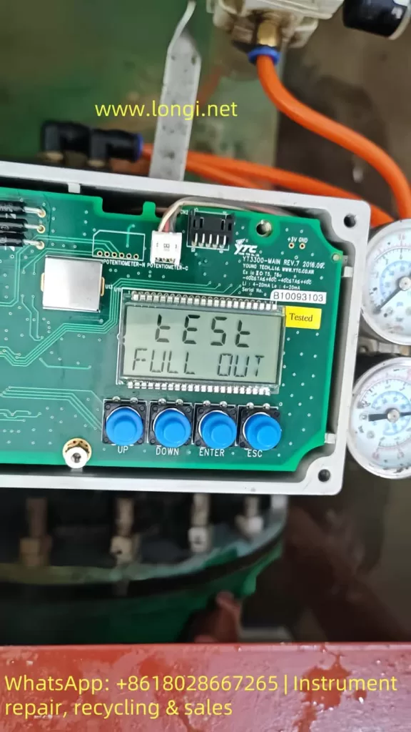
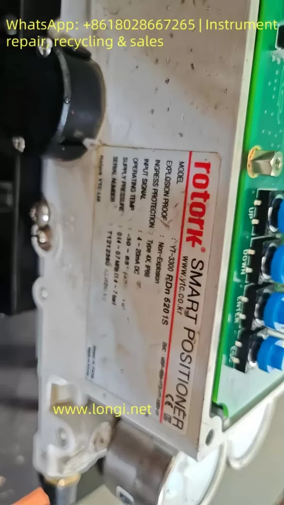
This report addresses the status display of the Rotork YTC YT-3300 RDn 5201S smart valve positioner. The front panel shows the following:
TEST
FULL OUT
7535
The YT-3300 series smart positioner is produced by YTC (Young Tech Co., Ltd.), often labeled under the Rotork brand. It is designed for precise valve actuator control using a 4–20 mA input signal. The unit supports automatic calibration, self-diagnostics, manual testing, and performance optimization.
II. Interpretation of Display Information
1. TEST Mode
The “TEST” message indicates the unit is currently in self-test or calibration mode. This occurs typically during initial power-up, after parameter reset, or when manually triggered.
2. FULL OUT
“FULL OUT” means the actuator has moved to the end of its travel range—either fully open or fully closed—depending on the configured logic.
3. 7535
The number “7535” is not an error code. It usually represents the raw feedback signal from the internal position sensor, such as a potentiometer or encoder, scaled between 0–9999. This value gives the current travel position.
III. Possible Root Causes
The following table summarizes possible causes for this status:
| No. | Possible Cause | Description |
|---|---|---|
| 1 | Power-on self-test | After powering up or parameter loss, the device automatically initiates self-calibration. |
| 2 | Manual test triggered | The test mode may have been manually entered via front-panel buttons. |
| 3 | Feedback sensor issue | A stuck or damaged position sensor can cause the value (7535) to freeze or become invalid. |
| 4 | Air pressure problem | Insufficient or unstable air pressure may prevent the actuator from completing movement. |
| 5 | Mainboard fault | Malfunction of internal controller or microprocessor may lock the unit in test mode. |
IV. Recommended Inspection and Repair Steps
1. Safety and Initial Checks
- Disconnect the actuator from live control and ensure safe access.
- Ensure that air pressure is fully vented to prevent unintended valve motion.
- Confirm the unit is grounded properly (ground resistance <100 ohms).
2. Check Air Supply
- Verify pressure gauges show clean, dry air within 0.14–0.7 MPa (1.4–7 bar).
- Check for blocked air tubing or clogged filters.
3. Exit TEST Mode
- Press the ESC button repeatedly to try returning to the RUN display.
- If that fails, power cycle the unit and enter Auto Calibration mode via the front panel.
4. Execute Auto Calibration
- Set the A/M switch to AUTO.
- Use the keypad to navigate to “AUTO CAL” or “AUTO2 CAL” and execute.
- The actuator will automatically stroke to both ends and calibrate zero and full travel points.
- After successful calibration, the display should return to RUN mode.
5. Verify Position Feedback
If the value “7535” remains static or fails to reflect position changes:
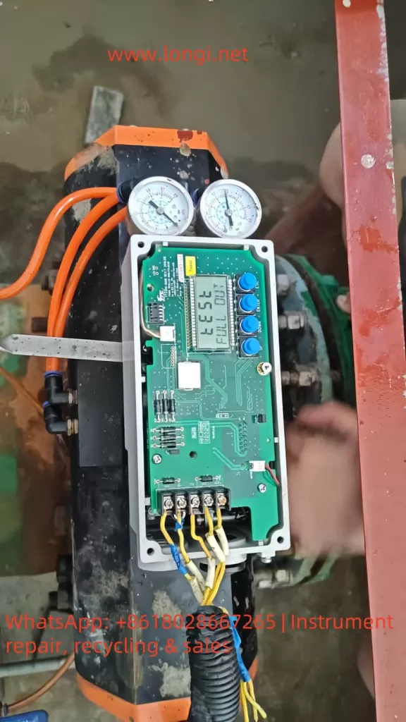
- Open the lower cover and check wiring to the potentiometer (typically yellow, white, blue wires).
- Measure the feedback voltage (should range from ~0.5 to 4.5V DC).
- If no variation is detected with actuator movement, the potentiometer or sensor board may need replacement.
6. Diagnostics and Alarm Monitoring
- Enter the DIAGNOSTIC menu to check for alarm codes or travel deviation alerts.
- If high or low limit alarms (e.g., HH ALRM or LL ALRM) are detected, reset as per standard procedures.
7. Functional Test and Tuning
- After restoring to RUN mode, input varying mA signals and observe feedback value (PV) changes accordingly.
- If actuator motion is slow or unstable, adjust Dead-Zone, Gain, or Filter settings to fine-tune performance.
- Conduct partial stroke tests (PST) if available to verify control reliability.
V. Evaluation and Conclusion
Depending on the inspection and action taken, the following scenarios are possible:
- If Auto Calibration completes successfully and feedback changes smoothly: No hardware failure is present. The unit was simply in test mode after reset.
- If TEST mode persists and feedback value remains frozen: The position feedback sensor or its circuit is likely faulty and needs replacement.
- If actuator fails to move despite calibration attempts: Check for blocked pneumatic valves, damaged tubing, or insufficient pressure.
- If diagnostic menu shows active alarms: Follow alarm-specific reset instructions.
VI. Summary and Recommendations
- Preliminary Conclusion: The current “TEST / FULL OUT 7535” status likely indicates a post-reset auto-test, not a malfunction. However, persistent status or failed calibration points to feedback or hardware problems.
- Recommended Actions:
- First attempt to complete auto calibration;
- Check wiring, feedback sensor, and air supply;
- Monitor diagnostic menu for error indicators;
- Replace faulty components if auto-calibration cannot be completed.
- Follow-up Advice:
- Acquire the official user manual for this specific model;
- Record all air pressures, input/output values, alarms, and parameter settings during troubleshooting for future analysis;
- If manual steps do not resolve the issue, contact the manufacturer or authorized support for further diagnostics or part replacement.