
Introduction
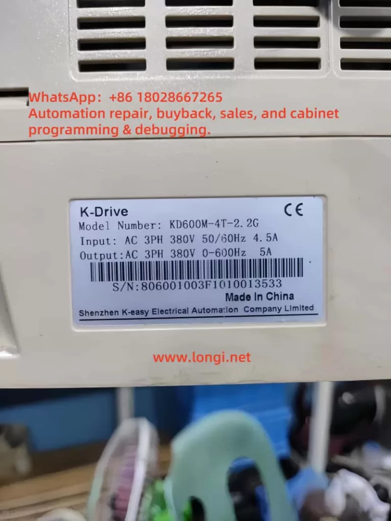
The K-DRIVE KD600M series variable frequency drive (VFD) is a powerful and versatile device designed for motor speed and torque control in various industrial applications. This guide, based on the K-DRIVE KD600M series user manual, provides a detailed overview of the operation panel functions, parameter initialization, password and parameter access restrictions, external terminal forward/reverse control and potentiometer speed adjustment, as well as common fault codes and their resolutions. By mastering these features, users can operate and maintain the VFD efficiently and safely, ensuring optimal performance across different scenarios.
Operation Panel Functions
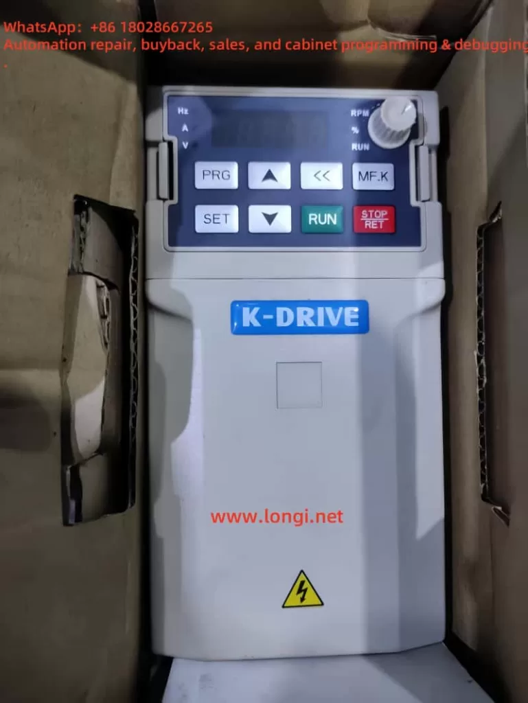
The KD600M series VFD’s operation panel is the central interface for user interaction, integrating intuitive buttons, LED indicators, and a 5-digit display for parameter settings, status monitoring, and motor control. Below are the key functionalities:
Buttons and Controls
The panel includes the following buttons:
- PRG: Enters programming mode to access parameter menus.
- ESC: Exits the current menu or cancels an operation.
- OK: Confirms parameter settings or selections.
- RUN: Starts motor operation.
- STOP: Stops motor operation or resets faults.
- QUICK: Quickly sets commonly used parameters.
- JOG: Enters jog mode for testing or fine-tuning.
- UP/DOWN: Adjusts parameter values or navigates menus.
For example, to adjust the frequency from 0.00Hz to 5.00Hz, users can press PRG to enter the parameter menu, use the UP/DOWN keys to select the target parameter (e.g., P1-04), input the new value, and press OK to confirm.
LED Indicators
The panel’s LED indicators provide real-time status feedback:
- RUN: Green, on indicates running, off indicates stopped, flashing indicates sleep mode.
- L/D/C: Red, off indicates panel control, on indicates terminal control, flashing indicates communication control.
- FWD/REV: Red, off indicates forward, on indicates reverse, flashing indicates direction mismatch.
- TUNE/TC: Red, on indicates torque control, flashing indicates tuning or a fault.
Display Screen
The 5-digit LED display shows frequency, current, voltage, fault codes, and other information. Hexadecimal values are prefixed with “H.” (e.g., P7-29 displays as “H.3f”). The display supports multi-level menu navigation (group → code → value), enabling quick access and modification of parameters.
Related Parameters
Key parameters related to operation panel functions include:
- P7-00 (Jog Run Frequency): Range: 0.00Hz to maximum frequency; Factory default: 6.00Hz.
- P7-01 (Jog Acceleration Time): Range: 0.0s to 3000.0s; Factory default: 10.0s.
- P7-02 (Jog Deceleration Time): Range: 0.0s to 3000.0s; Factory default: 10.0s.
- P7-28 (QUICK/JOG Key Function Selection): Options: 0 (forward jog), 1 (forward/reverse switch), 2 (reverse jog), 3 (panel/remote switch), 4 (panel frequency source switch); Factory default: 0.
- P7-16 (Keyboard Knob Precision): Options: 0 (0.01Hz) to 10 (10Hz); Factory default: 2.
These features make the operation panel a powerful and flexible tool for various control needs.
Parameter Initialization
Parameter initialization is a critical step for restoring default settings or backing up user configurations. The KD600M series offers the following function codes:
P0-28 (Parameter Initialization)
- Options:
- 0: No operation
- 1: Restore factory settings (excludes motor parameters, records, and P0-20)
- 2: Clear records
- 3: Back up user parameters
- 4: Restore backed-up parameters
- Factory Default: 0
- Modifiable State: Running state (★)
To perform initialization, users should enter P0-28 while the device is stopped, set it to 1, and confirm. The VFD will revert to factory settings, preserving motor parameters and run records.
P0-29 (Parameter Upload/Download)
- Options:
- 0: No function
- 1: Upload parameters
- 2: Download parameters (excludes P4 and A1)
- 3: Download parameters (includes P4 and A1)
- 4: Download all parameters
- 5-7: Download modified parameters
- Factory Default: 0
- Modifiable State: Stopped or running state (☆)
This function allows users to back up custom parameters or restore from a backup, suitable for multi-device configurations or fault recovery.
Password and Parameter Access Restrictions
To prevent unauthorized modifications, the KD600M series provides password protection and parameter access restrictions:
Password Protection
- P7-49 (User Password):
- Range: 0 to 65535
- Factory Default: 0
- PF.00 (Factory Password):
- Range: 0 to 65535
- Factory Default: ***** (hidden for security)
Users can enable password protection by setting P7-49. Fault codes like Err25 (EEPROM read/write failure) or Err1A (password entry limit exceeded) may indicate password-related issues, requiring EEPROM chip inspection or technical support.
Parameter Access Restrictions
- B0-00 (Function Code Read-Only Selection):
- 0: Invalid (no restriction)
- 1: Read-only (parameters cannot be modified)
- Factory Default: 0
- Parameter Status:
- ★: Not modifiable during operation (e.g., P0-03: motor control).
- ○: Manufacturer-only modification.
- ●: Read-only (e.g., PF group parameters).
These restrictions ensure the security of critical parameters, preventing accidental changes or unauthorized access.
External Terminal Forward/Reverse Control and Potentiometer Speed Adjustment
The KD600M series supports external terminal control for forward/reverse operation and potentiometer speed adjustment, ideal for automated systems.
Forward/Reverse Control
- Digital Input Terminals (DI1-DI10):
- DI1: Default forward (function code 1).
- DI2: Default reverse (function code 2).
- Supports PNP/NPN modes, switchable via DIP switches.
- Up to 10 digital inputs with optional IO1/IO2 expansion cards.
- P5-11 (Terminal Command Mode):
- 0: Two-wire mode 1
- 1: Two-wire mode 2
- 2: Three-wire mode 1
- 3: Three-wire mode 2
- Factory Default: 0
Wiring Method:
- Connect DI1 and DI2 to a PLC or switch, with the COM terminal as the common return.
- Ensure secure connections to avoid short circuits or poor contact.
Potentiometer Speed Adjustment
- Analog Input Terminals (AI1, AI2):
- Supports 0-10V or 4-20mA input.
- P5-15 (AI1 Minimum Input): Range: 0.00V to 10.00V; Corresponding setting: -100.0% to 100.0%.
- P5-16 (AI1 Maximum Input): Range: 0.00V to 10.00V; Corresponding setting: -100.0% to 100.0%.
- Wiring Method:
- Use a 1-5kΩ potentiometer, connecting to AI1 and +10V-GND terminals (+10V provides up to 10mA power).
- Recommended wiring length is less than 20 meters to minimize signal interference.
Setup Steps:
- Set P5-11 to 0 (two-wire mode 1) to enable terminal control.
- Configure P5-15 and P5-16 to define the potentiometer input range.
- Rotate the potentiometer and observe frequency changes on the display to ensure proper speed adjustment.
Common Fault Codes and Resolutions
The KD600M series manual lists various fault codes with corresponding resolution methods. Below are common faults and their troubleshooting steps:
| Fault Code | Fault Name | Resolution Method |
|---|---|---|
| Err01 | Inverter Module Protection | Check U, V, W terminals for shorts or grounding, inspect overheating, wiring, fans, and vents; contact support if unresolved. |
| Err04 | Acceleration Overcurrent | Check output circuit, motor parameters, acceleration time (P9-22), V/F gain, voltage, load, and VFD capacity; adjust parameters. |
| Err05 | Deceleration Overcurrent | Check output circuit, motor parameters, deceleration time (P9-23), voltage, load, brake unit/resistor, and flux gain; adjust parameters. |
| Err06 | Constant Speed Overcurrent | Check output circuit, motor parameters, voltage, load, and VFD capacity; adjust parameters. |
| Err08 | Acceleration Overvoltage | Check voltage, external force, acceleration time, brake unit/resistor, and motor parameters; adjust settings. |
| Err09 | Deceleration Overvoltage | Check voltage, external force, deceleration time, and brake unit/resistor; adjust settings. |
| Err10 | Constant Speed Overvoltage | Check voltage, external force, and resistor installation; adjust parameters. |
| Err12 | Undervoltage Fault | Check power stability, voltage range, bus voltage, rectifier, and drive/control board; reset or contact support. |
| Err13 | Drive Overload | Reduce load, check motor condition, consider upgrading VFD. |
| Err14 | Motor Overload | Adjust P9-01 settings, check load and motor condition, upgrade VFD if needed. |
| Err15 | Drive Overheating | Lower ambient temperature, clean vents, check fans and thermistor, replace module if necessary. |
| Err17 | Current Detection Fault | Check wiring, current devices, and main/control board; contact support. |
| Err20 | Ground Short Circuit | Check motor and cables for shorts, replace if needed; contact support. |
| Err23 | Input Phase Loss | Check power supply, drive/lightning/main board; contact support. |
| Err24 | Output Phase Loss | Check motor wires, output balance, drive/module; resolve fault or contact support. |
| Err25 | EEPROM Operation Failure | Check EEPROM chip, replace main board if necessary; contact support. |
| Err27 | Communication Fault | Check host, communication settings, and P8 group parameters; adjust wiring/parameters. |
| Err28 | External Fault | Check DI terminal input, reset fault. |
| Err29 | Speed Deviation Excessive | Extend acceleration/deceleration time, reset P9-31/P9-32. |
| Err30/31 | User-Defined Fault 1/2 | Check DI terminal input, reset fault. |
| Err32 | PID Feedback Loss | Check feedback signal, reset PA-13. |
| Err33 | Quick Current Limit | Reduce load, extend acceleration time, or upgrade VFD. |
| Err34 | Load Drop Fault | Reset or adjust P9-28 to P9-30 conditions. |
| Err35 | Input Power Fault | Adjust voltage, extend power cycle. |
| Err37 | Parameter Storage Anomaly | Check DSP-EEPROM communication, replace main board if needed. |
| Err39 | Run Time Reached | Check run time, reset if necessary. |
| Err40 | Cumulative Run Time Reached | Check cumulative run time, reset. |
| Err42 | Motor Switching During Run | Ensure correct motor switching procedure. |
| Err46 | Master-Slave Communication Interrupt | Check master-slave communication connections. |
General Fault Handling Steps
- Power Off Check: Disconnect the VFD power before addressing any fault to ensure safety.
- Refer to Manual: Consult the manual’s troubleshooting section for specific steps based on the fault code.
- Parameter Adjustment: Adjust relevant parameters (e.g., acceleration time P9-22, deceleration time P9-23) according to the fault cause.
- Reset: Use the STOP key or set P9-11 (auto-reset attempts, 0-20, default 0) and P9-13 (reset interval, 0.1s-100.0s, default 1.0s) to reset faults.
- Technical Support: Contact K-DRIVE technical support if the fault persists.
Conclusion
The K-DRIVE KD600M series VFD offers robust control capabilities through its intuitive operation panel, flexible parameter settings, and powerful external control features. By mastering the operation panel functions, parameter initialization, password protection, external terminal control, and fault resolution methods, users can ensure stable operation across various industrial scenarios. It is recommended to always refer to the user manual for detailed guidance and safety precautions to maximize the device’s performance and longevity.