
1. Overview and Error Description
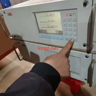
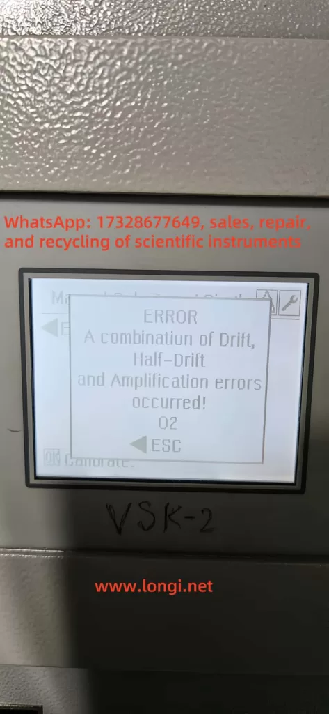
During operation of ABB’s AO2000 series continuous gas analyzers (such as Fidas24, Magnos, etc.), the following error message may be displayed:
ERROR
A combination of Drift,
Half‑Drift and Amplification errors occurred!
02 → ESC
This message indicates that the analyzer has simultaneously detected three types of offset-related faults: Drift, Half-Drift, and Amplification errors. When these faults are combined, the system flags a critical failure (error code 507/02), potentially halting analysis and rejecting calibration until the issue is resolved.
2. Explanation of Each Error
- Drift Error: Occurs when the signal offset exceeds acceptable thresholds, indicating a deviation of the baseline from its expected value.
- Half-Drift: Triggered when the drift exceeds 50% of the allowed range — considered a warning-level error.
- Amplification Error: Involves abnormal gain changes where the signal is either over-amplified or under-amplified, making measurement inaccurate.
A combined error suggests the presence of multiple overlapping issues, usually triggering a safety lock to prevent invalid measurements or faulty gas composition reports.
3. Root Causes of Combined Error
To understand the fault comprehensively, we must examine it from the sensor behavior, calibration process, and environmental conditions:
a) Sensor Aging or Degradation
Infrared, paramagnetic, or thermal conductivity sensors may suffer from aging, leading to unstable offsets and signal gain. Optical sources, sample cells, and pre-amplifiers may degrade over time and trigger drift.
b) Environmental or Sampling Issues
Contaminated sampling lines (moisture, oil mist, or particulate matter) can distort calibration by affecting gas composition. Humidity and temperature fluctuations also contribute to drift and amplification failures.
c) Calibration Gas or Flow Irregularities
Inconsistent span or zero gas flow, or expired gas bottles, can lead to calibration errors. When calibration fails multiple times, the analyzer may flag this combined drift/amplification condition.
4. Fault Classification and Corrective Actions
| Fault Type | Manifestation | Recommended Action |
|---|---|---|
| Drift / Half-Drift | Baseline deviation or slow measurement response | Check drift logs and compare to tolerance |
| Amplification Error | Gain factor changes sharply from historical levels | Evaluate sensor electronics or pre-amp |
| Combined Error 507 | Calibration fails; analyzer halts measurement | Trigger manual calibration and inspect logs |
| Environmental Impact | Errors repeat in humid/contaminated environments | Clean lines, dry filters, verify sample gas |
5. Step-by-Step Troubleshooting Guide
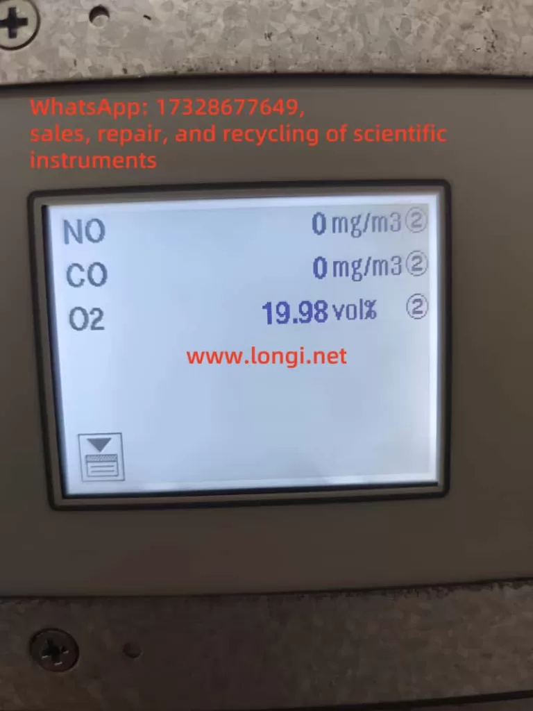
Step 1: View Diagnostic Readings
Access the analyzer menu and retrieve drift, gain, and error logs. Compare with baseline values and specifications.
Step 2: Inspect and Clean Sampling System
- Replace or clean sample tubing, filters, or water traps.
- Verify that the calibration gas is flowing correctly and meets purity specifications.
Step 3: Perform Manual Calibration
Access maintenance mode and carry out a full zero/span calibration. If the system fails again:
- Check whether the instrument is actually drawing calibration gas.
- Monitor flowmeter readings and solenoid valve actuation.
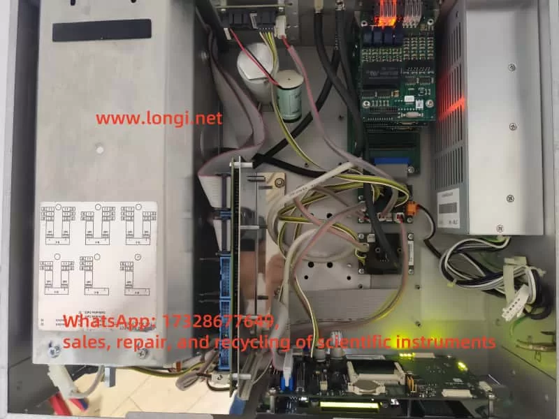
Step 4: Component-Level Inspection
- Replace sensors, detector modules, or signal pre-amplifiers if values are unstable.
- Check power supply stability and internal electronics.
- Reboot analyzer after hardware check.
Step 5: Validate with Monitoring
After repairs, allow the instrument to stabilize and log drift values over 24 hours. Ensure both zero and span values hold within specification.
6. Preventive Maintenance Recommendations
- Daily Drift Monitoring: Log drift rates at least once per shift.
- Monthly or Quarterly Calibration: Use certified calibration gas bottles with verified expiration dates.
- Gas Path Dryness: Keep the system moisture-free using desiccants or active dryers.
- Sensor Lifecycle Tracking: Monitor installation date and replace sensors per manufacturer’s suggested intervals.
- Firmware and Software Updates: Regularly update analyzer software to address known error conditions and optimize calibration routines.
7. Case Study Example
A gas analyzer running for 6+ months triggered a combined 507 error. Drift values reached 180%, amplification deviation was excessive, and span calibration repeatedly failed. After inspection, the calibration gas flow had dropped significantly, and condensation was found in the sampling line.
Corrective action included replacing the filter, drying the line, and restoring gas flow. After performing a fresh zero/span calibration, the analyzer resumed normal operation.
This case confirms that calibration integrity and sample system hygiene are crucial for reliable performance.
8. Conclusion
- Fault nature: This combined error involves overlapping sensor baseline drift, amplification gain deviation, and calibration failure.
- Resolution:
- Review diagnostic metrics.
- Clean sampling path.
- Recalibrate manually.
- Replace modules if needed.
- Reboot and test.
- Establish a preventive maintenance protocol.
- Log and trend drift data periodically.
By maintaining proper calibration procedures, monitoring drift trends, and proactively replacing aging components, operators can avoid 507/02 combined faults and ensure high availability and accuracy from ABB EL3020 or AO2000 gas analyzers.
Note: This article assumes the presence of standard modules such as Uras26, Magnos206, or Fidas24. Detailed troubleshooting should be tailored to your specific analyzer configuration and environmental conditions.