Introduction
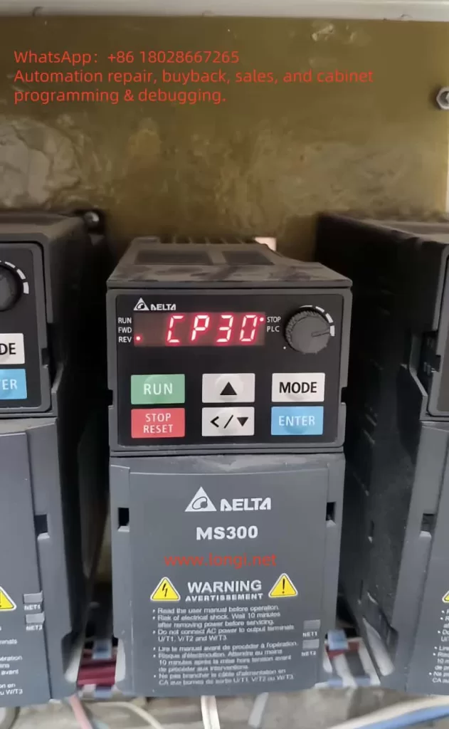
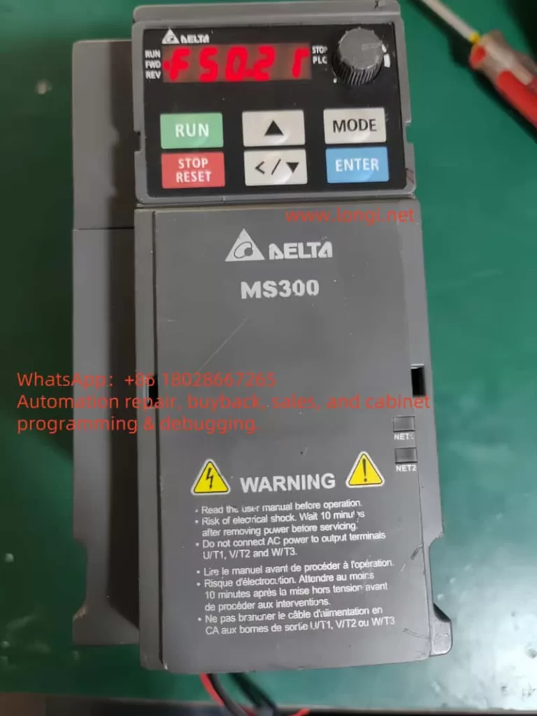
Delta MS300 series inverters are widely used in industrial fields due to their high performance and reliability. However, various faults may occur during use. Among them, CP30 fault (internal communication abnormality) is a relatively common fault. This article will systematically analyze the causes, troubleshooting methods, and solutions of CP30 faults based on official materials and actual cases, helping engineers quickly locate problems and restore equipment operation.

I. Definition and Mechanism of CP30 Fault
1.1 Official Definition
According to Delta’s official technical documents, CP30 is a dedicated error code for internal communication of MS300 series inverters, indicating a communication interruption or signal delay between the control board and the drive board. This fault is usually related to abnormal hardware connections, power fluctuations, or component aging.
1.2 Fault Trigger Scenarios
- Intermittent Fault: The equipment suddenly reports an error after running for a period of time. It temporarily recovers after restarting, but the fault recurs repeatedly.
- After Environmental Changes: Such as restarting after holidays or when there are significant changes in ambient temperature and humidity.
- During Load Fluctuations: Load mutations or frequent starts and stops increase communication pressure.
1.3 Fault Mechanism
The core mechanism of the CP30 fault lies in abnormal data interaction between the control board and the drive board, which may be caused by the following reasons:
- Hardware Connection Issues:
- Loose or oxidized wiring at the control terminal block.
- Communication cables longer than 15 meters without signal repeaters.
- Power lines and control lines not laid in separate layers, causing electromagnetic interference.
- Power Fluctuations:
- The 5V/12V output voltage of the switching power supply fluctuates beyond ±5%, leading to unstable power supply for the control board.
- Harmonic interference or voltage mutations in the input power.
- Component Aging:
- RS485 communication chip failure on the main control board.
- EEPROM memory damage or degradation of optocoupler devices (such as PC923, PC929).
- Software and Parameters:
- Incompatible firmware versions or incorrect parameter configurations.
- Communication protocol settings not matching the upper computer.

II. Troubleshooting Process for CP30 Fault
2.1 Preliminary Inspection
2.1.1 Appearance and Wiring Inspection
- Control Terminal Block:
- Check if the wiring is loose or oxidized, focusing on communication terminals (such as RS485 interfaces).
- Ensure that the shielding layer of the cable is grounded at one end to avoid grounding loop interference.
- Communication Cables:
- Measure the cable length. If it exceeds 15 meters, install a signal repeater.
- Check if the cable insulation layer is damaged to avoid short circuits or crosstalk.
- Layered Wiring:
- Ensure that power lines (main circuits) and control lines (signal lines) are laid separately with a spacing of at least 30cm.
2.1.2 Power and Grounding Inspection
- Switching Power Supply Test:
- Use a multimeter to measure the control board power supply voltage (5V/12V). The fluctuation should be ≤±5%.
- If the voltage is abnormal, check if the filter capacitor is aging or replace the switching power supply module.
- Grounding Verification:
- Confirm that the grounding terminal is reliably connected and the grounding resistance is ≤4Ω.
- Avoid sharing ground wires with power lines to prevent ground wire interference.
2.2 In-depth Hardware Detection
2.2.1 Circuit Board Inspection
- Connector Status:
- Disassemble the inverter and observe if the connectors between the main control board and the drive board are offset, broken, or oxidized.
- Clean the connectors and re-plug them to ensure good contact.
- Capacitor and Optocoupler Detection:
- Measure the capacitance value of the main circuit filter capacitor. If it is below 80% of the rated value, replace it.
- Use an oscilloscope to detect the input and output waveforms of optocoupler devices (such as PC923, PC929) to confirm there is no distortion or delay.
2.2.2 Communication Chip Test
- RS485 Chip Detection:
- Use a multimeter to measure the voltage difference between the A and B lines of the RS485 chip. The normal value should be 2-3V.
- If the voltage is abnormal, replace the RS485 communication chip or the control board.
- EEPROM Verification:
- Test the EEPROM by initializing the inverter parameters (retain motor nameplate data).
- If the fault persists after initialization, replace the control board.
2.3 Software and Parameter Inspection
- Parameter Initialization:
- Restore the inverter to factory settings and re-enter motor parameters (such as power, number of poles, rated current, etc.).
- Confirm that parameters 06-17~06-22 (communication-related parameters) are set correctly.
- Firmware Version Check:
- Contact Delta or check the firmware version through the inverter panel.
- If the version is too old, upgrade to the latest version to fix potential communication vulnerabilities.
- Communication Protocol Verification:
- Confirm that the communication protocol (such as Modbus, CANopen) of the upper computer (such as PLC, touch screen) matches the inverter settings.
- Use a serial debugging tool to simulate communication and verify if data interaction is normal.
III. Solutions for CP30 Fault
3.1 Hardware Repair
- Wiring Optimization:
- Replace oxidized or loose wiring terminals and use tinned copper wires with crimped terminals.
- Install signal repeaters or use shielded twisted pairs to improve communication stability.
- Component Replacement:
- Replace aging capacitors, optocouplers, or RS485 chips.
- If the control board is damaged, contact Delta for original replacement boards.
- Power Supply Improvement:
- Install three-phase reactors or harmonic filters to suppress input power harmonics.
- Replace with high-precision switching power supply modules to ensure stable power supply.
3.2 Software Adjustment
- Parameter Optimization:
- Adjust the communication timeout time (parameters 14-70~14-73) and extend it appropriately to adapt to complex environments.
- Disable unnecessary communication functions to reduce data interaction.
- Firmware Upgrade:
- Download the latest firmware from Delta’s official website and upgrade the control board with a dedicated programmer.
- Protocol Adaptation:
- Modify the upper computer program to ensure that the communication instruction format is compatible with the inverter.
- Use intermediate devices (such as gateways) to convert different communication protocols.
3.3 Preventive Measures
- Regular Maintenance:
- Check the tightness of wiring terminals quarterly and clean dust on circuit boards.
- Test capacitor values and optocoupler performance annually, and replace aging components in advance.
- Environmental Optimization:
- Ensure that the inverter is installed in a well-ventilated environment to avoid high temperature, high humidity, or dust pollution.
- Keep away from high-power equipment or electromagnetic interference sources, and install shielding covers if necessary.
- Backup and Monitoring:
- Regularly back up inverter parameters for quick recovery in case of faults.
- Install communication status monitoring modules for real-time abnormality alerts.
IV. Typical Case Analysis
Case 1: Intermittent CP30 Fault
Phenomenon: An MS300 inverter in a factory frequently reported CP30 after holidays. It temporarily operated normally after restarting but failed again after a few hours.
Troubleshooting Process:
- Checked the control terminal block and found severe oxidation of the wiring, increasing contact resistance.
- Measured the communication cable length as 20 meters without a repeater, causing significant signal attenuation.
- Disassembled the inverter and found oxidation on the pins of the RS485 chip on the main control board, with distorted communication waveforms.
Solution: - Cleaned and tightened the wiring terminals and replaced oxidized cables.
- Installed a signal repeater to shorten the effective communication distance.
- Replaced the RS485 chip to restore communication stability.
Result: The fault was completely eliminated, and the equipment operated normally for 3 months.
Case 2: CP30 Fault Caused by Parameter Configuration
Phenomenon: A newly installed MS300 inverter frequently reported CP30 during commissioning, but no hardware abnormalities were found.
Troubleshooting Process:
- Found that the engineer mistakenly set the communication timeout time to an extremely short value, causing data interaction interruption.
- The firmware version was too old, with communication protocol compatibility issues.
Solution: - Adjusted the communication timeout time to the default value and optimized other communication parameters.
- Upgraded the firmware to the latest version to fix protocol vulnerabilities.
Result: The fault was immediately eliminated, and the equipment was successfully put into operation.
V. Conclusion
The CP30 fault is a relatively complex internal communication abnormality in Delta MS300 inverters, requiring systematic troubleshooting from multiple dimensions such as hardware connections, power quality, component aging, and software configurations. By standardizing wiring, conducting regular maintenance, optimizing parameters, and replacing components, such faults can be effectively solved. Engineers should combine official materials with actual cases, flexibly use detection tools, and gradually narrow down the fault scope to achieve rapid repair.
