
Introduction
In industrial automation, variable frequency drives (VFDs) play a central role in motor control and energy savings. Among them, the Schneider Electric ATV312 series has gained wide application in medium and small-power motor systems due to its reliability and flexible parameter configuration. However, during long-term operation, users often encounter the ObF fault.
This article provides a systematic explanation of the causes, detection methods, and corrective measures for the ObF fault. It also refers to details in the official ATV312 Programming Manual, giving readers a clear, logical, and practical guide.
I. Definition of the ObF Fault
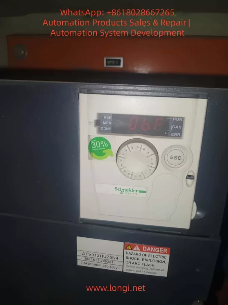
On the ATV312 display, ObF stands for Overvoltage Fault.
This means: when the DC bus voltage exceeds its permissible threshold, the drive shuts down and generates a fault alarm to protect internal circuits.
Symptoms include:
- Drive display shows “ObF”
- Motor stops abruptly
- Fault relay outputs a signal
The root cause is the excessive regenerative energy fed back into the DC bus during motor deceleration or braking, which raises capacitor voltage beyond the safe range.
II. Typical Scenarios Leading to ObF
- Rapid Deceleration
- The motor’s inertia releases kinetic energy into the DC bus.
- Common with fans, centrifugal machines, and hoists.
- Excessive Supply Voltage
- Input supply exceeds the rated range (380–600 V).
- Often occurs in weak or fluctuating grids.
- Missing or Faulty Braking Resistor
- Without a braking resistor or with a damaged unit, the excess energy cannot dissipate.
- Unreasonable Parameter Settings
- Too short deceleration time (dEC).
- Frequent starts and stops causing energy surges.
- Mechanical Anomalies
- Transmission system back-driving the motor or abnormal loads.
III. Consequences of ObF
- Unexpected Downtime – Production line interruption and economic losses.
- Electrical Stress – Repeated high bus voltage damages IGBTs and capacitors.
- Component Aging – Frequent resets accelerate wear of electronic components.
Thus, preventing ObF is essential for maintaining stable operation.
IV. Diagnostic Process
- Check Input Voltage
- Ensure voltage is within rated range using a multimeter or power analyzer.
- Verify Application Type
- Identify whether the load is high inertia.
- Inspect Braking Circuit
- Confirm resistor installation, capacity, and braking unit health.
- Check Parameters
- Focus on deceleration time (dEC), braking settings (brA), and motor parameters.
- Test Run
- Increase dEC and monitor whether the fault reoccurs.
- If still present, braking resistor or additional hardware is required.
V. Manual-Based Optimization
According to the ATV312 Programming Manual:
- Deceleration Time (dEC)
- Factory setting: ~3–5s.
- Recommendation: increase to 10–20s for high-inertia loads.
- Braking Parameter (brA)
- When using a braking resistor, disable slope adaptation (brA=No) to ensure resistor engagement.
- Bus Circuit Notes
- The PO–PA/+ terminals must remain connected; otherwise, drive circuits may be damaged.
VI. Corrective Actions
1. Software Adjustments (Lowest Cost)
- Increase deceleration time (dEC).
- Avoid frequent start/stop and emergency stop operations.
- Optimize control logic to reduce unnecessary reversals.
2. Hardware Enhancements
- Install a braking resistor sized for the drive’s rated power.
- Upgrade the resistor if already installed but overheating.
- Add an AC line reactor to reduce voltage spikes in weak grid supply.
3. System-Level Solutions
- Use regenerative drives or braking chopper modules.
- Select a drive model tailored for fan or hoist applications.
VII. Case Studies
Case 1: Fan Application
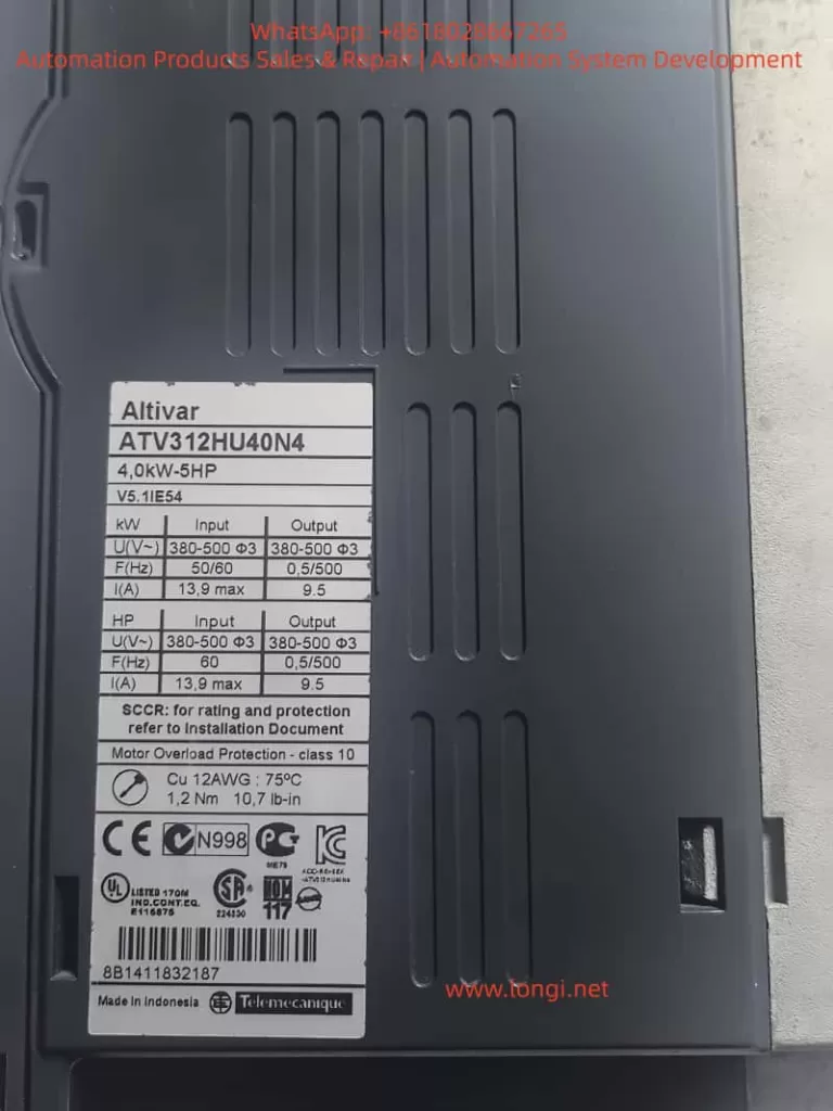
- Drive: ATV312HU75N4 in a cement plant.
- Problem: Frequent ObF faults during deceleration.
- Findings: dEC set to 5s; no braking resistor installed.
- Solution: Extended dEC to 15s, installed 100Ω/2kW resistor.
- Result: Fault eliminated, system stabilized.
Case 2: Hoist Application
- Drive: ATV312 controlling a mining hoist.
- Problem: ObF occurs during heavy-load descent.
- Findings: Input voltage normal at 410V; resistor installed but overheated.
- Solution: Replaced with higher capacity 75Ω/5kW resistor and added forced air cooling.
- Result: Continuous stable operation.
VIII. Preventive Maintenance
- Routine Checks
- Inspect resistor for overheating or discoloration.
- Measure resistance to verify specification.
- Parameter Backup
- Use Schneider SoMove software to store settings.
- Real-Time Monitoring
- Add bus voltage monitoring in SCADA systems.
- Trigger alarms before faults occur.
- Environmental Conditions
- Ensure adequate cooling and dust removal to prevent derating.
IX. Conclusion
The ObF fault is one of the most common alarms in Schneider ATV312 drives, directly linked to DC bus overvoltage.
Key insights:
- Software tuning (increase dEC) is the first corrective measure.
- Hardware configuration (braking resistor, reactors) is essential for high-inertia applications.
- System-level planning ensures the drive is suited to the operating environment.
By combining parameter optimization, proper hardware sizing, and proactive maintenance, ObF faults can be effectively eliminated, ensuring long-term reliable operation of ATV312 drives.