Understanding “X-ray Tube Failure” — Engineering-Level Diagnosis and Repair Decision Guide
Introduction
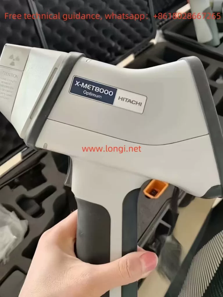
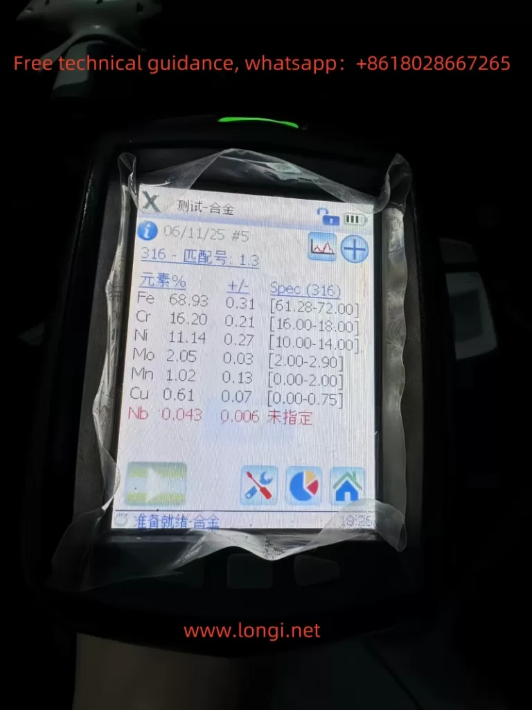
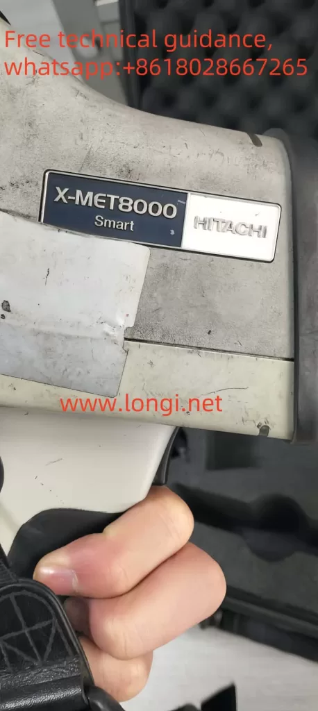
The Hitachi X-MET 8000 handheld XRF analyzer is widely used in alloy identification, PMI inspection, scrap sorting, and on-site material analysis. In daily service practice, a common failure scenario is frequently reported:
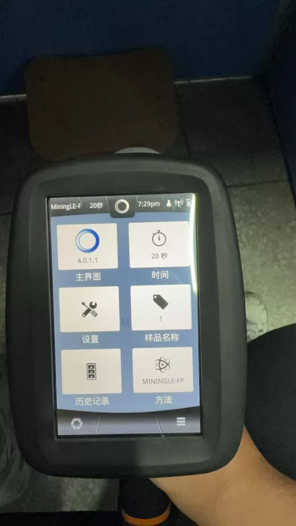
- The instrument powers on normally
- The touchscreen interface works correctly
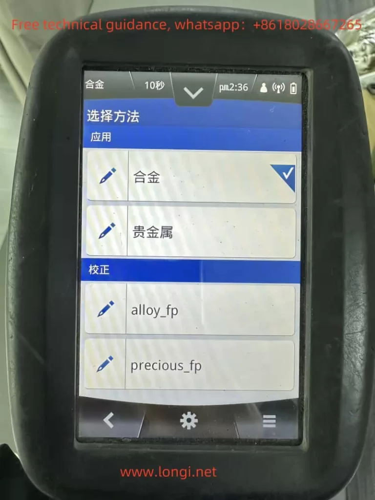
- Measurement methods and settings are accessible
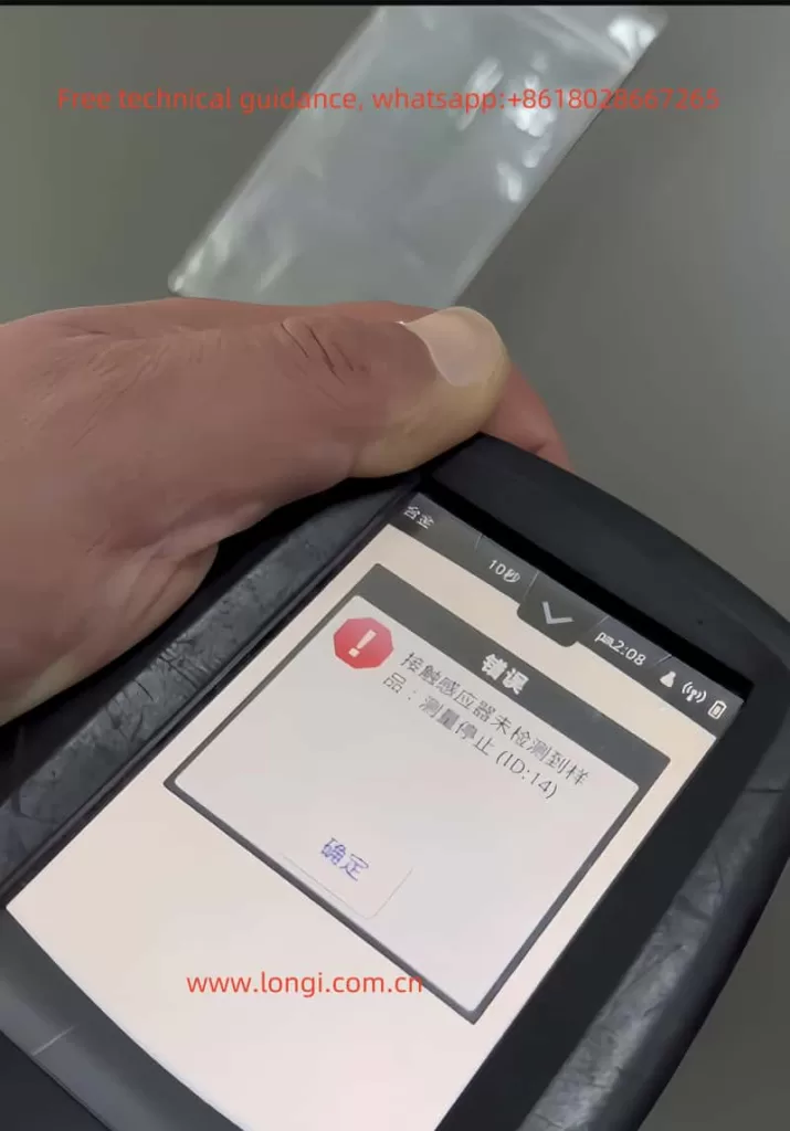
- Measurement starts but immediately fails
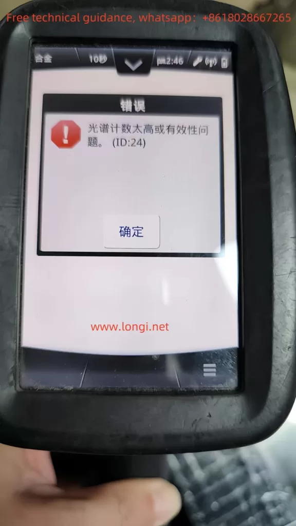
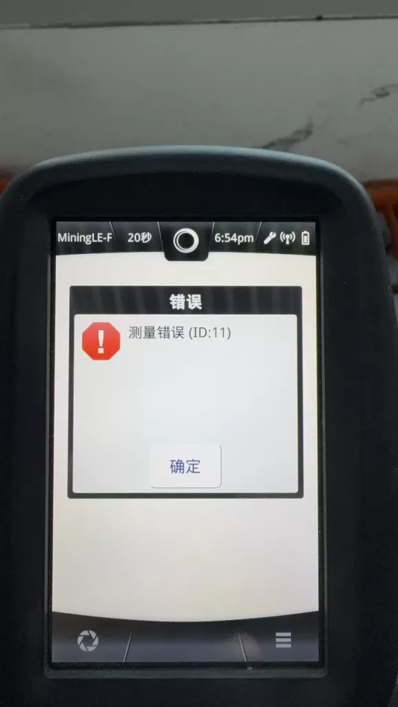
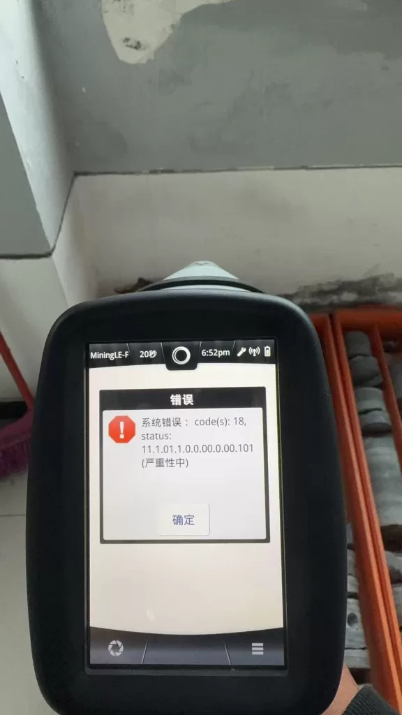
- The system displays error messages such as:
- “System Error: code(s): 18”
- “Measurement Error (ID:11)”
When reported to official service channels, users often receive a brief response:
“The X-ray tube is defective and must be replaced.”
While this conclusion may be acceptable from a manufacturer’s service policy perspective, it is technically incomplete.
This article explains what “X-ray tube failure” actually means, how these errors are triggered internally, and how engineers can determine whether the instrument is truly beyond repair.
What Does “X-ray Tube” Mean in the X-MET 8000?
In XRF systems, the term “X-ray tube” does not refer to a lamp or light source. It is a high-voltage vacuum device responsible for generating primary X-rays.
In the Hitachi X-MET 8000, the X-ray tube:
- Operates at tens of kilovolts (typically 40–50 kV)
- Emits X-rays that excite atoms in the sample
- Enables fluorescence detection by the SDD detector
Without a functioning X-ray tube system, elemental analysis is physically impossible, regardless of software or detector condition.
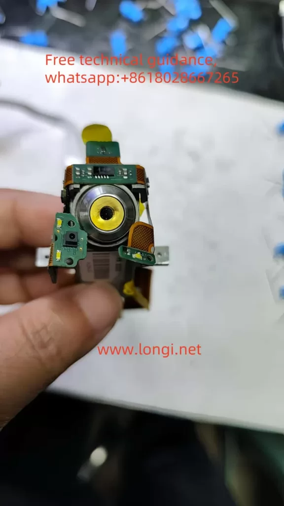
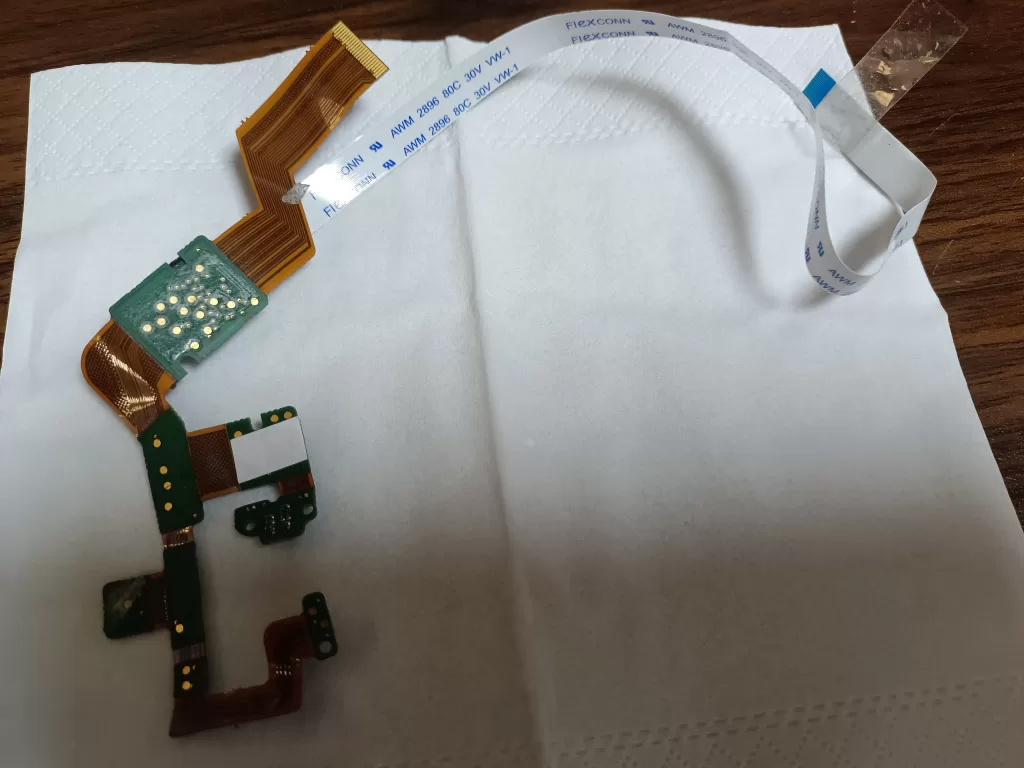
X-ray Generation System Architecture
From an engineering standpoint, the X-ray generation chain in the X-MET 8000 consists of multiple subsystems:
Main CPU / Operating System
↓
X-ray Control Logic
↓
High Voltage Generator (HV Module)
↓
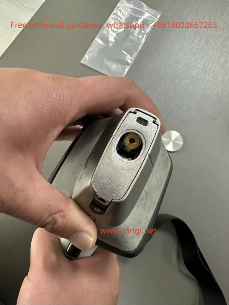
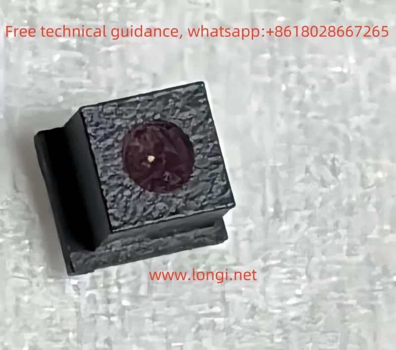
X-ray Tube
↓
Collimator and Window
Failure at any point in this chain will present itself to the user as a measurement error.
This is a key reason why many different faults are generalized by manufacturers as “X-ray tube failure.”
Interpreting System Error Code(s): 18
The “System Error: code(s): 18” message is not a random software bug.
In Hitachi / Olympus / Evident XRF platforms, system errors are bitwise status evaluations of hardware readiness.
Error code 18 typically indicates:
- X-ray generation system failed to reach operational state
- High-voltage enable confirmation missing
- Tube current feedback abnormal or absent
- Safety interlock preventing X-ray emission
Importantly, this error does not specify which component failed—only that the X-ray system did not pass internal checks.
Understanding Measurement Error (ID:11)
Measurement Error (ID:11) is a result-level error, not a root-cause error.
It means:
During measurement, the system did not detect a valid X-ray fluorescence signal.
This condition may be caused by:
- No X-ray emission
- Insufficient tube current
- High-voltage shutdown
- Safety interlock interruption
It does not automatically prove that the X-ray tube itself is defective.
Why Official Service Diagnoses “X-ray Tube Failure”
Manufacturers use a module replacement service model:
- No component-level troubleshooting
- No HV board repair
- No interlock diagnostics beyond basic checks
From this standpoint:
- Any X-ray system malfunction → replace X-ray assembly
- X-ray assembly includes tube + HV + shielding
- Result: “X-ray tube failure”
This approach simplifies liability, radiation safety compliance, and service logistics—but sacrifices diagnostic precision.
Real-World Failure Probability Distribution
Based on field repair experience, actual root causes are distributed as follows:
| Failure Area | Likelihood | Notes |
|---|---|---|
| X-ray tube aging | High | Consumable component |
| HV generator failure | High | MOSFETs, drivers, protection |
| Tube current sensing fault | Medium | Feedback circuit |
| Safety interlock open | Medium | Probe or housing switches |
| Cable or connector issue | Low | Shock or liquid ingress |
A significant portion of units diagnosed as “tube failure” are actually repairable HV or interlock issues.
Practical Engineering Diagnostics (Without Factory Tools)
Acoustic High-Voltage Test
When measurement starts, listen carefully:
- Audible high-voltage “hiss” → HV likely enabled
- No sound at all → HV not starting or blocked
This simple test immediately separates control-side failures from tube-side failures.
Low-Voltage Input Stability Check
Using a multimeter:
- Verify stable DC input to the HV module
- Observe voltage behavior during measurement start
If voltage collapses immediately, the problem is likely within the HV power stage—not the tube itself.
HV Enable Signal Verification
Most HV modules include an enable control line:
- Idle state: 0 V
- Measurement state: logic high (3.3 V or 5 V)
If no enable signal is present, investigate:
- Safety interlocks
- Control board logic
- Firmware permission state
When Can the X-ray Tube Be Considered Truly Defective?
A tube should only be considered irreversibly defective when:
- High voltage is confirmed to start
- Tube current remains zero or unstable
- No X-ray output is detected
- Power, control, and safety systems are verified normal
Only under these conditions does replacing the tube make technical sense.
Repair vs Replacement Decision Logic
From a cost and engineering perspective:
- Official tube replacement often equals the value of a used X-MET unit
- Component-level repair can restore full functionality at a fraction of the cost
- Partial repair enables resale as refurbishable equipment
A rational decision process includes:
- Confirm root cause
- Attempt HV or interlock repair first
- Evaluate tube replacement only if proven necessary
- Consider secondary market strategies if uneconomical
Conclusion
“X-ray tube failure” is not a precise technical diagnosis—it is a service-level classification.
True engineering evaluation requires separating:
- Control logic failures
- High-voltage generation issues
- Safety interlock interruptions
- Genuine tube end-of-life conditions
By understanding the internal architecture and error logic of the Hitachi X-MET 8000, technicians and equipment owners can avoid unnecessary replacement, reduce costs, and make informed repair or resale decisions.