I. Instrument Overview and Basic Operations
1.1 Instrument Introduction
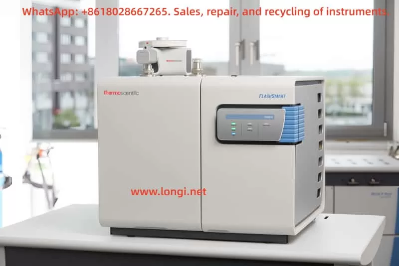
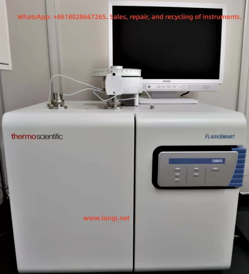
The Thermo Fisher FlashSmart Elemental Analyzer is a fully automated organic elemental analysis system that employs the dynamic combustion method (modified Dumas method) to determine nitrogen, carbon, hydrogen, and sulfur content. It measures oxygen content through high-temperature pyrolysis. This instrument can be configured with a single-channel or dual independent-channel system, and the MultiValve Control (MVC) module enables automatic dual-channel switching for analysis.
Main Technical Parameters:
- Detector Type: Thermal Conductivity Detector (TCD)
- Power Supply: 230V ± 10%, 50/60Hz, 1400VA
- Dimensions: 50cm (height) × 59cm (width) × 58cm (depth)
- Weight: 65kg
- Maximum Operating Temperature: 1100℃
- Gas Requirements: High-purity helium (carrier gas), oxygen (combustion aid), argon (for specific configurations)
1.2 Safety Precautions
Hazardous Operation Warnings:
- High Voltage Risk: The instrument contains high-voltage components. Non-professionals are prohibited from opening the electrical compartment.
- High-Temperature Surfaces: The furnace can reach temperatures up to 1100℃. Avoid contact during operation.
- Gas Safety: Hydrogen use requires extreme caution, as concentrations as low as 4% pose an explosion risk.
- Chemical Hazards: Wear protective gear when handling reaction tube packing materials and sample ashes.
Personal Protective Equipment (PPE) Requirements:
- Eye Protection: Splash-resistant goggles
- Hand Protection: White nitrile gloves (for chemicals)/heat-resistant gloves (for high-temperature operations)
- Respiratory Protection: Dust masks
- Body Protection: Lab coats + plastic aprons
1.3 Startup Preparation Procedure
Gas Connection:
- Helium Inlet Pressure: 2.5bar (36psig)
- Oxygen Inlet Pressure: 2.5-3bar (36-44psig)
- Argon Inlet Pressure: 2.5bar (N/Protein configuration) or 4-4.5bar (NC Soils configuration)
- Leak Testing: Perform on all gas lines.
Power Connection:
- Confirm voltage stability at 230V ± 10%.
- Ensure proper grounding; avoid sharing circuits with large motor equipment.
Software Installation:
- System Requirements: Windows 7/8/10, at least 1GB hard drive space.
- Install EagerSmart data processing software and drivers.
II. Calibration and Adjustment Procedures
2.1 Initial Setup
Hardware Configuration Steps:
- Select Reaction Tube Configuration Based on Analysis Needs:
- CHN Mode: Quartz reaction tube + chromium oxide/reduced copper/cobalt oxide packing.
- CHNS Mode: Quartz reaction tube + copper oxide/electrolytic copper packing.
- O Mode: Quartz reaction tube + nickel-plated carbon/quartz shavings packing.
- N Mode: Dual reaction tubes in series + Plexiglas adsorption filter.
- Install Autosampler:
- MAS Plus Solid Autosampler: Up to 125-position sample tray.
- AI 1310/AS 1310 Liquid Autosamplers: 8-position or 105-position sample trays.
- Connect MVC Module (Dual-Channel Configuration):
- Remove bypass panel from the rear.
- Connect gas lines for left and right channels.
- Configure dual MAS Plus autosamplers.
2.2 System Calibration
Three-Step Calibration Method:
- Leak Testing:
- Initiate automatic leak detection via software.
- Acceptable Leak Rate: <0.1mL/min.
- Use soapy water to locate leaks if detected.
- Signal Baseline Adjustment:
- Set TCD detector temperature constant (typically 40-120℃).
- Adjust bridge voltage to 5V.
- Baseline Drift: Should be <0.1mV/10min.
- Standard Curve Establishment:
- Use high-purity standards like acetanilide (nitrogen 16.09%, carbon 71.09%, hydrogen 6.70%).
- Minimum Concentration Gradients: 5 points (recommended range: 0.1-5mg).
- Correlation Coefficient (R²): Should be >0.999.
Calibration Frequency Recommendations:
- Daily Use: Calibrate after each startup.
- Continuous Analysis: Verify calibration every 50 samples.
- After Consumable Replacement: Recalibration is mandatory.
2.3 Method Optimization
Parameter Adjustment Guidelines:
- Oxygen Injection Time:
- Regular Samples: 4-6 seconds.
- Refractory Samples: Extend to 8 seconds.
- High-Sulfur Samples: Add vanadium pentoxide as a combustion aid.
- Furnace Temperature Settings:
- Combustion Furnace: 950-1100℃.
- Reduction Furnace: 840℃.
- Pyrolysis Furnace (O Mode): 1060℃.
- Carrier Gas Flow Rate:
- Helium: 100-140mL/min.
- Reference Gas: 30-50mL/min.
III. Routine Maintenance
3.1 Regular Maintenance Schedule
Maintenance Schedule Table:
| Maintenance Item | Frequency | Key Operation Points |
|---|---|---|
| Reaction Tube Regeneration | Every 200 analyses | Empty packing material, incinerate at 550℃ for 2 hours. |
| Adsorbent Replacement | Monthly | Activate molecular sieve at 300℃, replace desiccant (silica gel) promptly. |
| Autosampler Cleaning | Weekly | Ultrasonically clean tin/silver cups, inspect piston seals. |
| Chromatographic Column Aging | Quarterly | Age at 280℃ with carrier gas for 8 hours. |
| Comprehensive System Verification | Annually | Conducted by a professional engineer. |
3.2 Key Component Maintenance
Reaction Tube Packing Guidelines:
- Quartz Reaction Tubes:
- Begin packing from the conical end.
- Compact each layer with a dedicated tamping rod.
- Separate layers with quartz wool.
- Maintain total packing height at 80% of tube length.
- HPAR Alloy Steel Reaction Tubes:
- Must be used with crucibles.
- Ensure uniform distribution of oxidation catalysts.
- Use dedicated tools for installation/removal.
Adsorption Filter Maintenance:
- Large (Plexiglas) Filters:
- Packing sequence: Quartz wool → soda lime → molecular sieve → silica gel.
- Pre-moisten soda lime with 0.5mL water.
- Small (Pyrex) Filters:
- Used in CHNS/O modes.
- Packing: Quartz wool → anhydrous magnesium perchlorate.
3.3 Consumable Replacement Intervals
Recommended Replacement Intervals:
- Quartz Wool: Replace when changing reaction tube packing.
- Reduced Copper: Every 500 analyses.
- Oxidation Catalyst: Every 300 analyses.
- Nickel-Plated Carbon (O Mode): Every 150 analyses.
- TCD Filament: Replace when baseline noise occurs.
- Sealing O-Rings: Replace if leaks are detected or every 6 months.
IV. Troubleshooting and Solutions
4.1 Common Error Codes
Error Code Table:
| Code | Meaning | Solution |
|---|---|---|
| E01 | Left Furnace Temperature Exceeded | Check thermocouple connection, restart system. |
| E04 | TCD Signal Overflow | Adjust gain, verify carrier gas purity. |
| E12 | Safety Cutoff Triggered | Check cooling fan, allow system to cool. |
| E25 | EFC-t Module Flow Abnormality | Check for gas line blockages, clean filter. |
| E33 | Autosampler Communication Failure | Reconnect cables, verify port settings. |
4.2 Typical Problem Resolution
Analysis Result Anomaly Investigation:
- Low Nitrogen Results:
- Check if reduced copper is失效 (discolored black).
- Verify adequate oxygen injection.
- Confirm complete sample combustion (observe flame).
- Sulfur Peak Tailings:
- Replace copper oxide packing layer.
- Add vanadium pentoxide combustion aid.
- Check chromatographic column connections for leaks.
- Unstable Oxygen Results:
- Verify nickel-plated carbon packing height (should be 60mm).
- Confirm silver cup seal integrity.
- Validate pyrolysis furnace temperature stability (±2℃).
Hardware Fault Handling:
- Furnace Temperature Failure to Rise:
- Check SSR solid-state relay status.
- Measure transformer output voltage (should be 48V AC).
- Confirm fuse integrity (AC 1112 board F1/F2).
- Abnormal Gas Flow:
- Clean EFC-t module filter.
- Verify solenoid valve EV1-EV4 operation.
- Calibrate flow sensors S1/S2.
- TCD Baseline Drift:
- Extend equilibration time to 2 hours.
- Verify reference gas flow stability.
- Replace aged filament.
4.3 Emergency Response Procedures
Safety Emergency Plan:
- Gas Leak:
- Immediately close cylinder main valve.
- Activate laboratory ventilation system.
- Avoid operating electrical equipment.
- Furnace Overheating:
- Trigger front panel emergency stop button.
- Cut off main power supply.
- Purge system with inert gas.
- Abnormal Combustion:
- Maintain system enclosure.
- Direct exhaust through fume hood.
- Do not cool directly with water.
V. Advanced Application Techniques
5.1 Special Sample Handling
Solutions for Challenging Samples:
- High Inorganic Salt Samples:
- Use quartz crucibles to prevent corrosion.
- Reduce quartz wool between packing layers.
- Increase oxygen injection pressure by 10%.
- Volatile Liquids:
- Utilize AI 1310 liquid autosampler.
- Adsorb sample onto diatomaceous earth.
- Preheat injection needle to 40℃.
- Viscous Samples:
- Grind with quartz sand for homogenization.
- Use specially shaped tin cups.
- Extend combustion time by 20%.
5.2 Data Quality Enhancement
Best Practice Recommendations:
- Sample Preparation:
- Homogenize to below 80 mesh.
- Pre-dry samples with >5% moisture content.
- Avoid fluorine-containing containers.
- Weighing Techniques:
- Use blank tin cups for calibration with microsamples (<1mg).
- Employ “sandwich” loading method for highly volatile samples.
- Utilize a 0.1μg precision balance.
- Quality Control:
- Insert standard samples every 10 analyses.
- Maintain parallel sample deviation <1.5%.
- Retain all original chromatograms.
5.3 Automation Features
Intelligent Function Applications:
- Standby Mode:
- Reduce carrier gas to 10mL/min.
- Maintain furnace temperature at 50% of setpoint.
- Auto-wake via timer function.
- Sequence Analysis:
- Supports 125-sample unattended operation.
- Enables alternating method runs.
- Auto-generates comprehensive reports.
- Remote Monitoring:
- View system status remotely via EagerSmart software.
- Set up email alerts.
- Auto-backup data to network.
VI. Appendices and Support
6.1 Technical Specifications Summary
Key Parameter Quick Reference Table:
- Detection Limits: N/C/H 0.01%, S/O 0.02%
- Precision: RSD <0.5% (for conventional elements)
- Analysis Time: CHN 5min, O 4min, CHNS 6min
- Sample Size: 0.01-100mg (solid), 0.1-10μL (liquid)
- Gas Consumption: Approximately 10L helium per sample
6.2 Regulatory Compliance
Certifications and Compliance:
- CE Certification: Complies with EN 61010-1 safety standards.
- RoHS: Complies with Directive 2011/65/EU.
- WEEE: Classification number 23103000.
- GLP/GMP Compliance: Meets regulatory requirements.
This guide is based on the FlashSmart Elemental Analyzer Operating Manual (P/N 31707001, Revision E) and covers key points for the instrument’s operational lifecycle. Always adapt usage to specific configurations and application needs while strictly adhering to local safety regulations.