Posted on

Siemens G120C Inverter F30004 Fault: Analysis and Troubleshooting Strategies


1. Fault Definition and Background

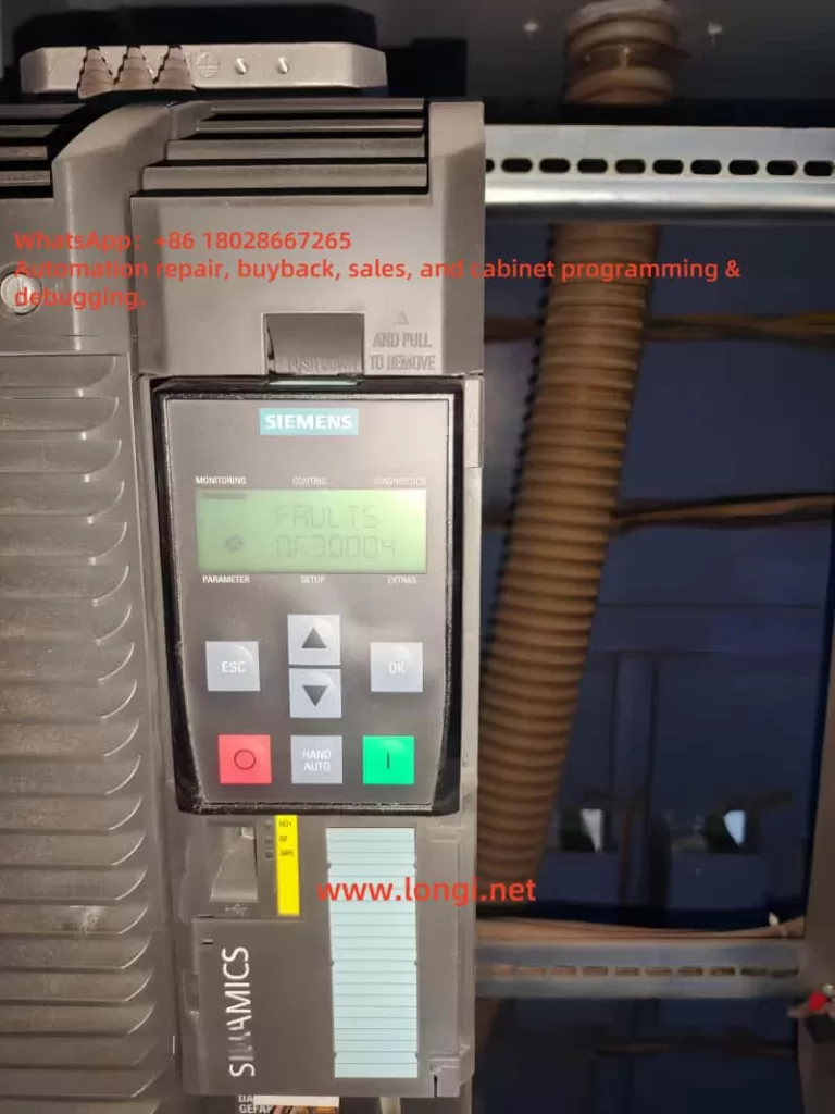
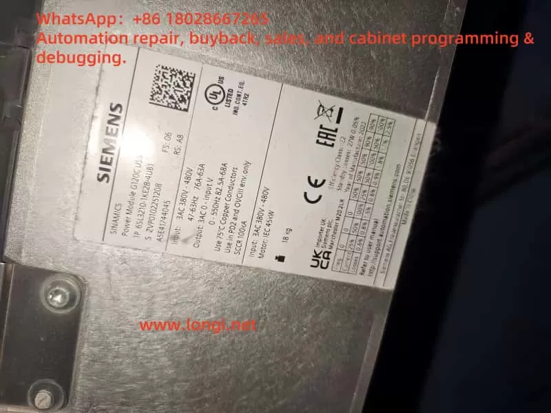
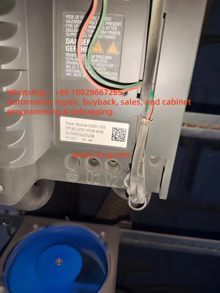
The “F30004” fault is a common error code in the SINAMICS G120C series of Siemens inverters. It indicates:

  • Power unit: Overtemperature heatsink AC inverter

In other words, the temperature of the power module’s heatsink has exceeded the permissible threshold. When the heatsink temperature reaches a warning level (typically around 5°C below the fault threshold), the inverter will raise an alarm (A05000). If the temperature continues to rise, it will escalate into fault F30004, leading to an immediate shutdown.

FAULT 0.F30004

2. Possible Causes of F30004

Based on official documentation and field experience, the core causes of F30004 can be categorized as:

  1. Cooling Fan Failure
    • Internal fans may become jammed, damaged, or run at reduced speed, preventing effective heat dissipation.
  2. Blocked or Poor Heatsink Ventilation
    • Dust accumulation or airflow obstruction can significantly reduce the cooling capacity of the heatsink.
  3. High Ambient Temperature
    • According to the manual, the intake air temperature for air-cooled drives should not exceed 42°C. Exceeding this temperature will increase thermal stress.
  4. Overload or High System Load
    • The drive may be continuously running at high torque or with excessive mechanical load, leading to heat buildup in the power module.
  5. Excessively High Pulse Frequency (Switching Frequency)
    • While high switching frequency improves output wave quality, it also increases internal power loss and heating.
  6. Sensor or Parameter Issues
    • Although rare, a malfunctioning temperature sensor or incorrect settings may lead to false overheating detection.

G120C

3. Diagnostic Steps for F30004

Upon encountering an F30004 fault, follow this step-by-step diagnostic procedure:

1. Check for Preceding Warnings

Use the BOP/IOP panel or engineering software to check if warning A05000 appeared before the F30004 fault. This can confirm if the fault was due to gradual overheating rather than an instant anomaly.

2. Inspect the Cooling Fan

  • Listen for fan noise or visually inspect fan rotation.
  • Remove the fan to check for blockages or dust.
  • Replace the fan module if it shows signs of failure or aging.

3. Evaluate Ambient and Ventilation Conditions

  • Measure the internal cabinet or intake air temperature.
  • Clean all dust and obstruction near the heatsink or vent path.
  • Improve ventilation or consider adding a cabinet cooling fan or air conditioning unit if needed.

4. Check Load Conditions

  • Verify whether the motor is running with excessive load or mechanical resistance.
  • Inspect parameter settings such as p0640 or p1341 (current limits).
  • If operating near thermal limits for extended periods, reduce load or increase cooldown intervals.

5. Reduce Pulse Frequency

  • Use parameter p1800 to lower the switching frequency.
  • Avoid unnecessarily high values that can accelerate heat generation.

6. Validate Temperature Sensor

  • Read diagnostic values such as r2124 and r0037.
  • Replace the sensor or disable overheating fault response if the sensor is faulty.

4. Solutions and Preventive Measures

4.1 Immediate Fixes

  • Let the inverter cool down before clearing the fault.
  • Verify all hardware and environmental factors before restarting.
  • Reset the fault using the control panel or via software tools.

4.2 Long-Term Prevention

  1. Routine Maintenance
    • Clean the inverter regularly, especially the heatsink, fan blades, and air filters.
  2. Temperature Monitoring and Thermal Management
    • Install a cabinet temperature sensor and configure automatic cooling triggers.
  3. Fan Replacement Strategy
    • Implement predictive maintenance based on fan usage hours or set a replacement schedule.
  4. Optimize Load and Parameters
    • Avoid long-term high torque operations.
    • Set appropriate acceleration/deceleration times.
  5. Adjust Switching Frequency Wisely
    • Do not set p1800 too high unless required by motor or application.
  6. Configure Redundant Monitoring (if applicable)
    • Some models support backup temperature detection or allow disabling fault response under certain safety-controlled conditions.

6SL3210-1KE28-4UB1

5. Conclusion and Insights

The F30004 fault in SINAMICS G120C is essentially a protective shutdown triggered by thermal overload. It’s often the result of long-term thermal stress rather than sudden failure. The key principles in addressing it are:

  • Diagnose Systematically: Start from fan, environment, load, parameters, and sensors.
  • Recover Cautiously: Clear the fault only after ensuring proper cooling and safe conditions.
  • Prevent Proactively: Use regular maintenance, parameter tuning, and environmental control.

Unlike faults caused by short circuits or ground failures, thermal faults may seem benign at first, but repeated F30004 events can severely degrade inverter life or lead to power module damage. Preventive measures and automated monitoring are essential to ensure long-term reliable operation.


6. Additional Recommendations

  1. Install a temperature probe in the cabinet to monitor in real-time;
  2. Activate pre-warning thresholds to raise an alarm before reaching F30004;
  3. Monitor for F30035 (intake overtemperature) as it often occurs alongside F30004;
  4. Entrust trained professionals to replace internal fans or disassemble power modules.

This in-depth analysis of fault code F30004 aims to help users not only resolve current errors but also establish best practices in long-term inverter maintenance. For advanced technical assistance, consult Siemens’ certified support service.


Posted on

Comprehensive Guide to Resolving the FF30 Warning “ID MAGN REQ” for ABB ACS800 Inverters

Introduction: Overview of ABB ACS800 Inverters

The ABB ACS800 series of inverters are high-performance industrial devices widely used in manufacturing, mining, water treatment, and other industries. Their core advantage lies in Direct Torque Control (DTC) technology, which enables precise speed and torque control, making them suitable for various complex applications. However, during operation, users may encounter the FF30 warning “ID MAGN REQ,” a common prompt indicating the need for motor identification and magnetization. This article delves into the meaning, causes, and solutions for the FF30 warning, providing detailed operational steps to help users resolve the issue promptly.

WARNING FF30

Meaning of the FF30 Warning “ID MAGN REQ”

The FF30 warning “ID MAGN REQ” indicates that the inverter needs to identify and magnetize the connected motor. Motor identification is a process where the inverter measures the motor’s electrical characteristics (such as resistance and inductance) to establish an accurate model. This model is crucial for DTC control, ensuring efficient and precise motor operation.

The warning typically appears in the following scenarios:

  • Initial Startup: After entering motor data in parameter group 99 (Startup Data), the inverter prompts for identification.
  • Motor Switching: When using user macros to switch between different motors, the inverter requires re-identification of the new motor.

According to the manual, the FF30 warning is a normal part of the startup process, prompting the user to select an identification method: ID Magnetisation or ID Run.

Importance of Motor Identification

Motor identification plays a vital role in inverter operation with the following key functions:

FunctionDescription
Precise ControlEnsures the inverter adjusts control parameters based on the motor’s actual characteristics, achieving accurate speed and torque control.
Efficient OperationOptimizes motor efficiency, reducing energy consumption.
Motor ProtectionSets appropriate protection limits to prevent overcurrent, overheating, and other faults, extending motor life.
Support for Special ApplicationsEnables stable performance in applications requiring zero-speed operation or high torque without speed feedback.

Motor identification is crucial for ensuring system performance and reliability, especially in ACS800 inverters using DTC control.

Possible Causes of the FF30 Warning

The FF30 warning may be triggered by the following reasons:

  • Incomplete Motor IdentificationID Magnetisation or ID Run not performed after initial startup or motor switching.
  • Incorrect Motor Parameters: Motor data in parameter group 99 (such as rated voltage, current, frequency) does not match the motor nameplate.
  • Wiring Issues: Loose or damaged connections between the motor and the inverter.
  • User Macro Switching: Re-identification required after switching user macros in multi-motor applications.
ACS800

Detailed Steps to Resolve the FF30 Warning

Below are the two primary methods for resolving the FF30 warning: ID Magnetisation and ID Run, along with handling multi-motor scenarios using user macros.

Method 1: ID Magnetisation (Motor Magnetization Identification)

Overview: ID Magnetisation is the process of magnetizing the motor at zero speed, lasting 20–60 seconds, suitable for most applications. It is automatically performed during the inverter’s initial startup.

Operational Steps:

  1. Check Motor Parameters:
    • 99.04: Motor rated voltage
    • 99.07: Motor rated current
    • 99.06: Motor rated frequency
    • 99.08: Motor rated power
    • If parameters are incorrect, adjust and save.
    Enter parameter group 99 and verify that the following parameters match the motor nameplate:
  2. Switch to Local Control Mode:
    • Press the LOC/REM key on the control panel until the display shows “L” (Local Control Mode).
  3. Initiate Magnetization Identification:
    • Press the Start key; the inverter begins magnetizing the motor.
    • The process lasts 20–60 seconds, during which the display may show relevant warnings.
  4. Confirm Completion:
    • After identification, the display shows “ID DONE,” and the FF30 warning disappears.

Method 2: ID Run (Motor Running Identification)

Overview: ID Run is a more advanced identification method suitable for applications requiring high-precision control, such as zero-speed operation or high torque without speed feedback. ID Run comes in two types:

  • STANDARD ID Run: Requires the drive mechanism to be disconnected from the motor, allowing the motor to run freely.
  • REDUCED ID Run: Suitable for scenarios where the drive mechanism cannot be disconnected, with slightly lower accuracy.

Operational Steps:

  1. Check Prerequisites:
    • Refer to the ABB ACS800 firmware manual to ensure that ID Run parameter requirements (such as motor stoppage, load conditions) are met.
  2. Set Parameter 99.10:
    • STANDARD: For scenarios where the load can be disconnected.
    • REDUCED: For scenarios where the load cannot be disconnected.
    Enter parameter group 99 and set 99.10 to “STANDARD” or “REDUCED”.
  3. Switch to Local Control Mode:
    • Press the LOC/REM key to display “L”.
  4. Initiate ID Run:
    • Press the Start key; the inverter begins running identification.
    • The display may show warnings such as “MOTOR STARTS” or “ID RUN”.
  5. Confirm Completion:
    • After identification, the display shows “ID DONE,” and the FF30 warning disappears.

Method 3: Handling Multi-Motor Applications with User Macros

In multi-motor applications, user macros can store parameters for different motors, simplifying the switching process.

Operational Steps:

  1. Save Motor Parameters:
    • After completing identification for one motor, set parameter 99.02 to “USER 1 SAVE” or “USER 2 SAVE” to save the parameters.
    • The saving process takes 20–60 seconds.
  2. Switch Motors:
    • Perform identification (ID Magnetisation or ID Run) for the new motor.
    • Save the new motor parameters to another user macro slot.
  3. Load Parameters:
    • Load the corresponding motor parameters by setting 99.02 to “USER 1 LOAD” or “USER 2 LOAD”.
    • Loading may trigger the FF30 warning again, requiring re-identification.

Troubleshooting and Precautions

If the FF30 warning persists, try the following troubleshooting steps:

IssueTroubleshooting Method
Incorrect Motor ParametersRecheck parameter group 99 to ensure it matches the motor nameplate.
Wiring IssuesInspect the cable between the motor and the inverter to ensure connections are secure and undamaged.
Transient FaultTurn off the inverter power, wait a few minutes, and restart.
Firmware IssuesCheck for available firmware updates on the ABB official website.
Complex Application ScenariosContact ABB technical support, providing the inverter model, firmware version, and application details.

Precautions:

  • Always follow electrical safety norms; disconnect power before checking wiring.
  • Ensure the motor and load are in a safe state when performing ID Run.
  • Confirm parameter settings are correct before saving user macros to avoid overwriting important data.

Conclusion

The FF30 warning “ID MAGN REQ” is a common prompt during the normal startup or motor switching process of ABB ACS800 inverters. By performing ID Magnetisation or ID Run, users can quickly resolve the warning, ensuring optimal performance of the inverter and motor. Motor identification not only eliminates the warning but also optimizes control precision, efficiency, and equipment protection. In multi-motor applications, user macros provide a convenient switching solution. If the issue persists, referring to the official manual or contacting ABB support is advisable.

By correctly understanding and addressing the FF30 warning, users can fully leverage the potential of the ACS800 inverter, providing stable and efficient power support for industrial applications.

Posted on

ACS800 Inverter Fault Code 7510: Causes, Diagnosis, and Solutions

Introduction

The ABB ACS800 series inverters are widely used in industrial control applications, providing reliable AC drive solutions for various conditions, including induction and synchronous motor control. Known for their high power density, advanced harmonic suppression, extensive programmability, and modular design, the ACS800 series excels in industries such as process manufacturing, metal processing, mining, cement production, power generation, chemicals, oil and gas, and even special applications like offshore supply vessels. However, in practical use, the ACS800 inverters may encounter faults, with fault code 7510 being a common communication-related issue. This article provides a comprehensive exploration of fault code 7510, including its meaning, potential causes, diagnostic steps, solutions, and preventive measures to guide users effectively.

fault 7510

Overview of the ACS800 Inverter

The ACS800 series from ABB is a high-performance AC drive designed to meet the needs of a wide range of applications, from small equipment to large industrial systems. Its key features include:

  • High Power Density: Delivers high output power in a compact form, ideal for space-constrained environments.
  • Harmonic Suppression: Utilizes advanced technology to reduce harmonic interference, enhancing power quality.
  • Extensive Programmability: Offers a rich set of parameters and control options for customized applications.
  • Modular Design: Facilitates easy installation, maintenance, and upgrades, reducing operational costs.

The ACS800 inverter is commonly deployed in scenarios requiring precise motor control, such as assembly lines, pump stations, and fan systems. However, communication issues remain a potential challenge, with fault code 7510 being a notable example.

Meaning of Fault Code 7510

In the ACS800 inverter, fault code 7510 typically indicates a “COMM MODULE FAULT.” This fault suggests a periodic loss of communication between the inverter and its main controller, such as a PLC or DCS. Such a disruption can prevent the inverter from receiving control commands or transmitting status updates, severely affecting system operation.

According to official documentation, the 7510 fault is associated with the communication module and is often triggered by programmable fault functions (parameters 30.18 and 30.19). The communication module serves as the bridge between the inverter and external control systems, handling data exchange and synchronization. Any malfunction in this module can compromise the entire system’s performance.

Analysis of Potential Causes

Fault code 7510 can stem from various factors. Below is a detailed analysis of common causes:

CategorySpecific IssueDescription
Communication Connection IssuesDamaged or loose cablesPhysical damage, aging, or poor connections can interrupt signals.
Excessive cable lengthCable length exceeding protocol specifications (e.g., Modbus max of 1200 meters) may cause signal loss.
Poor connector contactImproperly installed or corroded connectors.
Parameter Setting ErrorsMismatched communication protocolInconsistent settings (e.g., baud rate, data bits, stop bits) with the main controller.
Address conflictsInverter address clashes with other devices in the system.
Improper timeout settingsToo short a timeout period may trigger faults under network load.
Fieldbus Configuration ErrorsIncorrect configuration fileErrors in the fieldbus configuration file (e.g., GSD file).
Termination resistor issuesMissing or incorrect termination resistors causing signal reflection.
Fieldbus power problemsUnstable or interrupted fieldbus power supply.
Main Controller IssuesConfiguration errorsIncorrect main controller setup unable to recognize the inverter.
Software incompatibilityMismatched software versions between the controller and inverter.
Hardware failureDamaged controller hardware affecting data transmission.
Inverter Internal FaultsCommunication module failureHardware damage or aging of the communication module.
Firmware issuesIncompatible or buggy firmware versions.

Diagnostic Steps

When the ACS800 inverter displays fault code 7510, follow these systematic diagnostic steps to identify the root cause:

  1. Inspect Communication Cables:
    • Check for physical damage such as cuts or wear.
    • Ensure all connectors are secure and free from corrosion or dust.
    • Verify that cable length complies with protocol specifications.
  2. Verify Parameter Settings:
    • Access the inverter’s parameter menu and review group 51 (COMM MODULE DATA for fieldbus adapter) or group 52 (STANDARD MODBUS for Modbus links).
    • Confirm that baud rate, data bits, stop bits, and other settings match the main controller.
    • Check fault function parameters (e.g., 30.18, 30.19) for correct configuration.
  3. Check Fieldbus Status:
    • For fieldbus systems (e.g., Profibus, DeviceNet, or ControlNet), refer to the relevant fieldbus adapter manual.
    • Use diagnostic tools to monitor communication status and detect packet loss or errors.
    • Ensure termination resistors are correctly set (typically 120 ohms) and power supply is stable.
  4. Restart the System:
    • Power off the inverter and main controller, wait a few minutes, then restart.
    • Observe if the fault clears, ruling out temporary issues.
  5. Inspect the Main Controller:
    • Confirm the main controller is properly configured to communicate with the inverter.
    • Review controller logs for communication-related errors.
    • Ensure software compatibility between the controller and inverter.
  6. Replace the Communication Module:
    • If all else fails, the communication module may be faulty.
    • Before replacement, ensure compatibility with the inverter’s firmware and involve a qualified technician.
ACS800

Solutions

Based on the diagnosis, implement the following targeted solutions:

  • Fix Communication Connections:
    • Replace damaged cables with those meeting specifications.
    • Re-secure loose connectors and clean any corrosion or debris.
  • Correct Parameter Settings:
    • Adjust group 51 or 52 parameters to align with the main controller’s configuration.
    • Increase communication timeout settings (e.g., parameters 30.18 or 30.19) to accommodate network load.
  • Reconfigure the Fieldbus:
    • Verify and correct the fieldbus configuration file.
    • Set proper termination resistors and check for power stability.
    • Eliminate interference from other devices.
  • Address Main Controller Issues:
    • Update the main controller software to the latest version for compatibility.
    • Correct configuration errors such as address or protocol settings.
    • Replace damaged controller hardware if necessary.
  • Replace the Communication Module:
    • Contact ABB technical support or a professional to replace a defective module.
    • Reconfigure parameters and test communication post-replacement.

Case Studies

Here are two real-world examples illustrating the diagnosis and resolution of 7510 faults:

  1. Case 1: Interference in a ControlNet System
    In a ControlNet-based system, the ACS800 inverter intermittently triggered a 7510 fault. Investigation revealed that another device was sending erroneous data packets, disrupting communication. Isolating the device and rescheduling network connections resolved the issue.
  2. Case 2: Incorrect Parameter Settings
    In a Modbus system, a 7510 fault occurred due to an excessively short timeout setting, causing failures under network load. Adjusting parameter 30.18 to extend the timeout restored normal communication.

These cases highlight the need to consider hardware, software, and network factors when resolving 7510 faults.

Preventive Measures

To minimize the occurrence of 7510 faults, users can adopt the following preventive strategies:

  1. Regular Connection Checks:
    • Inspect communication cables and connectors monthly for damage or looseness.
    • Clean connectors to prevent dust or corrosion buildup.
  2. Backup Parameter Settings:
    • Regularly save inverter and controller parameter settings in a secure location.
    • Maintain backups before equipment replacement or firmware updates.
  3. Keep Systems Updated:
    • Periodically check for the latest inverter firmware and controller software.
    • Ensure all component versions are compatible.
  4. Train Operators:
    • Provide training on inverter operation, parameter settings, and basic troubleshooting.
    • Familiarize staff with relevant manual sections.
  5. Implement Monitoring Systems:
    • Use software to monitor communication status and fault alerts in real time.
    • Set up automatic notifications for prompt response to issues.

These measures can significantly enhance system reliability and reduce downtime.

Conclusion

Fault code 7510 in the ACS800 inverter is a common communication module issue, potentially caused by cable problems, parameter errors, fieldbus misconfiguration, or hardware failures. Through systematic diagnostic steps—such as cable inspection, parameter verification, and fieldbus reconfiguration—along with targeted solutions like repairs, adjustments, or module replacement, users can effectively resolve the fault. Coupled with preventive actions like regular maintenance, parameter backups, and operator training, these strategies ensure long-term system stability. This article aims to provide clear, practical guidance for addressing ACS800 inverter 7510 faults.

References

Posted on

Understanding and Resolving the Er.OLL Fault in Hope-130 Variable Frequency Drives

Introduction

Variable Frequency Drives (VFDs), such as the Hope-130 series manufactured by Senlan, are critical components in modern industrial automation, enabling precise control of motor speed and energy efficiency. However, like any sophisticated equipment, VFDs are prone to faults that can disrupt operations if not addressed promptly. One such fault is the “Er.OLL” error code, which signals an overcurrent or overload condition. This article delves into the meaning of the Er.OLL fault, its potential causes, diagnostic methods, and step-by-step solutions to restore normal operation. By understanding this fault, operators can minimize downtime and maintain productivity in their facilities.

ER.OLL

What Does the Er.OLL Fault Mean?

The “Er.OLL” fault code, as indicated on the Hope-130 VFD display, is an alarm triggered by the device’s protective mechanisms when it detects an overcurrent or overload situation. According to the technical manual for the Hope-130 series (referenced on Page 111), this fault, denoted as code 15, is associated with excessive current draw that exceeds the VFD’s rated capacity. Overcurrent can occur when the motor is subjected to a load beyond its design limits, or when electrical issues such as short circuits or insulation failures are present. The fault is designed to protect the VFD and connected motor from damage, but it requires immediate attention to identify and resolve the underlying issue.

Common Causes of the Er.OLL Fault

Several factors can contribute to the Er.OLL fault, ranging from mechanical to electrical and configuration-related issues. Understanding these causes is the first step toward effective troubleshooting:

  1. Excessive Mechanical Load: If the motor is driving a machine with an unusually high load—such as a jammed conveyor belt or a pump handling blocked fluid—the current demand may spike, triggering the fault.
  2. Short Circuit or Ground Fault: Damaged wiring, faulty insulation, or a short circuit between phases can cause an abrupt increase in current, leading to the Er.OLL alarm.
  3. Incorrect VFD Parameter Settings: Misconfigured parameters, such as an improperly set current limit or acceleration/deceleration time, can cause the VFD to misinterpret normal operation as an overload.
  4. Motor Issues: A motor with worn bearings, internal short circuits, or phase imbalances can draw excessive current, prompting the fault.
  5. Power Supply Problems: Voltage fluctuations or an unstable power supply can lead to irregular current flows, potentially triggering the protective mechanism.

Diagnostic Approach

Diagnosing the Er.OLL fault requires a systematic approach to pinpoint the root cause. Here are the steps to follow:

  • Visual Inspection: Begin by checking the motor, wiring, and connected machinery for obvious signs of damage, such as burnt cables, loose connections, or mechanical blockages.
  • Review VFD Display and Logs: The Hope-130 VFD provides fault details on its display. Use the “MENU” and “ENTER” buttons to access fault history and current readings (e.g., A for amperage) to confirm the overcurrent condition.
  • Measure Electrical Parameters: Use a multimeter to check the input voltage and current drawn by the motor. Compare these values against the VFD’s rated specifications.
  • Inspect Motor Operation: Run the motor manually (if safe) to listen for unusual noises or vibrations that might indicate mechanical issues.
  • Check Parameter Settings: Access the VFD’s parameter menu to verify settings such as current limit, overload protection thresholds, and acceleration profiles.

Step-by-Step Solutions

Once the cause is identified, the following solutions can be applied to resolve the Er.OLL fault:

  1. Address Mechanical Overload:
    • If a mechanical blockage is found (e.g., a jammed conveyor), stop the system, clear the obstruction, and restart the VFD.
    • Ensure the load matches the motor’s rated capacity. If the load is consistently high, consider upgrading to a more powerful motor or VFD.
  2. Fix Electrical Faults:
    • Inspect all wiring for signs of damage or short circuits. Replace any faulty cables or connectors.
    • Test for ground faults using an insulation resistance tester. Repair or replace any components with compromised insulation.
  3. Adjust VFD Parameters:
    • Access the VFD’s parameter settings via the control panel. Increase the acceleration/deceleration time to reduce the current spike during startup.
    • Adjust the current limit parameter to align with the motor’s rated current, ensuring it does not exceed the VFD’s capacity.
  4. Service the Motor:
    • If the motor is faulty, disassemble it to check for worn bearings or internal short circuits. Lubricate or replace bearings as needed, and rewind or replace the motor if damage is extensive.
    • Balance the motor phases by checking the resistance of each winding with a multimeter.
  5. Stabilize Power Supply:
    • Install a voltage stabilizer or UPS if power fluctuations are detected. Ensure the power source meets the VFD’s voltage requirements.

After implementing these fixes, reset the fault by pressing the “RESET” button on the VFD panel and attempt to restart the system. Monitor the operation to ensure the fault does not recur.

senlan hope130 iverter

Preventive Measures

To avoid future Er.OLL faults, consider the following preventive strategies:

  • Regular Maintenance: Schedule routine inspections of the VFD, motor, and connected machinery to detect wear or damage early.
  • Proper Installation: Ensure the VFD and motor are installed according to the manufacturer’s guidelines, with adequate ventilation and secure wiring.
  • Training: Train operators to recognize early signs of overload or electrical issues and to use the VFD’s diagnostic features effectively.
  • Load Management: Avoid sudden load changes by implementing gradual startup procedures and ensuring machinery operates within design limits.

Conclusion

The Er.OLL fault in a Hope-130 VFD is a critical alert that demands prompt action to protect equipment and maintain operational efficiency. By understanding its meaning as an overcurrent or overload condition and systematically diagnosing its causes—whether mechanical, electrical, or configurational—operators can apply targeted solutions to resolve the issue. From clearing mechanical blockages to adjusting VFD parameters and servicing the motor, each step contributes to a robust resolution process. Moreover, adopting preventive measures can significantly reduce the likelihood of recurrence, ensuring long-term reliability. With proper care and attention, the Hope-130 VFD can continue to serve as a dependable asset in industrial applications, minimizing downtime and maximizing productivity.

Posted on

Guide to Solving ERR24 Fault on SUNYE CM530/CM530H Inverters

Introduction

Variable Frequency Drives (VFDs), commonly known as inverters, are essential components in modern industrial control systems. They regulate motor speed and performance to achieve energy efficiency and precise control. However, their complexity can lead to faults, which are often indicated by error codes on the inverter’s display. In the SUNYE CM530 and CM530H series inverters, ERR24 is a frequently encountered fault code, typically associated with an “output side phase error” or “output phase loss.” This article provides a comprehensive guide to understanding ERR24, identifying its causes, troubleshooting the issue, and implementing preventive measures to ensure reliable operation.

err24 fault

Understanding ERR24

The ERR24 fault code likely indicates that the inverter has detected an issue with the output side, specifically a phase sequence error or a missing phase in the three-phase output (U, V, W) to the motor. This disruption can prevent the motor from operating correctly, potentially causing equipment downtime or damage. The error suggests an imbalance in the current or voltage output, which is critical for maintaining stable motor performance. Addressing ERR24 promptly is vital to minimizing disruptions in industrial processes.

Possible Causes of ERR24

Several factors may trigger the ERR24 fault code. Based on common inverter issues and general electrical engineering principles, the following are the most likely causes:

  1. Output Cable Issues
    • Cables connecting the inverter to the motor may become loose, damaged, or disconnected due to vibration, aging, or external factors, resulting in phase loss.
    • Insulation damage in cables can cause short circuits between phases or to ground, disrupting the phase sequence.
  2. Motor-Related Problems
    • Internal motor windings may develop open circuits or short circuits due to overheating, aging, or voltage imbalances, leading to unbalanced phases.
    • Loose or disconnected motor terminal connections can also trigger ERR24.
  3. Inverter Internal Faults
    • Internal components, such as Insulated Gate Bipolar Transistors (IGBTs) in the inverter’s output module, may fail due to overload or wear, causing phase sequence errors.
    • Faults in the control circuit or power board can also contribute to ERR24.
  4. Environmental Factors
    • High dV/dt (voltage change rate) from Pulse Width Modulation (PWM) outputs can stress cable or motor insulation, leading to phase loss.
    • Long cable runs (over 50 meters) may require dV/dt or sine wave filters to mitigate voltage spikes.
  5. System Configuration Issues
    • A mismatch between the inverter’s output capacity and the motor’s rated power can destabilize the phase sequence.
    • Excessive motor load or frequent start/stop cycles may also induce ERR24.

Troubleshooting ERR24

To resolve the ERR24 fault, follow these systematic steps to identify and address the root cause:

  1. Inspect Output Cables
    • Verify that the U, V, W three-phase cables are securely connected, free from wear, breaks, or burn marks.
    • Use a multimeter to test cable continuity and check for open circuits or short circuits.
    • For cable runs exceeding 50 meters, consider installing dV/dt or sine wave filters to reduce voltage spikes.
  2. Examine Motor Connections
    • Check that motor terminal connections are tight and secure, tightening them if necessary.
    • Measure the resistance of the motor’s three-phase windings (U1-V1, V1-W1, W1-U1) with a multimeter to ensure consistent values. Inconsistent readings may indicate a need for motor repair or replacement.
  3. Check Inverter Internals
    • If cables and motor are intact, the issue may lie within the inverter, such as a faulty IGBT module or control circuit.
    • Contact SUNYE’s official after-sales service or a qualified technician to inspect internal components using specialized diagnostic tools.
  4. Verify System Configuration
    • Ensure the inverter’s output capacity matches the motor’s rated power to prevent phase sequence issues.
    • Check for excessive motor load and adjust operating parameters or reduce start/stop frequency as needed.
  5. Assess Environmental Factors
    • Confirm that cables meet VFD standards, such as XLPE insulation, and are properly grounded in metal conduits.
    • Evaluate the operating environment for high temperatures, humidity, or corrosive gases that could degrade cable or motor insulation.

Troubleshooting Steps Table

StepActionTools/Notes
Inspect Output CablesCheck U, V, W cables for secure connections and damageMultimeter for continuity and insulation
Examine MotorVerify terminal connections; measure winding resistanceMultimeter; ensure balanced resistance
Check Inverter InternalsContact professionals for internal module inspectionRequires specialized equipment; safety first
Verify ConfigurationMatch inverter capacity to motor; adjust load and parametersRefer to user manual for settings
Assess EnvironmentEnsure VFD-standard cables and proper grounding; check environmental conditionsUse XLPE cables; avoid harsh environments

Preventive Measures

To minimize the occurrence of ERR24 faults, implement the following preventive strategies:

  1. Regular Maintenance
    • Conduct routine inspections of output cables and motor connections to detect and address wear or looseness.
    • Perform preventive motor maintenance, including insulation testing, to identify potential issues early.
  2. Proper Equipment Selection
    • Select an inverter with a capacity that matches the motor’s rated power to avoid compatibility issues.
    • Install dV/dt or sine wave filters for long cable runs to protect against voltage spikes.
  3. Environmental Protection
    • Shield cables and motors from high temperatures, humidity, or corrosive environments.
    • Use VFD-compliant cables, such as XLPE-insulated cables, and ensure proper grounding.
  4. Operational Monitoring
    • Leverage the inverter’s monitoring features to regularly check output current and voltage balance.
    • Address any detected anomalies promptly by adjusting parameters or seeking technical support.
CM530H_CM530 VFD

Case Studies

The following real-world examples illustrate how ERR24 faults were diagnosed and resolved:

  1. Case Study: Cable Insulation Failure
    In a manufacturing facility, a CM530H inverter displayed ERR24, and the motor failed to start. Technicians discovered that the cables connecting the inverter to the motor had deteriorated insulation due to prolonged use, causing a short circuit in one phase. Replacing the cables with new, properly grounded ones resolved the ERR24 fault, and the system resumed normal operation.
  2. Case Study: Inverter Component Failure
    Another user reported persistent ERR24 errors despite normal cable and motor checks. A professional technician used diagnostic tools to identify a damaged IGBT module in the inverter, caused by overloading. Replacing the module and optimizing the load configuration eliminated the fault.

Conclusion

The ERR24 fault code on SUNYE CM530 and CM530H inverters likely indicates an output side phase sequence error or phase loss, potentially caused by issues with cables, motor windings, internal inverter components, or improper system configuration. By systematically inspecting cables, motor connections, inverter internals, and system settings, users can effectively diagnose and resolve the issue. Preventive measures, including regular maintenance, proper equipment selection, environmental protection, and operational monitoring, are essential to reducing ERR24 occurrences. For complex issues, refer to the SUNYE user manual, particularly Chapter 7, “Fault Diagnosis and Countermeasures,” or contact SUNYE’s official after-sales service for professional assistance. Addressing ERR24 promptly ensures equipment reliability and enhances industrial production efficiency.

Posted on

Siemens SIMODRIVE 611 Module Overview: Functions, Wiring, Parameter Settings, Commissioning, and Maintenance Tips


Siemens SIMODRIVE 611 is a modular, high-performance servo/spindle drive system widely used in CNC machines, automated production lines, high-speed machining centers, and other industrial applications. The system comprises a power module (rectifier/regenerative unit), drive modules (UM/FM), and control interface units, forming a complete motion control solution.

This article provides a comprehensive analysis of the SIMODRIVE 611 system, covering its functional description, standard wiring methods, parameter setting and commissioning steps, common fault diagnosis, and practical maintenance tips.


SIMODRIVE 611

I. Functional Overview of SIMODRIVE 611 System

1. Power Module (E/R Module)

  • Model example: 6SN1146-1BB00-0EA1, a rectifier + regenerative feedback module.
  • Main function: Converts 3-phase AC power (380V480V) into DC link voltage (typically 540V600V DC), and feeds back braking energy to the grid during motor deceleration.
  • Features fault indication lights (RED/GREEN/YELLOW), supports pre-charging, DC discharge, and electronic monitoring.

2. Drive Modules

  • Includes UM (Universal Module) and FM (Spindle Module).
  • Responsible for controlling the motion of servo/spindle motors, including speed, torque, and position regulation.

3. Control Interface Modules

  • Provide signal handling for PROFIBUS, analog I/O, power/enable feedback, encoder feedback, and more.

II. Wiring Methods and Interface Descriptions

1. Power Module Wiring

  • Input: 3-phase AC supply 3AC 380~480V
  • Output: DC-Link voltage connected to drive modules
  • X111 terminal block wiring:
    • T48-112-9: Checks whether the DC bus is charged
    • T63-9 / T64-9: Controls power enable for the drive module
    • Terminals T74/T73: Startup signal status (Open/Closed determines power state)
    • T5.1 / T5.2 / T5.3: Motor over-temperature, braking resistor, and drive fault alarm inputs

2. Wiring Precautions

  • X181 port terminals NS1-NS2 must be shorted; otherwise, the system will not power up
  • Never connect wires while the module is powered on
  • Discharge circuits should be used to safely eliminate residual DC bus voltage

SIMODRIVE 611 Control Cabinet Internal Wiring Structure Diagram

III. Parameter Setting and Commissioning

SIMODRIVE 611 parameters are configured using Siemens’ SimoCom U software tool.

1. Required Tools

  • SimoCom U software (Windows compatible)
  • Communication cable (RS232 or USB-to-RS232 converter)
  • Connect to the module via X471 communication port

2. Parameter Setup Procedure

  1. Establish communication between PC and module
  2. Read the current parameter set
  3. Configure essential parameters:
    • Power module identification (Pn1)
    • Encoder type and feedback (Pn11~Pn13)
    • Current limits, acceleration/deceleration times (Pn30, Pn35, etc.)
    • Alarm thresholds (voltage, current, temperature)
  4. Save settings and reboot the system for changes to take effect

SIMODRIVE 611 System Structure Diagram

IV. Fault Diagnosis and Maintenance Tips

SIMODRIVE 611 features comprehensive fault diagnostics through LED indicators and signal terminals. Voltage and logic signal checks can quickly help pinpoint issues.

1. LED Status Indicators

  • RED: Electronic hardware fault (e.g., DC bus failure, power fault)
  • YELLOW: Pre-charging or module not ready
  • GREEN: System is operating normally

2. Common Fault Cases

Case 1: T48-112-9 Not Conducting

  • Symptom: DC bus voltage is only 27V after power-on, green LED is lit
  • Possible causes: NS1-NS2 on X181 not shorted, pre-charge failure, protection not cleared

Case 2: T63-9 / T64-9 Not Conducting

  • Symptom: Drive module inactive
  • Troubleshooting: Manually short T63-9 and T64-9; if no response, check control board or upstream enable signal

Case 3: Constant RED Light

  • Symptom: Module powered but no output
  • Troubleshooting: Verify terminal shorts, drive connections, and presence of critical alarm codes

3. Maintenance Tips

  • Diagnosis order: Check low-voltage logic terminals first (e.g., X111), then inspect if DC bus voltage is established
  • Use a multimeter for voltage and continuity checks (especially at control terminals)
  • Use a T20 Torx screwdriver to disassemble modules—avoid using incorrect tools
  • Wait at least 5 minutes after power-off before performing any service work due to high residual voltage

V. Conclusion

SIMODRIVE 611 is a robust and well-designed industrial drive system. Its power modules not only rectify three-phase AC to DC but also provide regenerative feedback capability, making it highly efficient. For optimal performance and safe maintenance, correct parameter configuration, proper wiring, and methodical troubleshooting are essential.

This article aims to provide engineers and maintenance personnel with a complete overview of SIMODRIVE 611’s operation and diagnostics. For advanced customization or onsite support, please consult Siemens-certified service providers or original factory support.

Posted on

Multi-Speed Control via S1/S2/S3 Terminals on INVT Goodrive20 VFD

In industrial automation, multi-speed control is a practical and efficient method to handle varying load requirements using a Variable Frequency Drive (VFD). This article provides a step-by-step guide on configuring the INVT Goodrive20 series VFD to implement 3-wire (S1, S2, S3) multi-speed operation, suitable for up to 8 preset speed levels.

1. Control Principle

The Goodrive20 supports up to 16 speed levels, selectable through combinations of digital input terminals (S1 to S4). Each terminal acts as a binary bit, and the combination determines which speed level is active.

Using S1, S2, and S3, we can implement 8 speed levels (0–7):

S3S2S1Speed SegmentFrequency Parameter
000Segment 0P10.00
001Segment 1P10.01
010Segment 2P10.02
011Segment 3P10.03
100Segment 4P10.04
101Segment 5P10.05
110Segment 6P10.06
111Segment 7P10.07

Adding S4 (set as Multi-speed terminal 4) will expand the system to 16 segments (P10.00 ~ P10.15).


GD20 INVERTER

2. Wiring Overview

The terminals S1, S2, and S3 are digital input ports capable of receiving NPN or PNP signals from external switches, PLC outputs, or push buttons. By default, the control system uses an internal +24V supply, and the digital signals return to the PW common terminal.


3. Parameter Setup

Step 1: Set frequency source to Multi-Speed

P00.06 = 6   // Selects Multi-Speed as the frequency reference

Step 2: Assign S1, S2, S3 as Multi-Speed Inputs

Navigate to group P05, and configure input terminal functions:

ParameterDescriptionValue
P05.00S1 terminal function16 (Multi-speed terminal 1)
P05.01S2 terminal function17 (Multi-speed terminal 2)
P05.02S3 terminal function18 (Multi-speed terminal 3)

If S4 is used:

P05.03 = 19 // S4 = Multi-speed terminal 4

Step 3: Configure Frequency Values for Each Segment

Set the desired frequency for each segment using parameters P10.00 ~ P10.07:

ParameterSegmentExample Value
P10.0005.00 Hz
P10.01110.00 Hz
P10.02215.00 Hz
P10.03320.00 Hz
P10.04425.00 Hz
P10.05530.00 Hz
P10.06635.00 Hz
P10.07740.00 Hz

You may adjust values according to your application needs. Each value must be ≤ P00.03 (Max Output Frequency).


GD20 Multi-speed Wiring

4. Operation Conditions & Notes

  • The VFD must be running (Run command active) for multi-speed changes to take effect.
  • Transitions between speed levels will follow acceleration/deceleration ramp settings.
  • The default logic mode is NPN (sinking). If using PNP (sourcing) inputs, adjust the U-type jumper on the terminal board.
  • Independent acceleration/deceleration times per segment can be configured in P10.16 ~ P10.31.
  • If signal changes are sluggish, verify the input filter time via P07.10.

5. Example Configuration (3-bit 8-Speed Control)

P00.06 = 6        // Frequency source = Multi-speed
P05.00 = 16       // S1 = Multi-speed terminal 1
P05.01 = 17       // S2 = Multi-speed terminal 2
P05.02 = 18       // S3 = Multi-speed terminal 3

P10.00 = 5.00     // Segment 0
P10.01 = 10.00    // Segment 1
P10.02 = 15.00    // Segment 2
P10.03 = 20.00    // Segment 3
P10.04 = 25.00    // Segment 4
P10.05 = 30.00    // Segment 5
P10.06 = 35.00    // Segment 6
P10.07 = 40.00    // Segment 7

6. Conclusion

The Goodrive20 VFD’s multi-speed functionality provides a robust method for achieving stepwise speed control using simple external switches or digital outputs. It is ideal for applications such as conveyors, fans, and pumps. With the correct parameter setup and terminal wiring, you can enable a highly flexible speed selection system without needing complex PLC programming.

Posted on

Implementation Plan for Automated Control System of Mooncake Production Line

Based on Longi 900 Series Inverter and Mitsubishi FX3U PLC

1. Project Background

Mooncakes are a traditional Chinese delicacy with cultural significance, especially during the Mid-Autumn Festival. With increasing market demand for quality, production capacity, and hygiene standards, traditional manual production methods have become inadequate. Therefore, building an efficient, stable, and intelligent automated mooncake production system is crucial.

This project proposes an automation control system integrating the Mitsubishi FX3U PLC, Weintek HMI, and Rongji 900 series inverter to manage the entire mooncake manufacturing process—from dough and filling feeding, encrusting, pressing, forming, tray loading, baking, cooling, to final packaging. The system aims to provide a flexible, reliable, and cost-effective solution for small to medium-sized food manufacturers.


Schematic Diagram of Mooncake Production Line

2. Detailed Workflow and Production Line Principle

2.1 Overall Operating Principle

The mooncake production line consists of a series of interconnected machines controlled by PLC logic, frequency inverters, and HMI interfaces. Key mechanisms include:

  • Synchronization of multiple machines via conveyor belts;
  • Detection of workpiece positions using photoelectric sensors;
  • Speed control of motors via inverters for precise encrusting, molding, and tray feeding;
  • Time-sequenced logic from the PLC ensures no process conflicts;
  • Real-time monitoring and parameter setting via HMI.

2.2 Detailed Workflow Breakdown

StageDescription
1. Raw Material FeedingDough and filling are independently fed via hoppers. Dough is delivered using screw or belt feeders, while filling (e.g., lotus paste, egg yolk) is fed by twin-screw or extrusion pumps.
2. EncrustingAn automatic encrusting machine proportionally wraps dough around the filling. Three synchronized feeding systems ensure consistent weight and shape of each mooncake ball.
3. Molding and PressingMooncake balls are first shaped by a vibrating pre-former, then enter the press system. The top-down mold structure creates floral patterns and sets thickness using pneumatic or servo mechanisms.
4. Conveying & AlignmentMolded mooncakes are neatly aligned by guide rails and pushed into baking trays using mechanical pushers. The process is synchronized to avoid overlaps or gaps.
5. BakingMulti-zone tunnel ovens provide accurate heat distribution (e.g., upper/lower heat). Temperature sensors and alarms ensure safe operation. Advanced models may include vision-based feedback control.
6. CoolingAfter baking, mooncakes cool for 5–10 minutes via mesh-belt forced-air systems. Adjustable air speed/direction ensures even cooling, with flipping mechanisms for underside exposure.
7. InspectionMetal detectors and weight checkers remove defective or foreign-object-containing products.
8. PackagingQualified mooncakes are guided by robotic arms or channels into packaging machines for automatic wrapping, sealing, coding, and boxing. The system synchronizes with the conveyor line via PLC signals.

This line typically supports 50,000 to 200,000 pieces/day with a throughput of 60–120 pieces per minute and easily accommodates various flavors and sizes.


Automatic Mooncake Production Line

3. System Architecture

3.1 Mitsubishi FX3U PLC

  • Manages all I/O signals (e.g., sensors, buttons, alarms);
  • Includes main program, interrupt routines, and PID modules for real-time operation;
  • MODBUS-compatible for seamless communication with Rongji inverters;
  • Expandable with high-speed counting modules for precise positioning.

3.2 Rongji 900 Series Inverter

  • Drives dough feeders, encrusters, mold presses, tray pushers, etc.;
  • Supports VF and SVC modes for high torque at low speeds;
  • Built-in PID for closed-loop control (e.g., pressure in mold presses);
  • Multi-speed (F4) support with 8-step preset frequencies;
  • Rich I/O terminals for flexible integration.

3.3 Weintek HMI (e.g., TK6071iQ)

  • Communicates with PLC via RS-232 or MODBUS-RTU;
  • Enables menu control, recipe switching, alarms, and statistics;
  • Supports USB recipe import/export and data logging for quality control.

Mooncake Production Control System

4. Sample Control Logic

Encrusting Module

  • DI1: Start signal
  • AI1: Speed reference (from HMI or upper system)
  • DO1: Completion signal to trigger the next stage

Molding Module

  • PLC monitors position sensor and triggers press motor;
  • Rongji 900 inverter reads pressure sensor input via AI and uses PID to maintain consistent pressing force.

Tray Loading Module

  • PLC controls solenoid valves and pushers based on production rhythm;
  • Light sensors detect tray availability;
  • System halts and alarms when trays are missing.

5. Advantages of Longi 900 Series Inverter

The longi 900G3 inverters demonstrated the following key strengths in this project:

  • Strong Low-Speed Torque: 150% torque at 0.5Hz ensures stable encrusting and precise tray loading;
  • Flexible Control Modes: VF and SVC switching adapts to fast feeding and slow pressing tasks;
  • Built-in PID: Reduces PLC workload and hardware requirements;
  • Compact and Cost-Effective: Ideal for upgrading production lines in small/medium food factories;
  • Simple, Reliable Communication: Easy-to-configure MODBUS registers speed up commissioning.

6. Conclusion

This automation system combines Mitsubishi FX3U PLC, Rongji 900 inverters, and Weintek HMI to create a comprehensive, efficient, and stable mooncake production solution. It features flexible parameter settings, smooth operation, high productivity, and easy scalability and maintenance.

As a key drive component, the Longi inverter stands out for its excellent performance and affordability—making it not only ideal for this project, but also highly recommended for other food processing lines such as pastry, frozen food, and beverage packaging.


Posted on

What Does “REnt” and “rEAd0” Mean on Delta VFD-VE Inverter? Full Explanation and Solutions

Delta’s VFD-VE series inverters are widely used in various industrial automation applications for their stable performance and advanced vector control (FOC) capabilities. However, users may encounter some English prompts on the operator panel during operation, such as “REnt” or “rEAd0”, which can be confusing, especially for first-time users.

This article explains the meaning of these two prompts, the reasons why they appear, and how to properly handle or exit these states. By the end of this guide, you’ll be equipped to interpret the panel messages correctly and operate your Delta VFD-VE more efficiently.

1. Overview of the VFD-VE Control Panel

The Delta VFD-VE operator panel features a 4-digit LED display and several functional buttons for mode switching, programming, and motor control. The key components include:

  • RUN: Starts the motor
  • STOP/RESET: Stops operation or resets faults
  • PU: Toggles between panel (PU) and external (EXT) control
  • MODE: Switches display modes or exits menus
  • PROG/DATA: Enters or confirms parameter settings
  • Arrow keys: Scroll through parameters and values

During operation or configuration, the panel may display messages such as “REnt” or “rEAd0”. Let’s explore their meanings.


read0

2. What Does “REnt” Mean?

2.1 Meaning:

“REnt” stands for Remote Enable Terminal.

This message indicates that:

  • The inverter is currently in External Control Mode (EXT).
  • A valid remote enable signal has been received from the multi-function input terminals (e.g., MI1).
  • The inverter is in a “standby” state, ready to run, but the external “RUN” command has not yet been issued.

2.2 When It Appears:

“REnt” usually appears when:

  • Parameter P00.20 = 2 (Start/Stop command source is external terminal).
  • One of the MI (multi-input) terminals is configured as a Run Enable input (e.g., MI1 = 03).
  • The control circuit is powered, and the inverter is waiting for the “Run” signal.

2.3 How to Handle:

This is not a fault. No action is required if you intend to control the inverter remotely.

To run the inverter from external terminals:

  • Ensure the RUN enable input (e.g., MI1) is active (closed contact or ON signal).
  • Assign another terminal (e.g., MI2) as the RUN command (Forward or Reverse).
  • Verify that all input logic is configured properly in parameter group P05.

2.4 Switch to Panel (PU) Mode:

If you prefer controlling the inverter from the panel:

  1. Press the PU key to change to panel control.
  2. Press RUN to start the motor.
  3. Check parameters:
    • P00.20 = 0 (Start command from PU)
    • P00.21 = 0 (Frequency source from PU)

RENT

3. What Does “rEAd0” Mean?

3.1 Meaning:

“rEAd0” means Read Parameter Group 0.

This message appears when the user enters the programming mode by pressing the PROG/DATA key. It indicates that parameter group 0 (P00) is currently selected for reading or editing.

3.2 When It Appears:

You’ll see “rEAd0” when:

  • You press the PROG/DATA button to access parameter settings.
  • The inverter is waiting for you to choose which parameter group you want to enter.

Main parameter groups on VFD-VE include:

GroupDescription
P00Main control settings
P01Acceleration/deceleration and limits
P02Input terminal assignments
P09Protection settings
P99System configuration and reset

3.3 How to Navigate:

  • Use the UP/DOWN arrows to select other groups (e.g., P01, P09).
  • Press RIGHT arrow to enter the group.
  • Use UP/DOWN arrows to browse parameters (e.g., 00.00, 00.01).
  • Press PROG/DATA to view or modify a value.
  • Press PROG/DATA again to confirm.

3.4 Exit Programming Mode:

  • Press the MODE key to return to the main display screen.

4. Common Misunderstandings and Tips

Misconception: “REnt” means “Return”

Many users mistakenly think REnt = Return, but in Delta inverters, it clearly stands for Remote Enable, indicating readiness to receive a run command via external terminal.

Misconception: “rEAd0” indicates a fault

“rEAd0” simply shows that you’re accessing parameter group 0. It’s a normal prompt, not an error or alarm.


5. Summary Table

DisplayMeaningIs It a Fault?Recommended Action
REntRemote enable received❌ NoWait for external RUN signal or switch to PU
rEAd0Reading parameter group 0❌ NoBrowse or edit parameters using arrows

6. Best Practices

  • Familiarize yourself with parameter groups, especially P00, P01, and P05.
  • Set P00.20 and P00.21 properly based on control preference (PU or EXT).
  • Use PROG/DATA and MODE keys wisely to enter/exit programming mode.
  • Use P99.01 to restore factory settings if needed.

7. Conclusion

Understanding messages like “REnt” and “rEAd0” on the Delta VFD-VE inverter panel is crucial for proper operation and maintenance. These prompts help users know the current control mode and parameter status, and recognizing them allows for smoother commissioning and troubleshooting.

Posted on

ACS850 Inverter Fault “03:58A” On-site Troubleshooting and Maintenance Guide

Introduction

The ABB ACS850 inverter is a widely used AC motor control device in the industrial sector, renowned for its high flexibility and reliability. However, when the inverter displays the fault code “03:58A”, it may indicate an issue with the Encoder Interface Module (FEN-XX) or the communication between the encoder and the inverter, leading to equipment shutdown. This document provides detailed instructions on how to diagnose and repair this fault on-site, including checking physical connections, testing hardware, adjusting parameters to support encoder-less operation, as well as maintenance and preventive measures. By following a systematic approach, technicians can quickly locate the problem and restore equipment operation.

FEN-XX

Meaning of Fault Code “03:58A”

The fault code “03:58A” is not explicitly listed in the standard ACS850 fault code list (as per the ABB ACS850 manual) and may be a specific error code for the FEN-XX module or a non-standard display on the user interface. Based on user descriptions, this fault is related to the FEN-XX module and encoder connection. Possible causes include:

  • Physical Connection Issues: Loose encoder cables, damaged cables, or poor connector contact.
  • Hardware Failure: Damage to the FEN-XX module, encoder, or inverter communication interface.
  • Parameter Configuration Errors: Mismatch between the encoder module configuration expected by the inverter and the actual hardware.
  • Power Supply Problems: Unstable supply voltage affecting the communication channel.

Understanding these potential causes helps in formulating an effective diagnostic strategy.

On-site Diagnostic Steps

When the ACS850 displays the fault code “03:58A”, technicians should follow these steps for diagnosis:

1. Check Physical Connections

Steps:

  • Confirm that the FEN-XX module (e.g., FEN-01, FEN-11, or FEN-21) is firmly inserted into slot 1 or slot 2 of the inverter.
  • Inspect the encoder cable for breaks, wear, or corrosion.
  • Ensure that connectors are not loose or have poor contact.

Tools: Screwdriver, multimeter (for testing cable continuity).

Precautions: Disconnect power and follow lockout/tagout procedures to ensure safety.

2. Check for Hardware Damage

Steps:

  • Inspect the inverter, FEN-XX module, and encoder for signs of burning, capacitor bulging, or other electrical stress.
  • If possible, test with a spare, known-good module or encoder.

Tip: Record any abnormalities (such as burn marks or odors) for further analysis.

3. Verify Parameter Settings

Steps:

  • 90.01 Enc Module Sel: Should be set to 0 (None) if no encoder is used.
  • 90.02 Encoder 2 Sel: Set to 0 (None) if no second encoder is present.
  • 90.05 Enc Cable Fault: Set to 0 (No) to avoid fault alarms when no encoder is used.

Access the parameter menu using the control panel or DriveStudio software.

Check parameters related to the encoder module:

  • Confirm that the control mode (parameter 40.01) matches the current hardware configuration.
  • Reference: ABB ACS850 firmware manual.

4. Test the Module and Inverter

Steps:

  • If the fault disappears, the issue may be with the module or its connection.
  • If the fault persists, check the inverter’s communication interface.

Remove the FEN-XX module and attempt to run the inverter:

  • Replace the current module with a known-good FEN-XX module and observe if the fault is resolved.

Note: Record the results of each test to trace the source of the problem.

5. Check Power Supply Stability

Steps:

  • Use a multimeter to measure the supply voltage to the inverter and module, ensuring it meets specifications (e.g., 230V or 400V).
  • Check for voltage fluctuations or interruptions that may affect communication.

Recommendation: Use an uninterruptible power supply (UPS) or voltage stabilizer to improve stability.

ACS850

Parameter Adjustment for Encoder-less Operation

If the application does not require an encoder, the ACS850 can operate using sensorless vector control or V/f control. These modes rely on internal algorithms to estimate motor speed without encoder feedback, suitable for applications with lower precision requirements. Below are the key parameters to adjust:

Parameter NumberParameter NameRecommended SettingDescription
90.01 Enc Module SelEncoder Module Selection0 (None)Disable encoder module
90.02 Encoder 2 SelSecondary Encoder Selection0 (None)Disable second encoder
90.05 Enc Cable FaultEncoder Cable Fault0 (No)Avoid fault alarms when no encoder is used
19.02 Speed to SelSpeed Source Selection0 or 2 (Estimated)Use internal speed estimation
40.01 Control ModeControl Mode Selection1 (V/f control) or 3 (Sensorless vector control)Select appropriate control mode
33.02 Superv1 ActSupervision 1 Actual ValueSpeed rpmUse estimated speed value instead of encoder value

Operational Notes:

  • V/f Control (Parameter 40.01 = 1): Suitable for applications with low speed precision requirements.
  • Sensorless Vector Control (Parameter 40.01 = 3, depending on firmware version): Provides better low-speed performance but requires correct setup of motor parameters (such as rated voltage, current, frequency).
  • Switching to encoder-less mode may reduce control precision at low speeds, which should be evaluated based on application requirements.

Specific parameter values may vary by firmware version; it is recommended to refer to the ABB ACS850 firmware manual.

Determining the Fault Source

To accurately determine whether the fault originates from the inverter, encoder, or interface module, perform the following tests:

1. Inverter Test

Method: Remove all option modules and attempt to run the inverter.

Results:

  • If the fault code “03:58A” disappears, the issue may be with the FEN-XX module or its connection.
  • If the fault persists, there may be an issue with the inverter’s communication interface.

2. Module Test

Method: Replace the current FEN-XX module with a known-good module and restart the inverter.

Results:

  • If the fault disappears, the original module may be damaged.
  • If the fault persists, check the cable or inverter.

3. Cable Test

Method: Use a multimeter or cable tester to check the continuity and correct wiring of the encoder cable and module connection cable.

Results: Replace the cable if a break or short circuit is found.

4. Diagnostic Parameter Check

Method: Check parameter group 08 (Alarms & Faults) for any other communication errors or hardware fault indications.

Tool: Control panel or DriveStudio software.

Maintenance and Replacement

Based on the diagnostic results, take the following maintenance measures:

1. Repair Loose Connections

  • Refasten loose cables or connectors to ensure good contact.
  • Clean connectors to remove dust or corrosion.

2. Replace Damaged Cables

  • Replace damaged cables with shielded cables of the same specifications to reduce electromagnetic interference.
  • Ensure cable length and wiring comply with ABB recommended standards.

3. Replace Faulty Modules

  • If the FEN-XX module or encoder is damaged, replace it with a compatible model (e.g., FEN-01, FEN-11, or FEN-21).
  • After replacement, reconfigure relevant parameters (such as 90.01, 90.02).

4. Inverter Repair

  • If the issue is with the inverter itself, contact ABB technical support for repair or replacement.
  • Do not attempt to repair internal components of the inverter unless you are a certified technician.

Safety Precautions

  • Power Disconnection: Disconnect power and wait for capacitors to discharge (usually 5 minutes) before touching any internal components.
  • Protective Gear: Wear insulating gloves and safety glasses.
  • Lockout/Tagout: Follow lockout/tagout procedures to prevent accidental startup.
  • Grounding Check: Ensure the equipment is properly grounded to reduce electromagnetic interference.

Preventive Measures

To prevent similar faults from recurring, it is recommended to:

  • Regular Maintenance: Inspect cables, connectors, and modules every 6 months.
  • Firmware Updates: Keep the inverter firmware up to date to fix known issues.
  • Parameter Backup: Use DriveStudio to back up parameter settings for quick restoration.
  • Environmental Control: Ensure the inverter operates in an environment that meets temperature, humidity, and cleanliness requirements (refer to the ABB ACS850 hardware manual).

Conclusion

The ACS850 inverter fault code “03:58A” may be related to the Encoder Interface Module (FEN-XX) or encoder communication issues. By checking physical connections, testing hardware, adjusting parameters for encoder-less operation, technicians can quickly resolve the problem. Determining the fault source (inverter, encoder, or module) is a critical step, requiring a combination of physical inspection and parameter analysis. If the issue is complex, contacting technical support is advisable. Regular maintenance and proper configuration can significantly reduce the occurrence of such faults, ensuring reliable operation of industrial systems.