I. Introduction
In the field of modern industrial automation, inverters serve as the core equipment for motor control and are widely applied in hydraulic press systems. The ABB ACS580 series of inverters are highly efficient, reliable, and flexible, supporting torque control mode. They can precisely regulate the motor’s output torque to achieve stable pressure output in hydraulic systems, avoiding energy waste and mechanical shocks associated with traditional fixed-speed operation. However, in practical applications, motor overload faults (such as the 7122 code) are common. Even when the actual torque does not exceed 80%, continuous operation for more than 10 minutes may trigger the fault, leading to production interruptions. Based on the ACS580 firmware manual and actual cases, this paper explores the principles of torque control, the causes of the 7122 fault, diagnostic methods, and parameter optimization strategies. The torque control mode in hydraulic presses emphasizes constant load output, and low-speed, high-torque operation amplifies the risk of motor heat accumulation. Reasonable configuration of parameter group 35 (motor thermal protection) and group 97 (motor control) can mitigate faults and enhance system stability.
II. Overview of the ACS580 Inverter
(A) Basic Information
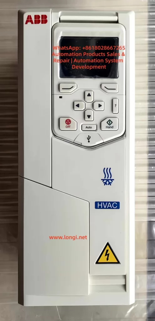
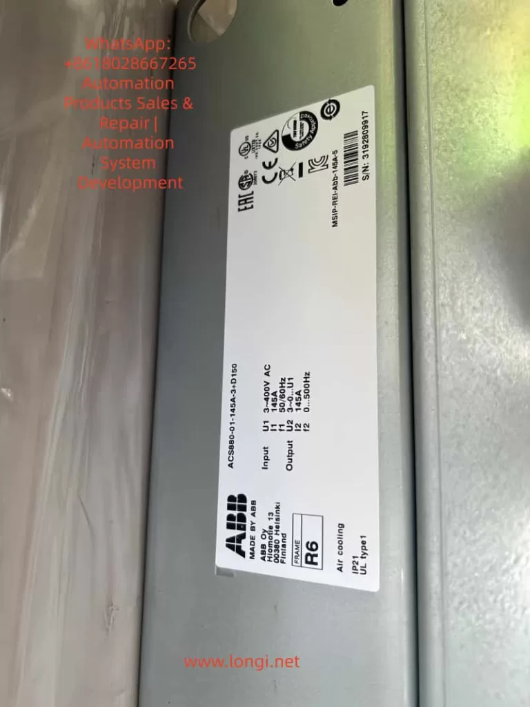
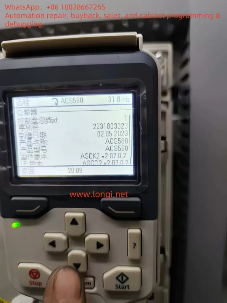
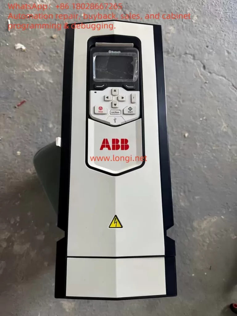
The ACS580 is a high-performance product in the ABB general-purpose drive series, designed specifically for industrial applications. It supports a power range of 0.75 kW to 500 kW and is suitable for 380 – 480 V AC power supplies. With a modular structure, it features a built-in control panel (ACS-AP-S or ACS-AP-I) for convenient parameter setting and fault diagnosis.
(B) Core Features
- Diverse Control Modes: It supports scalar control and vector control. Scalar control is suitable for simple frequency regulation, while vector control provides precise torque and speed control. In hydraulic presses, torque control is often combined with scalar mode to achieve stable pressure.
- Protection Mechanisms: It incorporates a built-in motor thermal model (I²t algorithm) that monitors current, frequency, and time to accumulate heat and prevent overloading. It also supports input from external temperature sensors (such as Pt100 or KTY84) to enhance protection accuracy.
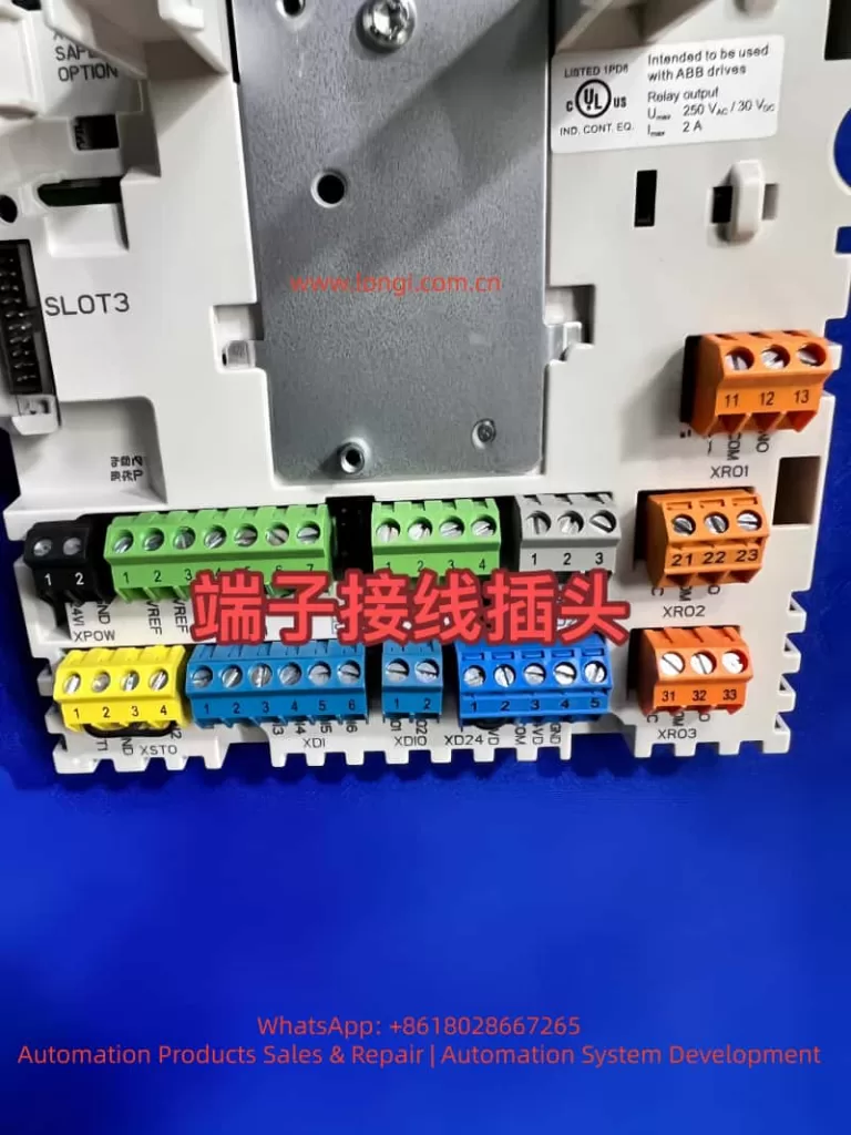
- Communication and Integration: It has a built-in Modbus RTU fieldbus and can be extended to support protocols such as PROFIBUS and EtherNet/IP, facilitating integration with PLCs or upper-level computers.
- Energy Efficiency: The energy optimizer function reduces magnetic flux losses under light loads, saving 1 – 20% of electrical energy. This significantly reduces no-load losses during intermittent operation of hydraulic presses.
(C) Application in Hydraulic Presses
The ACS580 regulates the pump motor’s output through torque control mode to achieve pressure closed-loop control, reducing mechanical components and maintenance costs compared to traditional proportional valve control. It performs excellently in heavy-duty machinery and can handle low-speed, high-load scenarios.
III. Principles of Torque Control Mode
(A) Vector Control
It achieves independent regulation by decoupling the motor’s magnetic flux and torque components. The torque setpoint is calculated by a PI controller, and PWM signals are output to control the inverter. The formula is: T=23×p×LrLm×iq×ψd, where T is the torque, p is the number of pole pairs, iq is the torque current, and ψd is the magnetic flux linkage. This mode offers high precision and is suitable for dynamic loads, but requires ID operation to identify motor parameters.
(B) Scalar Control
It employs simple U/F control, where the voltage is kept proportional to the frequency. Torque is indirectly regulated through current, and it is susceptible to slip at low speeds. The setting of the U/F ratio is crucial. A linear ratio (U∝f) is suitable for constant-torque applications such as hydraulic presses, while a square ratio (U∝f2) is used for variable-torque loads like fans. In the manual, parameter 97.20 (U/F ratio) defaults to linear, but improper user settings (such as setting it to square) can lead to insufficient voltage at low speeds, increased current, and accelerated heat accumulation.
(C) Application Principles in Hydraulic Presses
In hydraulic presses, torque control is used for pressure feedback closed-loop control. Sensors monitor the cylinder pressure, and a PID controller regulates the torque setpoint. Low-speed, high-torque operation is common, and self-cooling motors have poor heat dissipation and are prone to overheating. The control chain is as follows: the setpoint source (AI1/AI2) is selected, processed by a function, and then output through a ramp to a limit module. At low speeds, insufficient magnetic flux (due to U/F mismatch) can cause current peaks and trigger thermal protection. It is necessary to ensure IR compensation in scalar mode to enhance low-frequency torque.
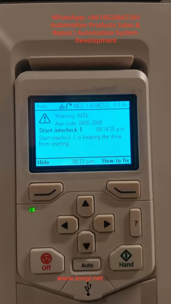
IV. Analysis of the 7122 Fault
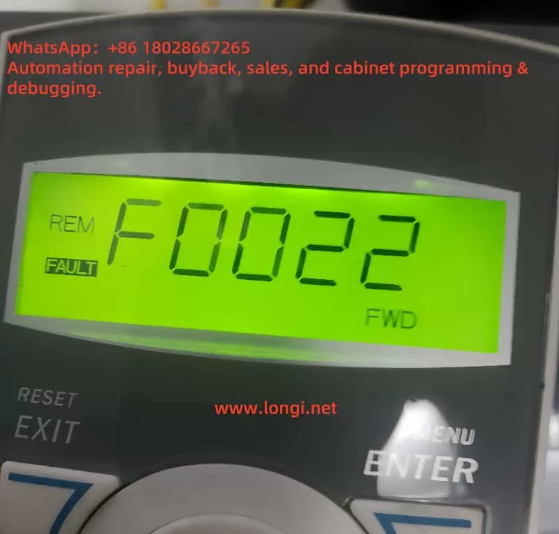
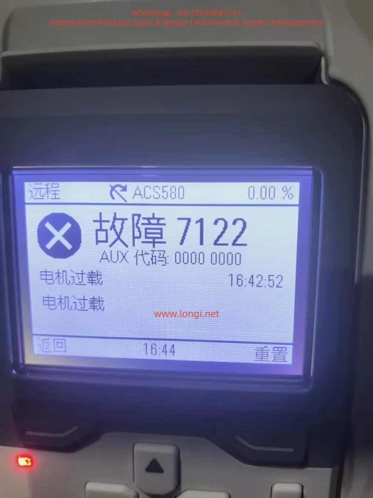
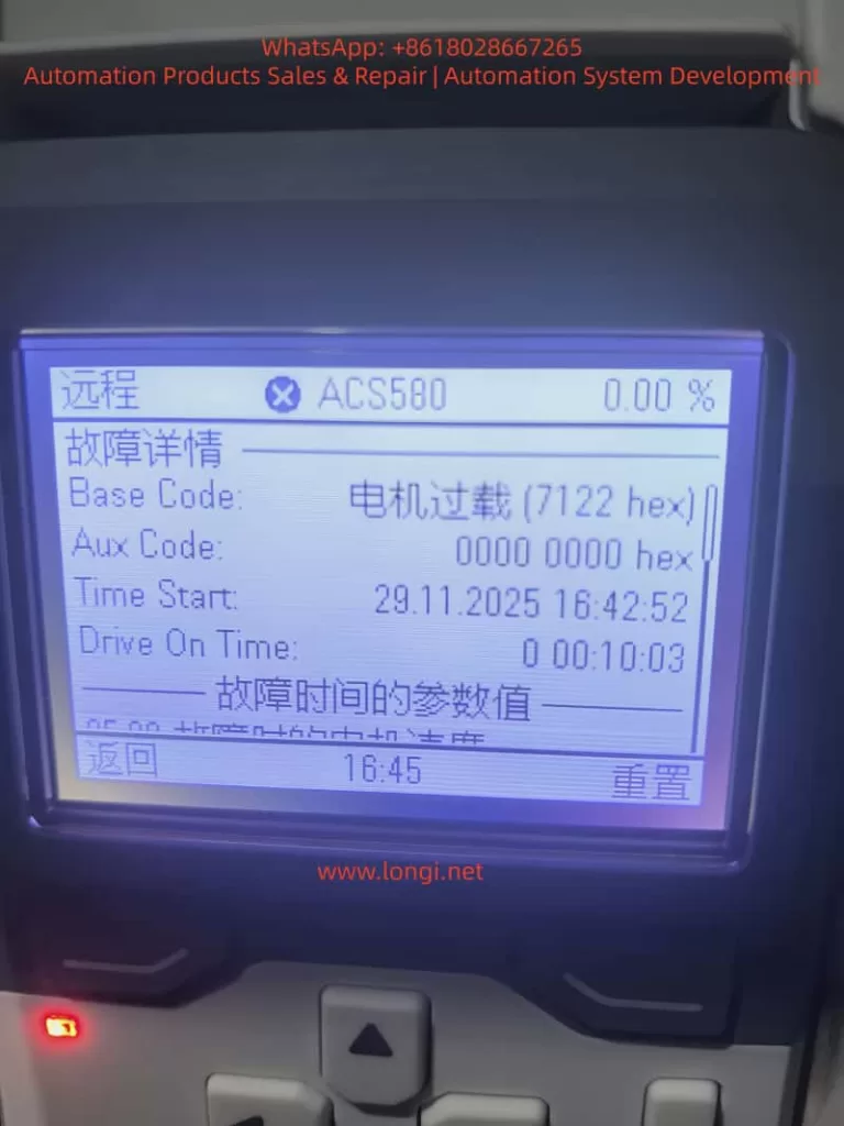
(A) Fault Definition
The 7122 fault indicates motor overload, which occurs when the temperature calculated by the drive’s thermal model exceeds the threshold. Even when the torque is less than 80%, accumulated heat can trigger the fault. According to the manual, it is based on the I²t algorithm, which monitors the integral of current squared over time. When the motor overload level (parameter 35.05) reaches 100%, a trip occurs.
(B) Fault Causes
- Thermal Model Mechanism: The model uses parameters 35.51 (zero-speed load, default 70%), 35.52 (corner frequency, 50 Hz), and 35.53 (corner load, 100%) to define the load curve. At low speeds, the allowable load decreases linearly to the zero-speed value. The formula is: Allowable load = Zero-speed load + (Corner load – Zero-speed load) × (f / f_corner), where f is the current frequency. When users operate at low speeds with a sustained torque close to the allowable value, heat accumulation can trigger the fault.
- Application Mismatch: Hydraulic presses operate at low speeds with high torque, and cooling is often insufficient. Setting the U/F to square results in low voltage at low frequencies, requiring higher current to maintain torque and increasing heat losses.
- Conservative Parameters: Users may set parameters such as 35.51 and 35.52 too loosely, but overestimating the ambient temperature (parameter 35.54) accelerates heat accumulation. Additionally, large errors in sensorless estimation can also contribute to the problem.
- External Factors: High ambient temperatures, blocked motor ventilation, and cable problems can amplify the risk. The 7122 fault is often caused by incorrect motor data or sudden load changes.
V. Case Study
(A) Parameter Analysis
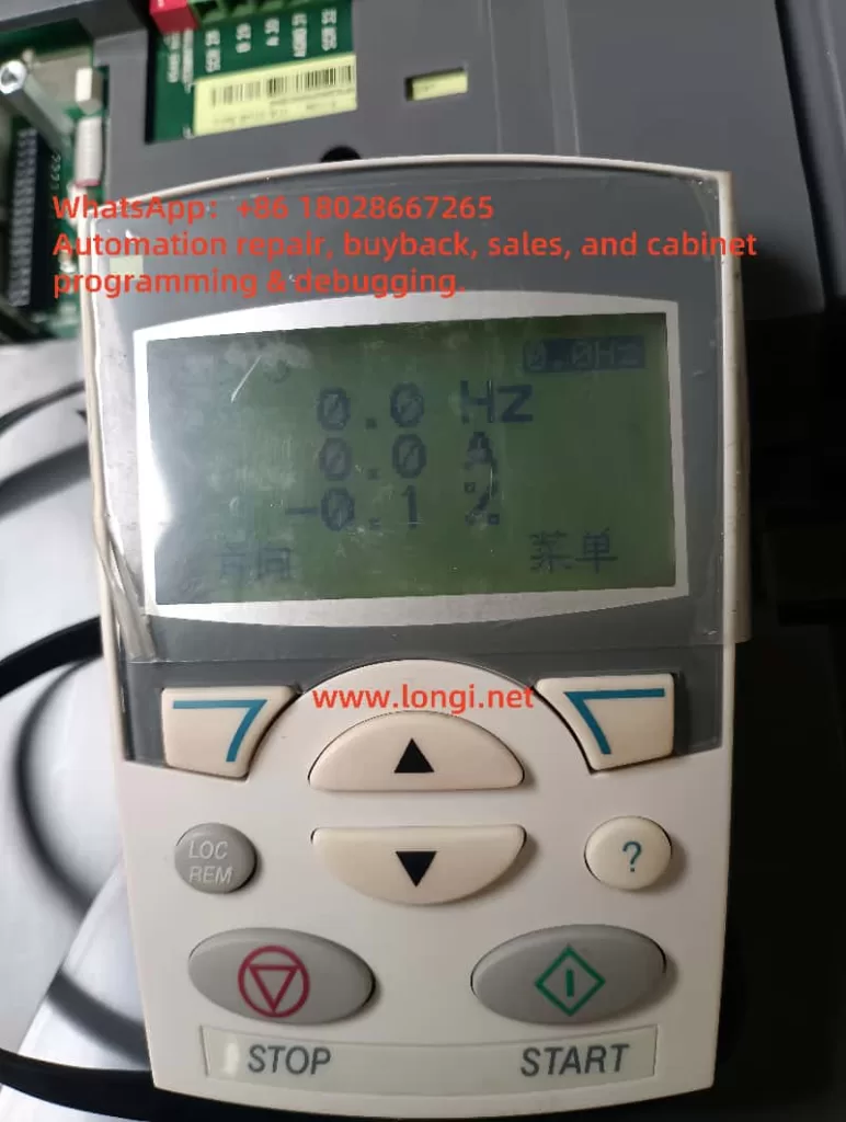
Based on the user-provided parameter photos, the motor data is as follows: 99.04 = scalar, 99.06 = 69.6 A, 99.07 = 380 V, 99.10 = 1450 rpm, and power = 37 kW. The control mode: 19.12/19.16 = torque, 26.11 = AI1. Thermal protection: 35.51 = 130%, 35.52 = 80%, 35.54 = 90°C, 35.57 = Class 30. U/F: 97.20 = square. The operating data shows a torque of 80%, a speed of 300 rpm, and a current of 56.3 A. The thermal model reaches 100% after 10 minutes of fault occurrence.
(B) Problem Diagnosis
The square U/F setting results in high current at low speeds, and the overestimated ambient temperature setting accelerates the I²t accumulation. At 10 Hz, the allowable load = 80% + (130% – 80%) × (10/50) = 90%, and the actual 80% exceeds the limit, leading to accumulation and triggering the 7122 fault, which is often caused by low-speed overloading. To resolve this, the load curve and U/F settings need to be adjusted.
VI. Parameter Optimization Guide
(A) Check Motor Data
Check the motor data in group 99 to ensure it matches the nameplate specifications and avoid underestimating the rated current. Set 99.04 = vector (requires ID operation) to improve accuracy.
(B) Adjust the U/F Ratio
Set 97.20 = linear to ensure sufficient magnetic flux at low speeds. The formula is U=Un×(f/fn)+IR compensation (97.13 = 10 – 20%).
(C) Optimize Thermal Protection
- 35.51 Corner load: Increase from 130% to 150% (if forced cooling is available).
- 35.52 Zero-speed load: Increase from 80% to 90%.
- 35.53 Corner frequency: Decrease from 50 Hz to 30 Hz to expand the high-load area.
- 35.55 Thermal time constant: Increase from 256 s to 500 s.
- 35.56 Overload action: Change from fault to warning (monitor without tripping).
- 35.57 Overload class: Set to Class 30 (highest).
- Enable sensor: Set 35.11 = KTY84 and connect it to AI.
(D) Monitoring and Testing
Monitor parameter 35.05 during operation. If it exceeds 88%, issue a warning and optimize the curve. Use Drive Composer to record data.
(E) Other Optimizations
- Match the torque limits (30.19/30.20) to the application requirements.
- Enable the energy optimizer (45.11 = allow) to save energy.
- After adjustment, restart and test, observing for 10 minutes to ensure no faults occur.
VII. Best Practices and Prevention
(A) Temperature Monitoring
Prioritize the use of external sensors to avoid estimation errors.
(B) Load Matching
When selecting equipment, ensure that the VFD power is at least 1.5 times that of the motor and consider low-speed derating.
(C) Maintenance
Regularly clean the ventilation and check the cables. Use automatic reset (31.12) to handle intermittent faults.
(D) Software Tools
Use Drive Composer to diagnose the thermal curve and simulate optimizations.
(E) Green Applications
VFDs can reduce energy consumption by 20%. Combined with PFC multi-pump control, they can optimize hydraulic systems.
VIII. Conclusion
The 7122 fault in the ACS580’s torque control for hydraulic presses mainly stems from heat accumulation and parameter mismatch. By optimizing group 35 and group 97 parameters, the fault can be effectively resolved, ensuring stable operation. This strategy improves production efficiency, reduces energy consumption, and promotes green manufacturing. In practical applications, it is necessary to combine field testing and, if necessary, consult ABB support.