Introduction
A Variable Frequency Drive (VFD) is an electronic device that controls the speed of an AC motor by adjusting the power supply’s frequency and voltage. It is widely used in industrial automation, energy management, and mechanical equipment control. The Yuxin L Series Inverter is a high-performance product known for its reliability and user-friendliness. This guide provides detailed instructions on using the inverter, covering the operation panel functions, terminal-based forward/reverse control, external potentiometer frequency adjustment, fault codes, and troubleshooting methods. The aim is to help users quickly master the device and utilize it effectively.
Part 1: Operation Panel Functions
The operation panel is the primary interface for interacting with the Yuxin L Series Inverter, enabling parameter configuration, status monitoring, and fault resetting. This section details the panel’s functionalities and specific settings.
1.1 Panel Layout and Button Functions
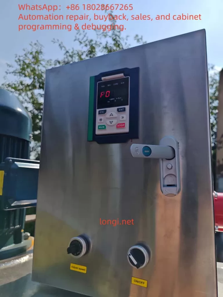
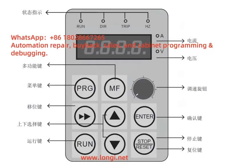
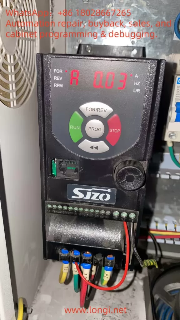
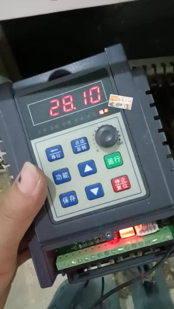
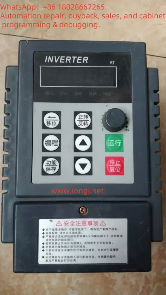
The Yuxin L Series Inverter’s operation panel typically features an LCD display and several function buttons. The display shows operational status, parameter numbers, parameter values, and fault codes. Common buttons and their functions include:
- MENU/ESC: Enter or exit the parameter setting menu.
- UP/DOWN: Navigate the menu or adjust parameter values.
- ENTER: Confirm selections or save parameter settings.
- RUN: Start the inverter’s operation.
- STOP/RESET: Stop the inverter or reset a fault condition.
Users are advised to familiarize themselves with the panel layout and refer to the manual’s panel diagram to ensure accurate operation.
1.2 Restoring Factory Settings
In cases such as incorrect parameter configurations or the need for reinitialization, restoring the inverter to factory settings may be necessary. Follow these steps:
- Press the MENU/ESC button to access the main menu.
- Use the UP/DOWN buttons to locate the “Parameter Management” or similar option (refer to the manual for the exact name).
- Press ENTER to enter the submenu.
- Select the “Restore Factory Settings” option.
- Press ENTER to confirm. The inverter will reset all parameters to their default values.
- Wait for the display to indicate completion, typically taking a few seconds.
Note: Restoring factory settings will erase all custom parameters. Back up important data beforehand.
1.3 Setting and Clearing a Password
To prevent unauthorized parameter changes, the Yuxin L Series Inverter supports password protection. Below are the steps to set and clear a password:
Setting a Password
- Navigate to the “Parameter Management” menu.
- Locate the “Password Setting” option.
- Press ENTER and input a 4-digit password (e.g., “1234”).
- Press ENTER to save. The password will take effect.
- The next time you access parameter settings, the password will be required.
Clearing a Password
- Enter the “Password Setting” menu.
- Input the current password for verification.
- Set the password value to “0000” or leave it blank (check the manual for specifics).
- Press ENTER to save, and the password will be cleared.
Tip: If you forget the password, restoring factory settings may be required, but this will also reset other parameters.
1.4 Parameter Access Restrictions
Parameter access restrictions allow locking specific parameters to prevent accidental or unauthorized modifications. The process is as follows:
- Access the “Parameter Management” menu.
- Select the “Parameter Lock” or similar option.
- Specify the parameter group to lock (e.g., advanced parameters or specific function parameters).
- Set the lock status (typically “1” for locked, “0” for unlocked).
- Press ENTER to save.
- If a password is set, it will be required to modify locked parameters.
This feature allows flexible control over parameter accessibility, ensuring safe operation.
Part 2: Terminal-Based Forward/Reverse Control and External Potentiometer Frequency Adjustment
The Yuxin L Series Inverter supports terminal-based control and frequency adjustment, enabling precise motor control. This section explains how to implement forward/reverse control and frequency adjustment using an external potentiometer, including wiring and parameter settings.
2.1 Terminal-Based Forward/Reverse Control
Terminal-based forward/reverse control is a common method for applications requiring external switches or PLC control.
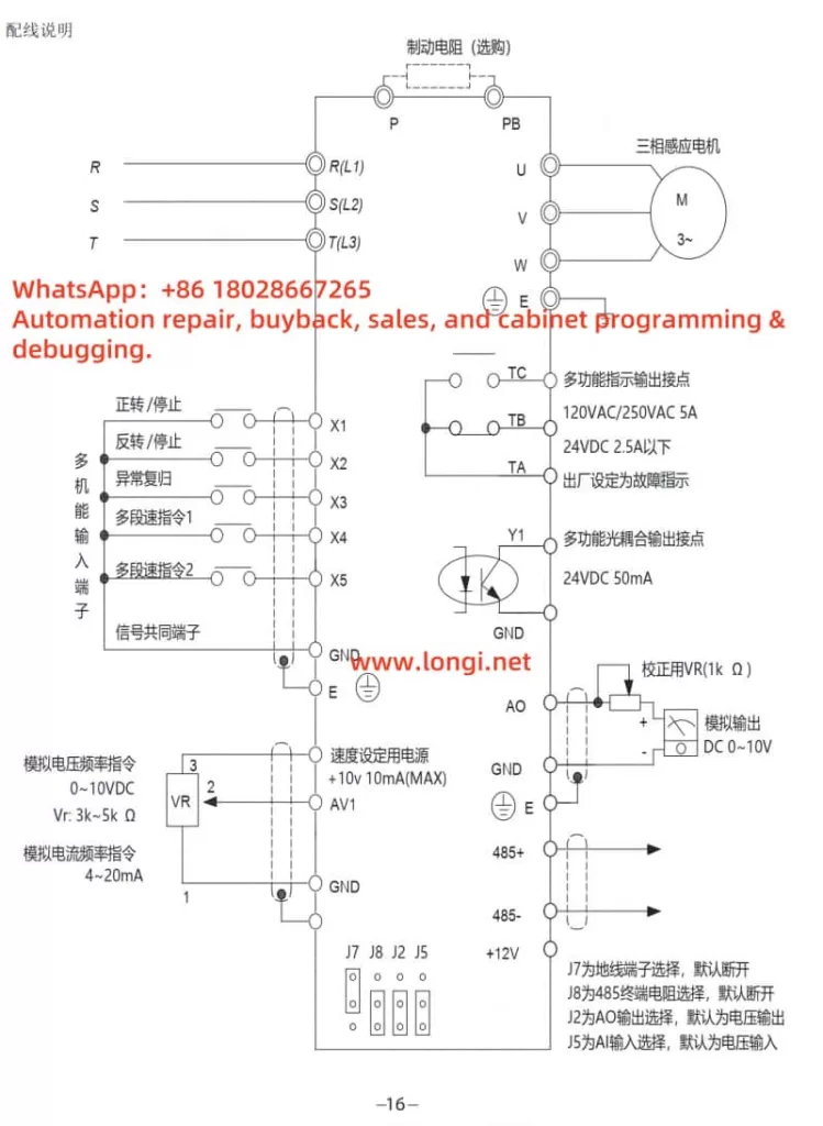
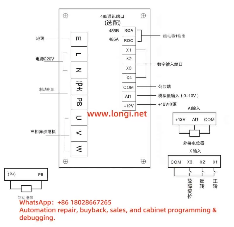
Wiring Method
- Connect the forward switch to the digital input terminal DI1 and the common terminal COM.
- Connect the reverse switch to the digital input terminal DI2 and the common terminal COM.
- Ensure secure connections and refer to the manual’s terminal layout diagram to confirm terminal positions.
Parameter Settings
- Set parameter P0.01 (Control Mode) to “1” to select terminal control mode.
- Set parameter P4.00 (DI1 Function) to “1” to designate DI1 as the forward run command.
- Set parameter P4.01 (DI2 Function) to “2” to designate DI2 as the reverse run command.
- Save the settings. Closing the DI1 switch initiates forward rotation, and closing the DI2 switch initiates reverse rotation.
Note: Parameter numbers may vary by model. Refer to the manual’s parameter table for accuracy.
2.2 External Potentiometer Frequency Adjustment
Using an external potentiometer for frequency adjustment allows smooth speed control, ideal for applications requiring manual adjustments.
Wiring Method
- Connect the potentiometer’s center tap to the analog input terminal AI1.
- Connect one end of the potentiometer to the +10V terminal (provides reference voltage).
- Connect the other end to the GND terminal (ground).
- Use an appropriate potentiometer (typically 10kΩ) and ensure correct wiring.
Parameter Settings
- Set parameter P0.03 (Frequency Reference Source) to “2” to select analog input AI1 for frequency setting.
- Verify parameter P4.10 (AI1 Input Range) matches the potentiometer’s voltage range (typically 0-10V).
- Save the settings. Rotating the potentiometer adjusts the output frequency.
Tip: If the frequency adjustment range is not as expected, adjust related parameters (e.g., maximum frequency P0.11).
Part 3: Fault Codes and Troubleshooting
During operation, the inverter may encounter faults, displayed as fault codes on the screen. This section lists common fault codes and their solutions, but refer to the manual’s fault list for specific codes.
3.1 Common Fault Codes and Solutions
- E001: Overcurrent
- Possible Causes: Excessive motor load, short acceleration time, or incorrect motor wiring.
- Solutions:
- Check motor wiring for short circuits or poor connections.
- Reduce the load or increase the acceleration time (parameter P0.12).
- Restart the inverter to check if the issue resolves.
- E002: Overvoltage
- Possible Causes: High input voltage, short deceleration time, or braking unit failure.
- Solutions:
- Verify the power supply voltage is within the specified range.
- Extend the deceleration time (parameter P0.13).
- If frequent, check the braking resistor for proper function.
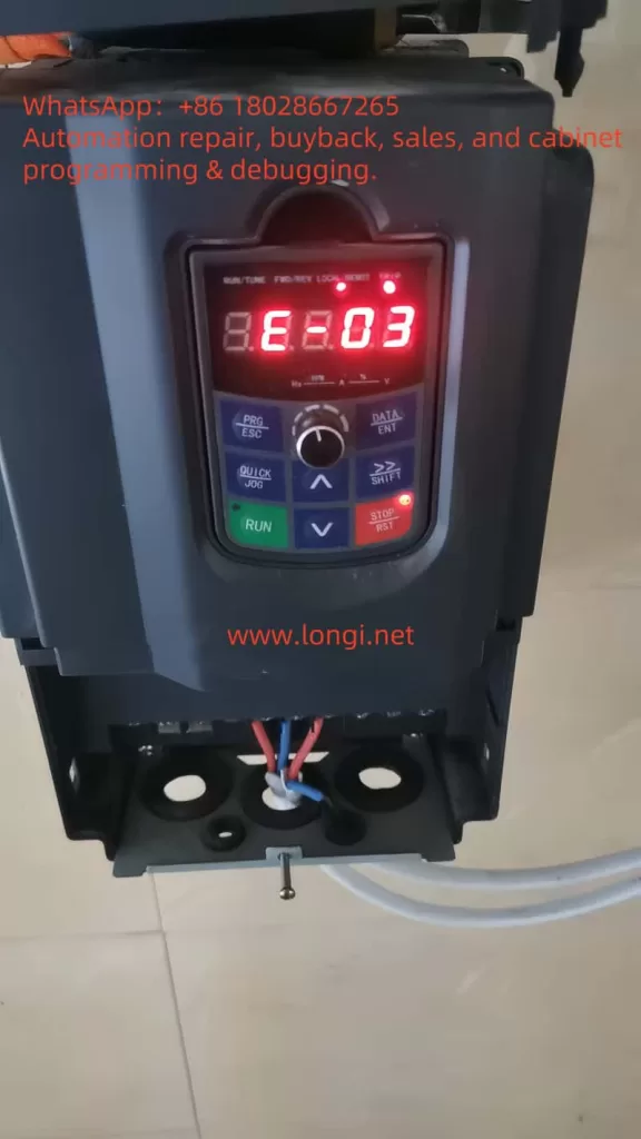
- E003: Undervoltage
- Possible Causes: Low power supply voltage or unstable power.
- Solutions:
- Ensure the input power voltage is stable.
- For multiple devices, confirm adequate power supply capacity.
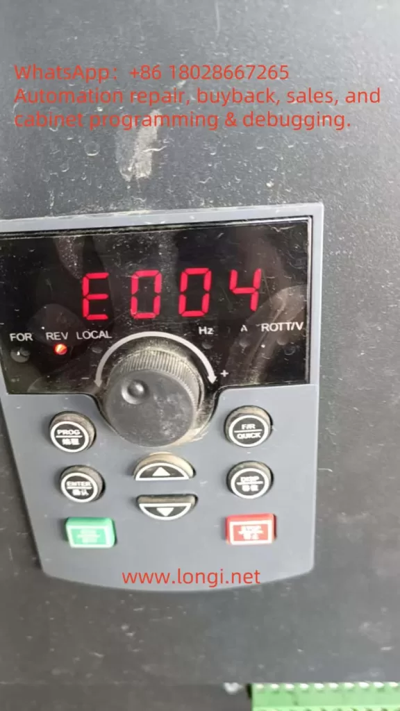
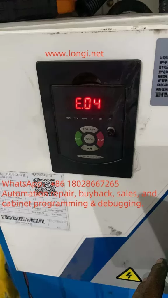
- E004: Motor Overload
- Possible Causes: Excessive load or incorrect motor parameter settings.
- Solutions:
- Reduce the load or select a motor with higher power capacity.
- Verify motor parameters (P1 group) match the actual motor.
- E005: Inverter Overheating
- Possible Causes: High ambient temperature or blocked/faulty cooling fan.
- Solutions:
- Improve ventilation and reduce ambient temperature.
- Clean the fan and heatsink to ensure proper cooling.
3.2 General Troubleshooting Steps
- Record the fault code and consult the manual for its specific meaning.
- Inspect wiring, power supply, and load conditions to rule out external issues.
- Press STOP/RESET to attempt a reset. If unsuccessful, power cycle the inverter.
- If the issue persists, contact technical support with detailed fault information.
Conclusion
The Yuxin L Series Inverter offers robust functionality and flexible configuration, making it an excellent choice for motor control applications. This guide has detailed the operation panel’s usage, terminal-based control and frequency adjustment methods, and fault troubleshooting procedures. Due to model variations and application complexity, users should always refer to the official Yuxin L Series Inverter Manual for precise details. By mastering these foundational skills, you can fully leverage the inverter’s capabilities, enhance equipment efficiency, and address potential issues promptly.