I. Product Overview
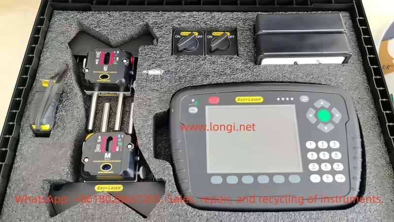
The Easy-Laser E420 is a laser-based shaft alignment system designed specifically for the alignment operations of horizontally and vertically installed rotating machinery, such as pumps, motors, gearboxes, etc. This system utilizes high-precision laser emitters and Position Sensitive Detectors (PSDs) to capture alignment deviations in real-time and guides users through adjustments with intuitive numerical and graphical interfaces. This guide combines the core content of the user manual and provides detailed explanations on equipment composition, operation procedures, functional settings, and maintenance to help users fully master the usage methods of the device.
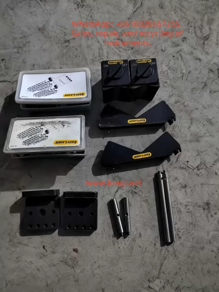
II. Equipment Composition and Key Components
System Components
- Measurement Units (M Unit and S Unit): Installed on the fixed end and the movable end respectively, transmitting data via wireless communication.
- Display Unit E53: Equipped with a 5.7-inch color backlit display, featuring a built-in lithium battery that supports up to 30 hours of continuous operation.
- Accessory Kit: Includes shaft brackets, chains, extension rods (60mm/120mm), measuring tapes, power adapters, and data management software, etc.
Technical Specifications
- Resolution: 0.01 mm (0.5 mil)
- Measurement Accuracy: ±5µm ±1%
- Laser Safety Class: Class 2 (power <0.6mW)
- Operating Temperature Range: -10°C to +50°C
- Protection Rating: IP65 (dustproof and waterproof)
III. Equipment Initialization and Basic Settings
Display Unit Operation
- Navigation and Function Keys: Use the directional keys to select icons or adjust values, and the OK key to confirm operations. Function key icons change dynamically with the interface, with common functions including returning to the previous level, saving files, and opening the control panel.
- Status Bar Information: Displays the current unit, filtering status, battery level, and wireless connection status.
- Screen Capture: Press and hold the “.” key for 5 seconds to save the current interface as a JPG file, facilitating report generation.
Battery and Charging Management
- Charging Procedure: Connect the display unit using the original power adapter and charge up to 8 measurement units simultaneously via a distribution box.
- Low Battery Alert: An LED red light flashes to indicate the need for charging, a green light flashes during charging, and remains lit when fully charged.
- Temperature Considerations: The charging environment should be controlled between 0°C and 40°C, with faster charging speeds in the off state.
System Settings
- Language and Units: Supports multiple languages, with unit options for metric (mm) or imperial (mil).
IV. Detailed Measurement Procedures
Horizontal Alignment (Horizontal Program)
- Installation Steps: Fix the S unit on the stationary machine and the M unit on the movable machine, ensuring relative positional offset. Align the laser beams with the targets on both sides using adjustment knobs. When using wireless functionality, search for and pair the measurement units in the control panel.
- Measurement Modes:
- EasyTurn™: Allows recording three measurement points within a 40° rotation range, suitable for space-constrained scenarios.
- 9-12-3 Mode: Requires recording data at the 9 o’clock, 12 o’clock, and 3 o’clock positions on a clock face.
- Result Analysis: The interface displays real-time horizontal and vertical offsets and angular errors, with green indicators showing values within tolerance ranges.
Vertical Alignment (Vertical Program)
- Applicable Scenarios: For vertically installed or flange-connected equipment.
- Key Parameter Inputs: Include measurement unit spacing, bolt quantity (4/6/8), bolt circle diameter, etc.
- Adjustment Method: Gradually adjust the machine base height and horizontal position based on real-time values or shim calculation results.
Softfoot Check
- Purpose: To check if the machine feet are evenly loaded, avoiding alignment failure due to foundation distortion.
- Operation Procedure: Tighten all anchor bolts. Sequentially loosen and retighten individual bolts, recording detector value changes.
- Result Interpretation: Arrows indicate the machine tilt direction, requiring shim adjustments for the foot with the largest displacement.
V. Advanced Functions and Data Processing
Tolerance Settings (Tolerance)
- Preset Standards: Based on rotational speed分级 (e.g., 0–1000 rpm corresponds to a 0.07mm offset tolerance), users can also customize tolerance values.
File Management
- Saving and Exporting: Supports saving measurement results as XML files, which can be copied to a USB drive or associated with equipment data via barcodes.
- Favorites Function: Save commonly used machine parameters as “FAV” files for direct recall later.
Filter Adjustment (Filter)
- Function: Suppresses reading fluctuations caused by temperature variations or vibrations.
- Setting Recommendations: The default value is 1, typically using levels 1–3 for filtering, with higher values providing greater stability but taking longer.
Thermal Compensation (Thermal Compensation)
- Application Scenarios: Compensates for height changes due to thermal expansion during machine operation. For example, when thermal expansion is +5mm, a -5mm compensation value should be preset in the cold state.
VI. Calibration and Maintenance
Calibration Check
- Quick Verification: Use a 0.01mm tolerance to lift the measurement unit by 1mm using shims and verify if the readings match the actual displacement.
Safety Precautions
- Laser Safety: Never look directly into the laser beam or aim it at others’ eyes.
- Equipment Warranty: The entire unit comes with a 3-year warranty, but the battery capacity warranty period is 1 year (requiring maintenance of at least 70% capacity).
- Prohibited Scenarios: Do not use in areas with explosion risks.
VII. Troubleshooting and Technical Support
Common Issues
- Unstable Readings: Check for environmental temperature gradients or airflow influences, and increase the filtering value.
- Unable to Connect Wireless Units: Ensure that the units are not simultaneously using wired connections and re-search for devices in the control panel.
Service Channels
- Equipment must be repaired or calibrated by certified service centers. Users can query global service outlets through the official website.
VIII. Conclusion
The Easy-Laser E420 significantly enhances the efficiency and accuracy of shaft alignment operations through intelligent measurement procedures and intuitive interactive interfaces. Users should strictly follow the manual steps for equipment installation, parameter input, and result analysis, while making full use of advanced functions such as file management and thermal compensation to meet complex operational requirements. Regular calibration and standardized maintenance ensure long-term stable operation of the equipment, providing guarantees for industrial equipment safety.