In modern industrial automation systems, the inverter is the core device for motor control and energy-saving operations. It is widely used in pumps, fans, compressors, and various mechanical transmission systems. Among them, the Yaskawa V1000 inverter has become a popular choice due to its compact design, high reliability, and stable performance.
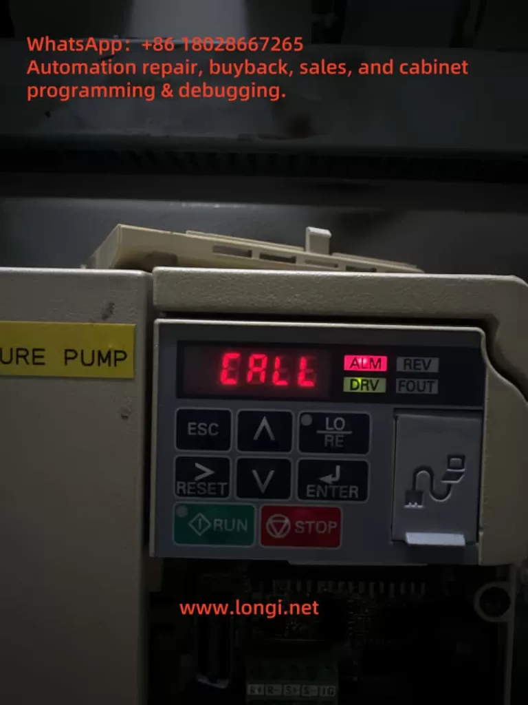
However, during field operation, many users encounter a situation where the inverter’s keypad displays “CALL”, while the ALM (alarm) indicator is lit. For beginners, this situation may seem confusing—“CALL” is often mistaken as a call instruction or program recall. In reality, it represents a communication-related warning.
This article will analyze the meaning of the CALL alarm, its possible causes, troubleshooting methods, and preventive measures, offering a structured guide to help engineers resolve this problem effectively.
2. Meaning of CALL Alarm
On Yaskawa V1000 inverters, CALL means “Communication Awaiting”.
When the inverter is set to communication control mode, it continuously waits for data from the master device (PLC, PC, or communication module).
If no valid data is received within a specific time, the inverter enters the CALL state.
In this case, the ALM LED turns on, indicating a minor fault (warning). Unlike a trip fault, it does not immediately stop the inverter but signals that communication has not been established correctly.
Therefore, CALL is not a severe error code, but a reminder that the communication link is inactive or faulty.
3. Main Causes of CALL Alarm
Based on Yaskawa’s official manual and field experience, the CALL warning is generally triggered by the following issues:
1. Incorrect communication wiring
Improper connection of RS-485 or MECHATROLINK cables, short circuits, loose connections, or broken wires will cause communication failure.
2. Master device program not running or faulty
If the PLC or PC is not transmitting communication commands, the inverter will always remain in the CALL state.
3. Communication circuit malfunction
Damaged communication modules, defective ports, or strong external interference may disrupt data transmission.
4. Improper termination resistor setting
In Modbus/MEMOBUS or MECHATROLINK systems, termination resistors must be installed at both ends of the communication line. Incorrect settings lead to unstable signals and communication errors.
5. Incorrect control mode settings
If the inverter is configured to communication mode (e.g., o2- parameters set to serial communication) but no master is connected, it will always display CALL.
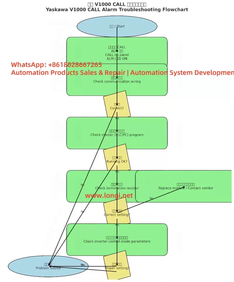
4. Troubleshooting Steps
When the inverter shows CALL with ALM lit, the following step-by-step procedure is recommended:
Step 1. Check wiring
Verify RS-485 polarity (A/B terminals).
Ensure shielded twisted pair cables are used and grounded properly.
Inspect for loose, shorted, or broken wires.
Step 2. Check the master device
Confirm that the PLC or PC communication port is enabled.
Ensure that the master continuously transmits communication commands (e.g., Modbus function codes, MECHATROLINK frames).
Debug the ladder program to confirm proper command output.
Step 3. Check termination resistors
Install a 120Ω resistor at both ends of the communication line.
If the V1000 has an internal switch for termination resistance (e.g., S2 switch), ensure it is set to ON.
Step 4. Verify inverter parameters
Confirm o2- parameters (control mode selection).
If communication is not required → set the mode to panel or terminal control.
If communication is required → ensure correct baud rate, parity, and slave address settings.
Step 5. Power cycle test
After corrections, restart the inverter.
If CALL disappears, the issue is solved.
If it persists, consider replacing the keypad, communication module, or contacting Yaskawa technical support.
5. Case Studies
Case 1: Wiring error
A water pump system using PLC + V1000 in communication control showed CALL constantly. Upon inspection, RS-485 polarity was reversed. Correcting the wiring resolved the issue immediately.
Case 2: Master program inactive
In a production line upgrade, V1000 inverters were linked by Modbus. Since the PLC program had not been downloaded yet, all inverters displayed CALL. Once the master program was activated, the alarms cleared.
Case 3: Termination resistor missing
In a long-distance bus network, multiple V1000 units showed CALL alarms. Investigation revealed no termination resistors were installed. Adding 120Ω resistors at both ends solved the communication problem.
6. Preventive Measures
To avoid recurring CALL alarms, engineers should adopt the following best practices:
Standardized wiring
Always use shielded twisted pair cables.
Properly ground the shield layer to reduce interference.
Reliable master program
Ensure PLC/PC programs send communication frames immediately after startup.
Include heartbeat signals to prevent timeouts.
Correct termination resistor setup
Always place resistors at both ends of the communication line.
Verify onboard termination switch settings.
Control mode configuration
If communication is not required, set the inverter to terminal or panel control to prevent unnecessary CALL states.
If communication is required, confirm all protocol settings match between master and slave devices.
Regular maintenance
Periodically inspect cable connections and terminal blocks.
Check communication bus health in multi-inverter systems.
7. Conclusion
The CALL alarm on Yaskawa V1000 inverters is essentially a communication waiting warning, not a critical trip. It indicates that the inverter is not receiving valid data from the master device.
By systematically checking wiring, master device operation, termination resistors, and control parameters, engineers can quickly identify and resolve the issue. Moreover, if communication is not used, simply switching to panel or terminal control mode will prevent the CALL alarm.
Understanding CALL’s meaning and mastering troubleshooting procedures not only reduces downtime but also enhances the reliability of the overall automation system.
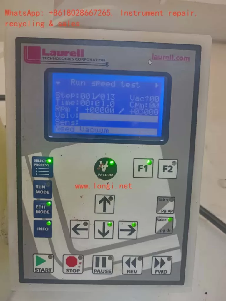
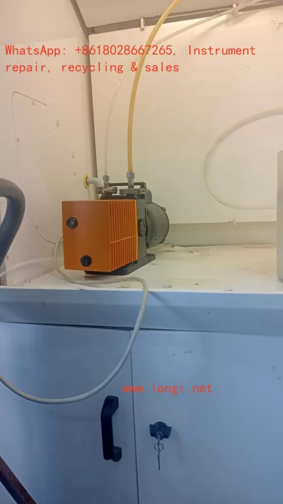
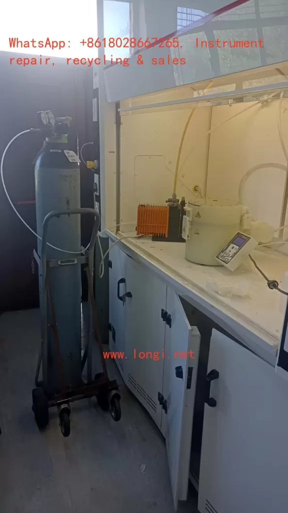
Spin coaters are critical tools in microfabrication, material science, and semiconductor laboratories. They rely on high-speed rotation to uniformly spread photoresists or other coating materials onto wafers, glass slides, or substrates. One of the most commonly used systems in this category is the Laurell Technologies spin coater series.
A built-in safety interlock system ensures that the sample does not fly off during rotation. This is achieved by using a vacuum chuck, which secures the wafer or substrate via suction. If the machine does not detect a valid vacuum signal, it will refuse to start the spin cycle and display the warning message:
“Need Vacuum”
This safety feature prevents dangerous accidents and sample loss. However, in some situations, operators may encounter a scenario where:
The sample is firmly held by the vacuum chuck, indicating that the vacuum suction is working.
But the controller display still shows “Need Vacuum”, and the motor will not rotate.
This contradiction is exactly the case observed by the customer in South Africa, as shown in the photos and video evidence provided.
In this article, we will thoroughly analyze the issue, explain why it happens, and provide a structured troubleshooting guide for engineers, technicians, and laboratory users.
2. How the Vacuum Interlock Works in Laurell Spin Coaters
To understand the problem, one must first understand the design of the vacuum interlock system:
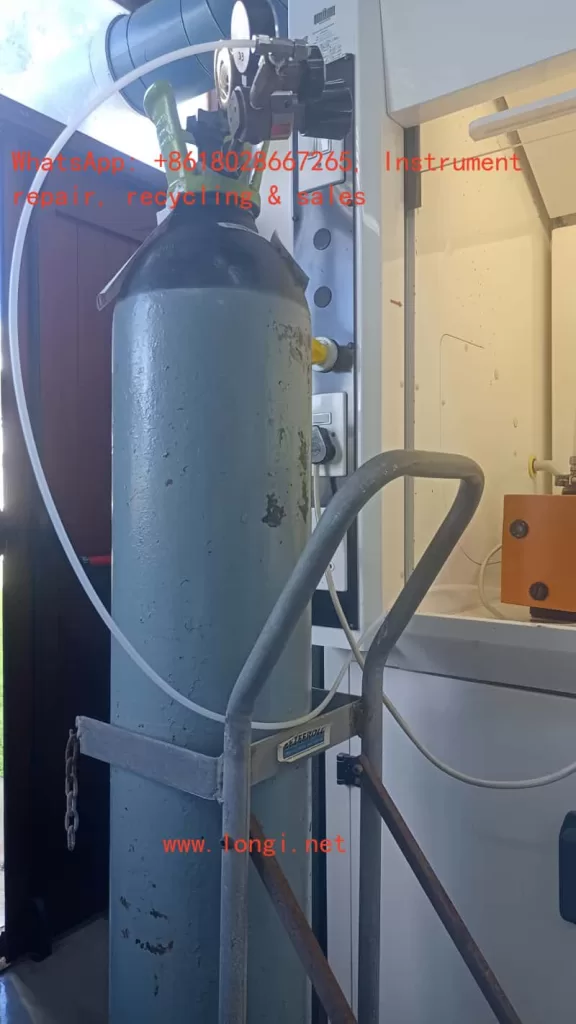
Vacuum Source
Usually provided by an external vacuum pump.
In some labs, a central vacuum line is available.
The pump draws negative pressure through tubing connected to the spin coater chuck.
Vacuum Chuck
A flat plate with small holes that holds the sample by suction.
When the pump is active, the wafer is tightly fixed to the chuck surface.
Vacuum Sensor or Switch
Located inside the spin coater.
Detects whether the vacuum level is sufficient for safe operation.
Sends a signal (ON/OFF or analog voltage) to the controller board.
Controller Logic
If the vacuum sensor indicates “No Vacuum,” the motor remains locked.
If vacuum is detected, the program is allowed to start spinning.
Thus, the machine requires both physical vacuum suction AND a valid signal from the sensor.
3. Symptom Observed by the Customer
From the photos and video provided, the following facts were established:
The sample (a square substrate) is securely attached to the chuck during vacuum operation.
The vacuum pump and tubing system are operational, as suction is clearly holding the substrate.
Despite this, the Laurell controller display shows “Need Vacuum” and the spin motor does not activate.
The operator is stuck at Step 00 in the spin program, unable to proceed further.
This mismatch between actual vacuum state and controller feedback is the root cause of the complaint.
4. Possible Causes of the Problem
4.1 Vacuum Sensor Malfunction
The vacuum sensor inside the coater may have failed.
Even though negative pressure exists, the sensor does not detect or report it.
Sensors can fail due to aging, contamination, or internal electrical faults.
4.2 Wiring or Connection Issues
The electrical signal from the sensor to the main control board may be interrupted.
Loose connectors, broken wires, or corrosion can cause signal loss.
A perfectly working vacuum will not be recognized if the signal path is broken.
4.3 Blocked or Misrouted Sensor Line
In some Laurell models, the sensor has its own dedicated small tubing.
If this line is blocked, pinched, or not connected to the correct port, the sensor will not see the vacuum.
Meanwhile, the chuck still holds the wafer properly.
4.4 Controller I/O Board Failure
The sensor might be functional, but the control board input channel is defective.
The vacuum detection signal never registers in the system.
4.5 Incorrect Parameter or Setup Configuration
Laurell systems allow configuration of Vacuum Interlock settings.
If the interlock is mistakenly disabled or misconfigured, the machine logic can behave unexpectedly.
For example, the controller might be waiting for a different signal threshold than what the sensor provides.
5. Evidence from the Video
The customer’s video shows:
At the beginning, the wafer is firmly attached to the vacuum chuck.
The operator gently touches or shakes it, and it stays in place.
This proves that vacuum suction is indeed active.
However, the spin coater does not proceed with rotation, confirming that the problem lies in signal recognition, not actual suction.
This video evidence eliminates issues like:
Faulty vacuum pump.
Leaking tubing.
Improper wafer placement.
Therefore, the focus must shift to detection, feedback, and controller logic.
6. Step-by-Step Troubleshooting Guide
Step 1: Confirm Vacuum Pump Operation
Ensure the pump is turned on.
Measure vacuum level at the pump output with a gauge (should meet Laurell’s specifications).
Step 2: Verify Chuck Suction
Place a sample or even a flat piece of glass.
If it is firmly held, the vacuum path from pump → tubing → chuck is confirmed.
Step 3: Inspect Sensor Tubing (if applicable)
Some models use a separate small tube leading to the vacuum sensor.
Make sure it is not disconnected, clogged, or leaking.
Step 4: Check Sensor Signal
Disconnect the electrical connector from the sensor.
Measure output with a multimeter when vacuum is applied.
If the signal does not change, the sensor is defective.
Step 5: Test Wiring Integrity
Use continuity testing on the wiring harness from sensor to controller.
Repair or replace cables if broken.
Step 6: Bypass/Short Test (For Verification Only)
Short the sensor signal input to simulate “vacuum present.”
If the machine starts spinning, the controller is fine but the sensor or wiring is faulty.
Step 7: Check Controller Settings
Access the system configuration menu.
Verify that Vacuum Interlock is enabled and thresholds are correct.
If necessary, temporarily disable interlock for diagnostic purposes (not recommended for normal operation).
Step 8: Controller Board Diagnosis
If sensor and wiring are confirmed good, the controller input board may be defective.
Replacement or repair of the I/O board is required.
7. Practical Recommendations
Replace the vacuum sensor if it shows no electrical response under suction.
Check and secure wiring connectors to eliminate intermittent signals.
Clean the sensor line to remove possible blockages.
Review the configuration in the Laurell menu to ensure interlock is properly set.
Contact Laurell service if controller hardware is suspected faulty.
8. Why This Problem Matters
This situation highlights an important principle in equipment maintenance:
Mechanical performance does not guarantee electrical recognition.
Even though the vacuum holds the wafer physically, the safety system relies on an independent electrical or pneumatic feedback mechanism.
If the feedback loop is broken, the machine assumes unsafe conditions and refuses to operate.
Such protective interlocks are common in high-speed rotating machinery, where user safety must always be prioritized.
9. Conclusion
The South African customer’s Laurell spin coater issue is a textbook case where vacuum is physically present, but the system still displays “Need Vacuum.”
The video clearly shows that the wafer is tightly held, ruling out pump or chuck problems.
Therefore, the most probable causes are vacuum sensor failure, wiring disconnection, or controller input malfunction.
A systematic troubleshooting procedure should start from confirming sensor response, checking wiring, and reviewing interlock settings, before finally suspecting controller board faults.
Ultimately, the problem is not the vacuum itself, but the failure of the machine to recognize and accept the vacuum signal.
By following the structured troubleshooting flowcharts and step-by-step guide, laboratory staff can isolate the fault, repair it effectively, and restore the spin coater to full working condition.
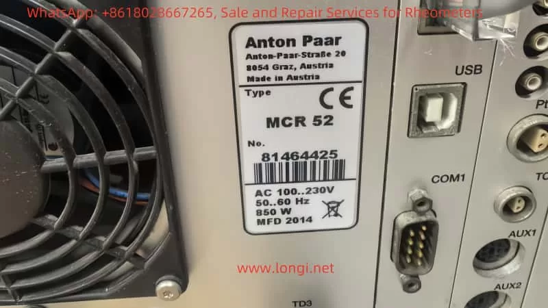
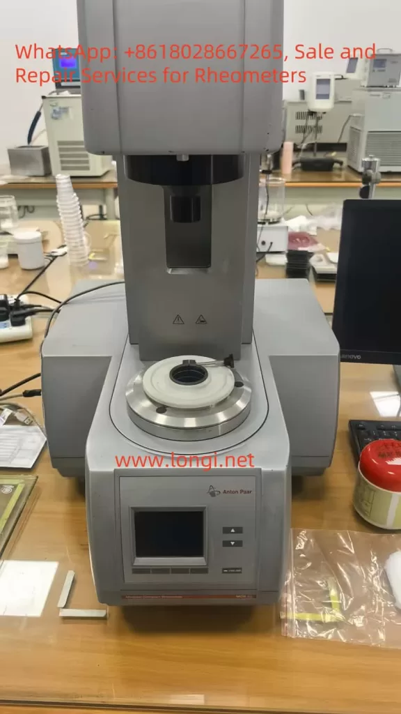
In the automotive industry, PVC sealing adhesives are widely used for seam sealing, underbody protection, and surface finishing. Their typical formulation includes polyvinyl chloride (PVC), plasticizers such as diisononyl phthalate (DINP), inorganic fillers like nano calcium carbonate, and thixotropic agents such as fumed silica. These materials exhibit strong thixotropy and yield stress behavior, which are critical for application performance: they must flow easily during application but quickly recover structure to maintain thickness and stability afterward.
Rheological testing, particularly the determination of Bingham parameters (yield stress τ₀ and plastic viscosity ηp), is a key method for evaluating flowability and stability of such adhesives. However, in practice, it is common to encounter the problem that repeated tests on the same PVC adhesive sample yield very different Bingham viscosity values. In some cases, customers suspect that the rheometer itself may be faulty.
This article systematically analyzes the main causes of poor repeatability, including sample-related issues, operator and method-related factors, and potential instrument malfunctions. Based on the Anton Paar MCR 52 rheometer, it also provides a structured diagnostic and troubleshooting framework.
I. Bingham Viscosity and Its Testing Features
1. The Bingham Model
The Bingham plastic model is a classical rheological model used to describe fluids with yield stress: τ=τ0+ηp⋅γ˙\tau = \tau_0 + \eta_p \cdot \dot{\gamma}
where:
τ = shear stress
τ₀ = yield stress
ηp = Bingham (plastic) viscosity
γ̇ = shear rate
The model assumes that materials will not flow until shear stress exceeds τ₀, and above this threshold the flow curve is approximately linear. For PVC adhesives, this model is widely applied to describe their application-stage viscosity and yield properties.
2. Testing Considerations
Only the linear region of the flow curve should be used for regression.
Pre-shear and rest conditions must be standardized to ensure consistent structural history.
Strict temperature control and evaporation prevention are required for repeatability.
II. Common Causes of Poor Repeatability in Bingham Viscosity
The variability of results can arise from four categories: sample, operator, method, and instrument.
1. Sample-Related Issues
Formulation inhomogeneity: uneven dispersion of fillers or thixotropic agents between batches.
Bubbles and inclusions: entrapped air leads to noisy stress responses.
Evaporation and skin formation: solvents volatilize during testing, increasing viscosity over time.
Thixotropic rebuilding: variations in rest time cause different recovery levels of structure.
2. Operator-Related Issues
Loading technique: inconsistent trimming or sample coverage affects shear field.
Geometry handling: inaccurate gap, nonzero normal force, or loose clamping.
Temperature equilibration: insufficient time before testing.
Pre-shear conditions: inconsistent shear strength or rest period.
3. Methodological Issues
Regression region: including nonlinear low-shear regions distorts ηp.
Dwell: 20–30 s per point or steady-state criterion.
Discard first loop; fit second loop linear region (10–100 s⁻¹).
5. Data Processing
Report τ₀ and ηp with R² ≥ 0.98.
Document regression range and hysteresis.
6. Quality Control
Target repeatability: CV ≤ 5% for ηp (≤8% for highly thixotropic samples).
Use standard oils or internal control samples daily.
V. How to Verify If the Instrument Is Faulty
When customers suspect a rheometer malfunction, simple tests with Newtonian fluids can clarify:
Zero-drift check
Run empty for 10–15 min; torque baseline should remain stable.
Standard oil repeatability
Load the same Newtonian oil three times independently.
Target: viscosity CV ≤ 2%, R² ≥ 0.99.
Temperature step test
Measure at 23 °C and 25 °C; viscosity should change smoothly and predictably.
Geometry swap
Compare results using PP25/SR and CC27; Newtonian viscosity should agree within ±2%.
Air supply check
Confirm correct pressure, dryness, and filter condition for the air bearing.
If the standard oil also shows poor repeatability, then instrument malfunction is likely. Probable causes include:
Torque transducer failure/drift.
Air-bearing instability.
Temperature control faults.
Normal force or gap detection errors.
Disabled compliance/inertia compensation.
VI. Communication Guidelines with Customers
Eliminate sample and method factors first: the thixotropy, volatility, and wall slip of PVC adhesives are usually the dominant causes of poor repeatability.
Verify instrument health with standard oils: if oil results are consistent, the instrument is healthy and SOP must be optimized; if not, escalate to service.
Provide an evidence package: standard oil data, zero-point stability logs, temperature records, air supply parameters, geometry and gap information, and compensation settings.
Conclusion
Automotive PVC sealing adhesives are complex materials with strong thixotropic and yield stress behavior. In rheological testing, poor repeatability of Bingham viscosity can be attributed to sample properties, operator inconsistencies, methodological flaws, or instrument faults.
By applying a standardized SOP—including vane or serrated geometry, strict temperature control, controlled pre-shear and rest times, and regression limited to the linear region—repeatability can be significantly improved.
To determine whether the instrument is at fault, repeatability checks with Newtonian standard oils provide the most objective method. If results remain unstable with standard oils, instrument issues such as torque transducer drift, air-bearing instability, or temperature control errors should be suspected.
Ultimately, distinguishing between sample/method effects and instrument faults is essential for efficient troubleshooting and effective communication with customers.
— Practical Application of DriveExecutive Software with USB-DSI Adapter
1. Introduction
In the field of industrial automation, variable frequency drives (VFDs) play a central role in motor control and energy efficiency. Among them, the Allen-Bradley PowerFlex family from Rockwell Automation is widely recognized for its reliability, flexibility, and robust communication options.
This article focuses on the PowerFlex 400 drive (e.g., Cat No. 22C-D142A103) and demonstrates how to use DriveExecutive software together with a USB-to-DSI communication adapter to perform parameter diagnostics, upload/download operations, and fault analysis. By combining hardware setup, software configuration, and troubleshooting techniques, this guide provides a complete workflow for engineers working in the field.
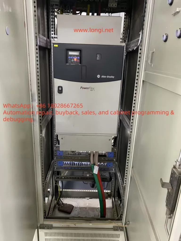
2. Overview of the PowerFlex 400
The PowerFlex 400 is a VFD designed specifically for fan and pump applications. Its main characteristics include:
Voltage class: 380–480V three-phase input;
Power range: from 3 kW to 250 kW, with the case in this article being 75 kW (100 HP);
Built-in communication: standard RS485 (DSI) port, expandable to Modbus, EtherNet/IP, DeviceNet, and others;
Application features: optimized PID control for HVAC and pumping systems, built-in bypass logic, and energy-saving functions.
3. Diagnostic Needs in the Field
Typical on-site requirements for engineers include:
Reading and backing up all drive parameters;
Monitoring real-time operating data such as voltage, current, frequency, and load;
Modifying parameters for control mode tuning or PID loop optimization;
Accessing fault and alarm history for troubleshooting.
To accomplish these tasks efficiently, a reliable PC-based diagnostic tool is essential. The combination of DriveExecutive software and a USB-to-DSI adapter is one of the most recommended solutions.
4. Required Hardware and Software
Hardware
PowerFlex 400 VFD (e.g., Cat No. 22C-D142A103);
USB-to-DSI communication adapter (1203-USB is the official Rockwell option; third-party compatible adapters may also work);
A Windows PC or laptop;
Proper cabling (USB to PC, DSI end to the drive’s RS485 port).
Software
RSLinx Classic: Rockwell’s official communication driver software, required for all connections;
DriveExecutive: the parameter management and diagnostic tool used to interact with the drive.
5. Step-by-Step Connection Procedure
1. Physical Connection
Plug the USB-to-DSI adapter into the PC;
Connect the other end of the adapter to the PowerFlex 400’s DSI port (typically marked R+, R-, COM);
Ensure the drive is powered on.
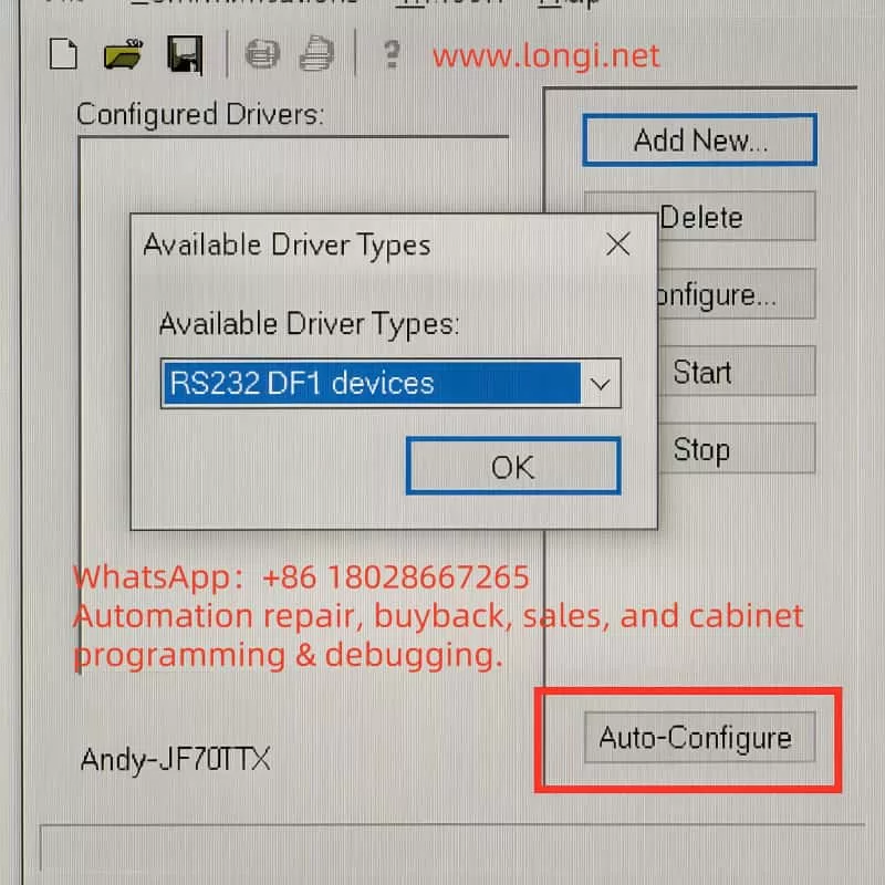
2. Configuring RSLinx Classic
Open RSLinx Classic;
Navigate to Communications → Configure Drivers…;
Add a new driver:
For the original 1203-USB: choose USB-DF1 Devices;
For third-party USB-RS485 adapters: choose RS232 DF1 Devices;
Select the correct COM port for the adapter;
Click Auto-Configure. If the message “Successfully configured” appears, communication is established.
3. Connecting with DriveExecutive
Launch DriveExecutive;
From the menu, select Drive → Connect;
Choose RSLinx as the communication path;
Browse for the device and locate PowerFlex 400 [Node Address];
Click to connect and enter the parameter view.
6. Troubleshooting Common Issues
Adapter not recognized
Ensure the USB driver for the adapter is installed;
Check Windows Device Manager to confirm the virtual COM port is created.
Auto-Configure fails
Verify proper wiring to the DSI port, paying attention to polarity of R+ and R-;
Ensure the baud rate matches the default setting (typically 19.2 kbps).
DriveExecutive cannot detect the drive
Confirm that RSLinx RSWho can see the drive node;
If visible in RSLinx but not in DriveExecutive, refresh the communication path or check software licensing.
Unstable third-party adapter
Some non-official adapters may cause unreliable communication. For critical or long-term use, the official 1203-USB adapter is strongly recommended.
7. Practical Applications and Benefits
With the setup described above, engineers can perform the following tasks effectively:
Parameter upload and download: simplifying commissioning and backup;
Real-time monitoring: displaying drive data such as current, output frequency, and DC bus voltage;
Fault diagnostics: quickly identifying root causes by reviewing alarm and fault logs;
Remote support: when paired with VPN or remote desktop tools, parameter diagnostics can be carried out off-site, minimizing downtime.
In large-scale pump stations and building automation systems, this workflow greatly improves efficiency and reliability in maintenance operations.
8. Conclusion
The PowerFlex 400 is a well-established drive optimized for fan and pump loads. In practice, engineers often need to back up, monitor, and adjust parameters while troubleshooting on-site. By combining DriveExecutive software, RSLinx Classic, and a USB-to-DSI adapter, a comprehensive solution for diagnostics and communication is achieved.
For occasional parameter access, third-party USB-RS485 cables may suffice. However, for professional and long-term industrial use, the official 1203-USB adapter ensures maximum stability and compatibility.
As industrial systems evolve toward Ethernet-based communication (EtherNet/IP), USB-to-DSI solutions may gradually be phased out. Nevertheless, given the large installed base of PowerFlex 400 and similar models, this approach remains highly practical and relevant in today’s fieldwork.
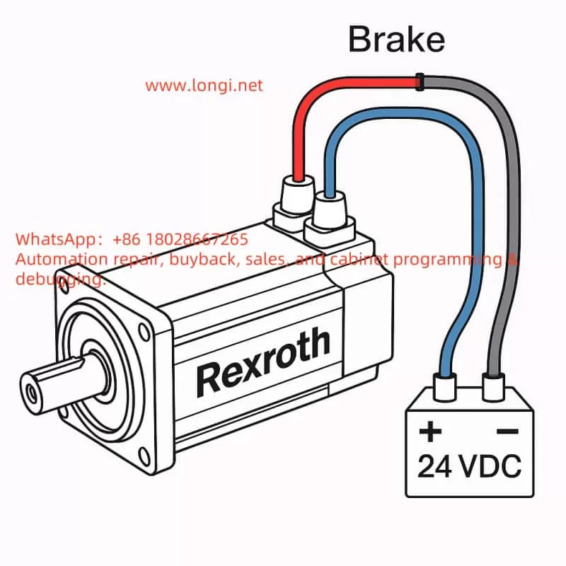
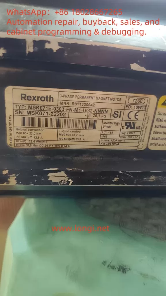
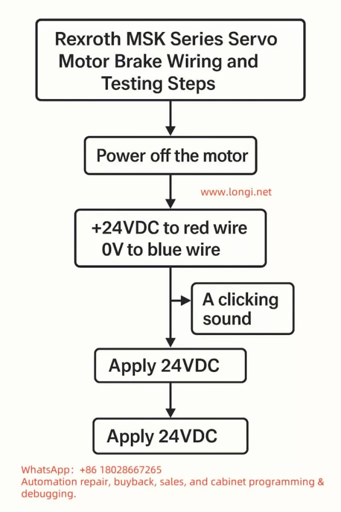
Nameplate Parameters: Brake 30Ω, DC 24V ±10%, 0.94A 👉 Indicates that this motor is equipped with a DC brake, rated for a working voltage of 24VDC, which releases the brake when powered and locks it when de-energized.
2. Wiring Identification
Red Wire → +24VDC
Blue Wire → 0V (Negative)
(Gray Wire Pair) = Temperature Sensor, not involved in brake testing.
3. Power Supply Preparation
Use a regulated 24VDC power supply with a rated current of ≥2A (reserve a margin, although normal operation requires approximately 1A).
The power supply should have overcurrent protection to prevent damage from short circuits.
If possible, it is best to use a power supply with soft start or current limiting functions.
4. Testing Steps
Disconnect the motor and confirm that the motor’s main power supply is not connected.
Connect the positive terminal of the power supply to the red wire and the negative terminal to the blue wire.
Apply 24VDC power:
You should hear a “click” sound, indicating that the brake has been released.
Gently rotate the motor shaft by hand; it should rotate freely.
Disconnect the 24VDC power supply:
Attempt to rotate the motor shaft again; it should be locked by the mechanical brake.
5. Precautions
Never operate the motor shaft for extended periods with the brake continuously powered without control from a motor driver, as excessive inertia from shaft rotation may damage the brake pads.
In practical applications with a driver, the brake signal is usually controlled by the driver’s Brake Output; do not continuously apply direct power.
If the brake fails to release, check the following:
Whether the power supply voltage is within 24V ±10%.
Whether the power supply current is sufficient.
Whether the red/blue wires are reversed (reversing them will prevent release).
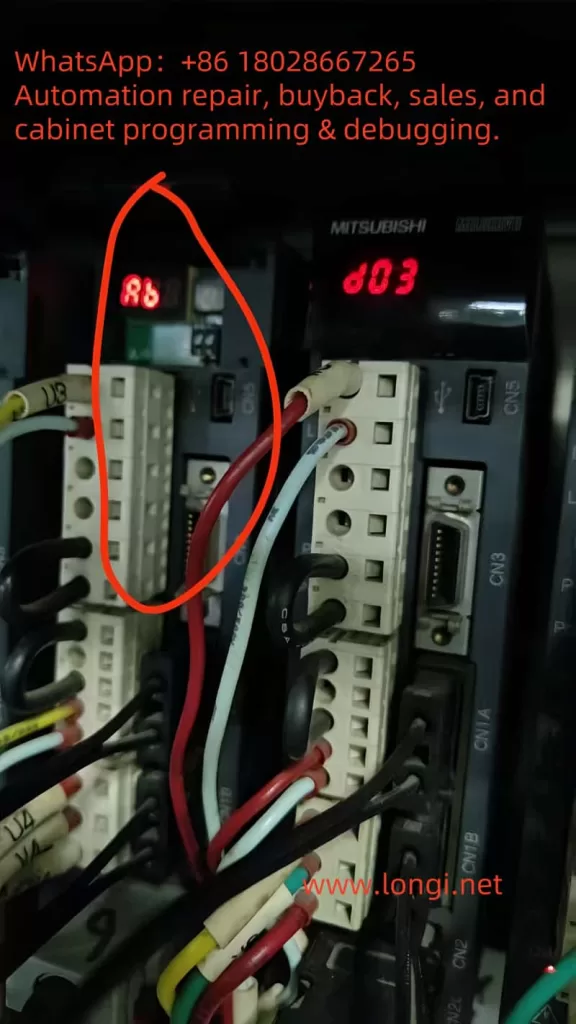
The Mitsubishi Electric MR-J3-B series servo amplifiers are precision control devices widely used in industrial automation, primarily for driving servo motors to achieve high-precision positioning, speed control, and torque control. Renowned for their high responsiveness, reliability, and ease of integration, these products are suitable for applications such as CNC machine tools, robotic arms, and printing machinery. However, during actual use, users often encounter various codes on the display, with the “Ab” display being a common initialization status indicator. According to official manuals and user feedback, “Ab” is not strictly an alarm code (Alarm) but rather a status display indicating that the servo amplifier is in the initialization phase or experiencing communication issues. Ignoring this display may result in the system failing to start normally or the motor not responding to commands, thereby affecting production efficiency.
This guide systematically compiles knowledge about the “Ab” display based on Mitsubishi’s official manuals (e.g., MR-J3-B SERVO AMPLIFIER INSTRUCTION MANUAL SH030051G), troubleshooting guides, and user experiences from online forums. The content covers explanations of its meaning, cause analysis, diagnostic methods, solution steps, preventive measures, and practical cases, aiming to provide comprehensive reference for engineers and technicians. Understanding the “Ab” display hinges on its close relationship with the SSCNET III communication protocol, axis number settings, and power sequencing. Through this guide, you will learn how to quickly locate problems and restore system operation. The following content is logically structured to ensure each step is supported by evidence.
Meaning of “Ab” Display and Initialization Process
On the 5-digit 7-segment LED display of the MR-J3-B servo amplifier, “Ab” is a specific initialization status code, not a typical alarm (e.g., “AL.10” indicates undervoltage). According to the official manual (SH030051G, pages 4-6), when the servo amplifier is powered on, if the servo system controller (e.g., PLC or motion controller) is not turned on, the axis number settings do not match, or there is a communication fault, the display will show “Ab”. This indicates that the system is attempting to initialize communication parameters but has failed to complete synchronization.
The initialization process is a multi-stage sequence that typically includes the following display codes:
Ab: Initialization communication phase. The servo amplifier detects that the controller is not responding or the axis numbers are inconsistent. At this point, the system is in the “Ready off” state and cannot enter servo readiness mode.
AC: Synchronization completion phase. If “Ab” quickly switches to “AC”, it indicates that preliminary communication has been established.
Ad: Parameter communication phase. The servo amplifier reads parameter settings from the controller.
AE: Encoder communication phase. Verifies the servo motor encoder signal.
AF: I/O signal communication phase. Checks external input/output signals.
AH: Initialization complete. The system enters normal status, displaying codes such as “b01” (readiness off) or “d01” (servo on).
AA: If the controller is completely turned off, “AA” is displayed, indicating waiting for SSCNET communication to resume.
If the display cycles through “Ab → AC → Ad → Ab”, it indicates a persistent communication error or a fault in the servo system controller (manual, pages 4-6). The manual also mentions that in the revised version of the manual (e.g., July 2007), “Ab.” was corrected to “Ab” to avoid user confusion (Appendix App.-9). Additionally, in the safety version of the manual, “Ab” is closely related to the integrity of the SSCNET III fiber-optic cable. If the cable is disconnected or contaminated, it interrupts optical module operation, causing the rear axis to display “AA” and activating dynamic braking (Section 3-2).
It is important to emphasize that “Ab” is not a fault alarm and therefore does not trigger automatic shutdown or historical records (e.g., parameter PA09 is used to clear alarm history, page 5-24). However, if ignored, it may evolve into actual alarms such as “34” (continuous receive error) or “36” (intermittent receive error), which are related to SSCNET cable issues (pages 8-5 to 8-6). Understanding this process helps distinguish “Ab” from similar displays, such as “rb” (possibly a misreading) or “E6” (overload warning).
Possible Causes of “Ab” Display
The root cause of the “Ab” display usually lies in communication initialization failure, which can be categorized into three main types: power sequencing issues, mismatched settings, and hardware faults. The following provides a detailed analysis based on the manual and user feedback.
Improper Power Sequencing: When the servo amplifier is powered on, if the servo system controller is not turned on first, the amplifier cannot receive control signals, causing initialization to get stuck at the “Ab” stage (manual, page 4-8). In multi-axis systems, if the power to the front-axis amplifier is interrupted, the rear axis will display “AA” and force a stop (Section 3-2). Forum user feedback indicates that this situation is common after system restarts or maintenance, especially when multiple amplifiers share the same power supply.
Mismatched Axis Number Settings: The MR-J3-B uses a rotary axis setting switch (SW1) to define axis numbers, ranging from 0 to F (corresponding to axes 1 to 16). If the axis number set by SW1 does not match the axis number assigned by the servo system controller (e.g., QD75MH positioning module), the system cannot synchronize and displays “Ab” (pages 1-11 and 3-61). The manual warns that in multi-axis SSCNET networks, duplicate axis numbers can cause the entire system to fail (page 3-61). Additionally, in interpolation mode (e.g., X-Y table control), mismatched axis numbers can also affect position loop gain (PB07 parameter, page 6-4).
SSCNET III Communication Hardware Faults: SSCNET III is a fiber-optic communication protocol that is high-speed (150 Mbps) but sensitive to cables. Common issues include:
Disconnected, dirty, damaged, or excessively bent cables, leading to degraded optical characteristics (alarms 34/36, page 8-5).
Noise interference: Electromagnetic noise from nearby power lines or motor cables can intermittently interrupt communication (page 8-6).
Optical module faults: When the control circuit power is turned off, the optical module does not operate, causing communication interruptions (Section 3-2).
USB communication-related issues: If using MR Configurator software for diagnosis, a damaged cable may trigger alarms “8A” or “8E” (Chapter 8).
Other minor causes include loss of absolute position (alarm 25, low battery voltage or origin not set, page 8-3) and parameter errors (alarm 37, page 8-7), which may indirectly cause initialization failures. Forum discussions (e.g., MrPLC.com) report that “Ab” is often associated with loose encoder cables or CPU grounding issues, but the official manual emphasizes the SSCNET level more.
Diagnostic Steps: How to Confirm and Locate the Problem
Diagnosing the “Ab” display requires a systematic approach, combining display observations, software tools, and hardware checks. The following are recommended steps based on Chapter 4 (Startup) and Chapter 8 (Troubleshooting) of the manual:
Observe Display Changes: Record the display sequence after power-on. If it remains fixed at “Ab”, check the controller power supply; if it cycles through “Ab-AC-Ad-Ab”, suspect axis number or communication faults (page 4-6). Use the display navigation buttons to switch to status mode and view motor speed, command pulse frequency, and load rate (page 13-50).
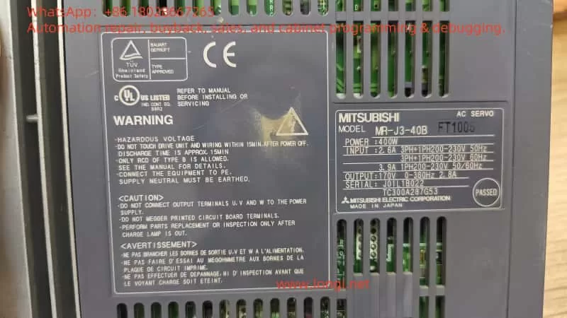
Check Power Supply and Sequencing: Ensure that the servo system controller is powered on first, followed by the amplifier. Verify the input voltage (200-230 V AC, confirmed by the label). Wait 15 minutes for discharge before re-powering (safety precautions, page A-1).
Verify Axis Number Settings: Use the SW1 switch to check the axis number and ensure it matches the controller (page 1-11). In multi-axis systems, verify the SW1 settings for each amplifier individually to avoid duplicates.
SSCNET Cable Diagnosis: Visually inspect the fiber-optic cable for damage, dirt, or excessive bending (minimum bending radius 50 mm, page 3-33). Clean the connector end faces and use noise suppression measures such as ferrite cores (page 8-5). If intermittent errors are suspected, monitor communication at 70 ms intervals (alarm 36).
Software Diagnosis: Connect USB to the CN5 port and use MR Configurator software to read error logs and parameters (page 4-10). The software can simulate JOG operation and positioning tests to confirm encoder signals (page 4-13, set PC05=1 in motorless operation mode).
Environmental and Hardware Checks: Confirm that the ambient temperature (0-55°C), humidity (<90% RH), and vibration (<49 m/s², page A-3) are within specifications. Check grounding, terminal tightness, and regenerative resistor connections (MR-RB series, pages 188-190).
If the diagnosis still shows “Ab”, record the alarm history (parameter PC21, page 13-56) and consult Mitsubishi technical support.
Solutions: Step-by-Step System Restoration
Once the cause is located, resolving the “Ab” display is relatively straightforward. The following are targeted solutions:
Adjust Power Sequencing: Turn on the controller power supply first and wait for stabilization before powering on the amplifier. The manual recommends using the DO forced output function to verify I/O signals (page 4-2).
Correct Axis Numbers: Adjust SW1 to the correct axis number and restart the system. Ensure that axis numbers are unique in multi-axis networks (page 3-61). If interpolation is involved, manually set the PB07 gain to the minimum value (page 6-4).
Repair SSCNET Communication:
Replace or clean cables: Disconnect the power supply and replace damaged cables (page 3-33).
For alarms 34/36, mark the servo as off, disconnect the power supply, use MR Configurator to identify the cause, and ensure safety before resetting (Chapter 8).
Absolute Position-Related Issues: If accompanied by alarm 25, replace the battery (MR-J3BAT), set the origin, and power cycle (page 8-3).
Test Operation: Perform JOG (speed test) or positioning operations in MR Configurator to confirm motor response (page 4-10). Enable forced stop 2 (EM2) to prevent accidents (page 4-4).
Advanced Reset: Clear the alarm history (PA09=1, restart, page 13-56). If the fault persists, consider replacing the amplifier or controller.
User feedback indicates that these steps can resolve over 90% of “Ab” problems, especially the power sequencing adjustments often mentioned in forums, which provide immediate results.
Preventive Measures: Avoiding Recurrence of “Ab” Display
Prevention is better than cure. The following measures are based on the safety and maintenance sections of the manual (pages A-1 to A-3 and Section 2-5):
Standardize Operating Procedures: Develop a power-on sequencing manual to ensure that the controller is turned on first. Provide regular training for operators.
Regular Maintenance: Inspect SSCNET cables, SW1 settings, and environmental conditions quarterly. Monitor battery voltage (>3.0 V) and replace it every 3 years (page 8-3).
Hardware Optimization: Use the recommended cable length (<50 m) and avoid routing near noise sources. Install regenerative resistors (MR-RB) to prevent overloads (page 188).
Software Monitoring: Integrate MR Configurator into daily inspections to view parameters and logs in real time. Set parameter alarm thresholds (e.g., overload warning E1, page 8-10).
Backup and Updates: Back up parameter settings and regularly update manual revisions (e.g., the July 2007 version corrected the display, page App.-9).
These measures can significantly reduce the incidence of “Ab” and improve system reliability.
Practical Case Analysis
Case 1: In a forum discussion, a user reported that an MR-J2S (similar to J3) displayed “AB” due to the controller power being turned off. Solution: Turn on the controller first and restart the amplifier, and the display returned to “d01”. Case 2: Another user had multiple faulty units displaying “Ab”, diagnosed as duplicate axis numbers. Adjusting SW1 resolved the issue and prevented system瘫痪 (system shutdown). Case 3: A video titled “Mitsubishi Quick Tips” demonstrated the “Ab” display along with “b01”, “E6”, etc., emphasizing communication checks. User comments confirmed that cable cleaning was effective. Case 4: In a troubleshooting PDF, communication errors caused the “Ab” display to cycle, and replacing the SSCNET cable restored normal operation.
These cases prove that rapid diagnosis can save downtime.
Conclusion
The “Ab” display is a common indicator during the initialization process of the MR-J3-B servo amplifier, primarily caused by power sequencing, axis number settings, or SSCNET communication issues. Through the systematic analysis in this guide, you can comprehensively understand its meaning and practical troubleshooting methods, from diagnosis to resolution. It is recommended to always refer to the official manual and use MR Configurator tools for diagnosis. If the problem is complex, contact Mitsubishi support promptly. Proper maintenance can not only resolve “Ab” issues but also enhance overall system performance, ensuring efficient industrial production.
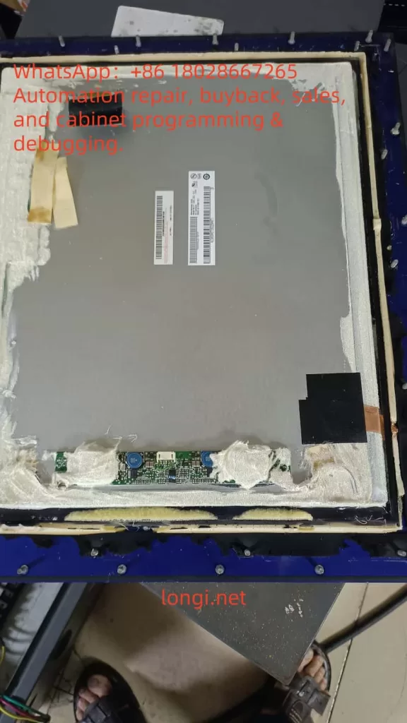
In hazardous environments such as coal mines, petrochemical plants, chemical processing facilities, and oil & gas fields, conventional electronic displays cannot be directly applied. This is because LCD panels and their driver circuits may generate sparks, arcs, or heat during operation, which could ignite surrounding flammable gases or dust. Therefore, specialized explosion-proof displays compliant with ATEX / IECEx standards must be used. These devices feature special designs in their housings, sealing methods, heat dissipation, and internal structures.
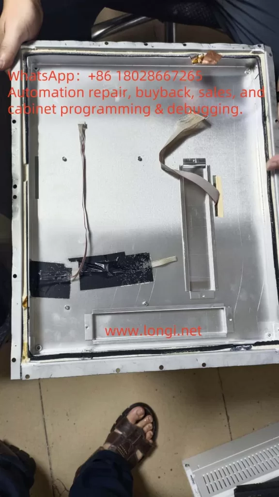
During the repair of a customer’s explosion-proof display, the author discovered something unusual: apart from the LCD module and driver board, the interior was filled with a large quantity of uniform, tiny plastic beads—enough to collect half a bowl after disassembly. At first, the purpose of these beads was unclear, and some speculated that they might be desiccants. However, further investigation revealed that these microbeads play a crucial role in the explosion-proof design. This article explores their functional mechanism, possible material types, and alternative options.
I. Basic Requirements of Explosion-Proof Displays
1. Explosion-Proof Standards
According to the IEC 60079 series of international standards, explosion-proof electrical equipment must prevent the following hazards:
Arc and spark leakage: Switching elements, relays, or LCD driver ICs may generate sparks.
Hot surfaces: LED backlight drivers or power modules may heat up.
Internal explosions: If components burn or fail, flames must not propagate outside the enclosure.
Common protection methods include Flameproof (Ex d), Intrinsic Safety (Ex i), Increased Safety (Ex e), and Powder Filling (Ex q)—the method most relevant to this discussion.
2. The Principle of Ex q Powder Filling
Ex q protection involves filling the enclosure with fine particles or powder so that no free air cavities remain inside. Any arcs, sparks, or flames are effectively blocked from propagation. Typical fillers include quartz sand, glass microbeads, or flame-retardant polymer beads.
Advantages include:
Friction between particles dissipates energy and prevents flame spread.
The filler provides thermal insulation, slowing heat transfer.
Properly selected materials are non-flammable and ensure safety.
II. Observations During Repair
Upon disassembly, it was noted that all housing seams were sealed with adhesive. Inside, the cavity was densely packed with white, spherical beads of about 0.5–1 mm diameter, lightweight and smooth.
Initial suspicion that these might be silica gel desiccants was soon dismissed:
The sheer volume was far beyond what moisture control would require.
Desiccant beads are typically porous and often color-indicating (blue/orange).
Their primary purpose is moisture absorption, not shock absorption or flame suppression.
Thus, these were confirmed not to be desiccants but rather specialized filler beads for explosion-proof applications.
III. Likely Material Types
By comparing common industrial fillers, the beads are most likely one of the following:
1. EPS / EPE Foam Beads
Appearance: White, lightweight, uniform diameter.
Advantages: Excellent energy absorption, cushioning, and vibration damping; inexpensive.
Limitations: Low heat resistance unless treated with flame retardants.
Advantages: Fireproof, high-temperature resistant, widely used in construction insulation.
Limitations: Dust generation, irregular shapes, not suitable for close contact with electronics.
Based on their smooth spherical shape, uniform size, and dense packing, the filler in this display is more consistent with flame-retardant EPS/EPE beads or hollow glass microspheres, rather than perlite-based construction materials.
IV. Functional Mechanism of Beads in Explosion-Proof Displays
1. Energy Absorption
In the event of arcs, short circuits, or small internal explosions, the beads absorb shock energy through inter-particle friction, preventing flame penetration.
2. Elimination of Cavities
By filling every space inside the enclosure, no free air volume remains, reducing the risk of flammable gases accumulating.
3. Thermal Insulation and Flame Retardancy
The filler layer weakens heat conduction. Even if some circuits generate heat, it is not quickly transferred to the housing. Flame-retardant treated beads will not sustain burning.
4. Shock and Vibration Damping
Explosion-proof displays are often installed in environments subject to mechanical vibration. The filler beads protect LCD panels and circuits by cushioning against long-term vibration.
V. Can “Glassy Perlite Beads” Be Used as a Substitute?
Products such as glassy perlite beads (expanded perlite) are commonly sold for construction insulation. While fireproof, they are not suitable substitutes in this context because:
Irregular shapes make them pack poorly, leaving gaps.
High dust levels may contaminate electronic boards.
Low mechanical resilience means they crumble under vibration and do not cushion effectively.
Thus, glassy perlite beads are not recommended as replacements for the original filler.
VI. Suitable Substitutes and Purchasing Advice
1. Flame-Retardant EPS Beads
Recommended size: 1–3 mm diameter.
Advantages: Lightweight, easy to fill, cost-effective.
Requirement: Must meet certified flame-retardant grades (e.g., UL94 V-0 or B1).
Chinese e-commerce: Search for “阻燃EPS微珠” or “中空玻璃微珠”
International suppliers: Brands such as Storopack and SpexLite offer filler beads with technical documentation.
Explosion-proof equipment distributors: Some suppliers provide certified filler material specifically for Ex q applications.
VII. Conclusion
The beads observed inside the explosion-proof display are not desiccants but specialized filler materials that comply with the Ex q powder filling principle (IEC 60079-5). Their functions include absorbing energy, eliminating cavities, insulating against heat, and damping vibration.
Based on observed characteristics, they are most likely flame-retardant EPS/EPE foam beads or hollow glass microspheres, not perlite-based construction fillers. For repairs or replacement, it is critical to choose certified, flame-retardant, low-dust spherical beads, typically 1–3 mm in diameter, to ensure compliance with explosion-proof safety standards.
This choice directly affects not only the reliability of the equipment but also intrinsic safety in hazardous environments. Therefore, service personnel must reference relevant standards and confirm flame-retardant certification when selecting replacement materials.
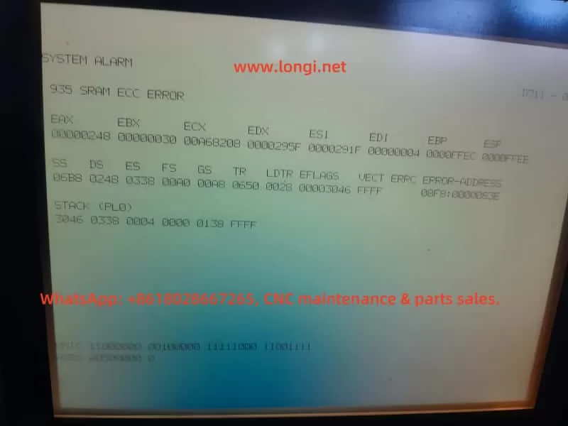
This is one of the more common and serious errors in the Fanuc control system. Let’s analyze the causes and handling directions:
1. Alarm Meaning
SRAM ECC Error: The system has detected a checksum error in the SRAM memory.
ECC (Error Checking and Correction) is an error-detection mechanism. This alarm is triggered when data in the SRAM (battery-backed memory or system RAM) is corrupted.
The alarm code 935 generally indicates:
Corruption of SRAM data bits
Failure of the memory chip itself
Loss of data due to battery power failure or insufficient charge
2. Possible Causes
Damage to the SRAM chip on the motherboard (a common hardware aging issue)
Battery depletion or poor battery contact → Loss of SRAM data
Corruption of parameter files (caused by abnormal shutdowns or interference)
Failure of the control board itself (CNC Main Board)
3. Typical Symptoms
The system fails to start normally (as seen in your video, stuck at the alarm screen).
Repeated reboots may still result in the same alarm.
Occasionally, the system may boot, but all parameters are lost.
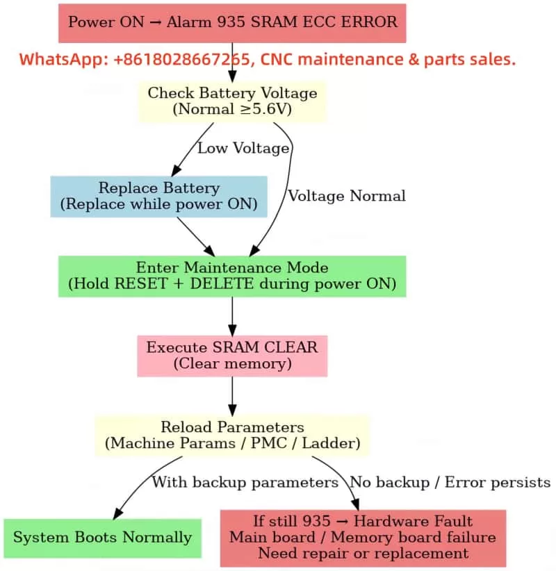
4. Solution Steps
A. Check the Battery
Open the control cabinet and locate the Fanuc SRAM backup battery (usually a lithium battery, 6V or 3V × 2 in series).
Measure the voltage. If it is < 5.6V (for a 6V battery) or < 2.9V (for a single 3V battery), it must be replaced.
When replacing, ensure the controller remains powered (to avoid data loss due to power failure).
B. Attempt to Clear SRAM and Reinitialize
Enter the system maintenance mode (BOOT/INITIALIZE).
Execute SRAM CLEAR (clear the memory).
Reload the PMC Ladder, system parameters, and machine parameters.
Requires backup parameters provided by the original machine tool manufacturer (important!)
C. If the Error Persists After Clearing
There is a high probability of a hardware failure in the motherboard’s SRAM.
The motherboard (CNC board/Memory Board) needs to be replaced.
Experienced maintenance engineers may attempt to replace the SRAM chip, but replacing the entire board is generally more reliable.
5. Recommended Immediate Actions for This Problem
First, check the battery voltage → If the battery voltage is low, replace the battery and attempt to power on again.
If the battery is normal → Enter maintenance mode, clear the SRAM, and reload the parameters.
If the error persists after clearing → It is likely a motherboard hardware failure, requiring repair or replacement.
⚠️ Note:
Clearing the SRAM will result in the loss of machine tool parameters. Always have a backup file (from a CF card, PC card, or obtained from the manufacturer).
Without parameter backups, even if the error is cleared, the machine tool cannot be restored to normal operation.
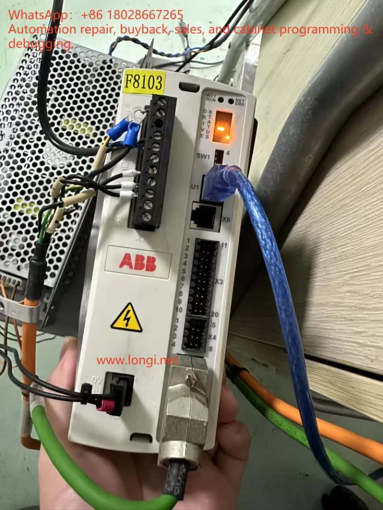
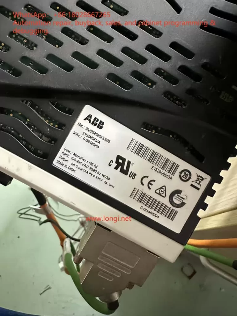
In modern industrial automation, drive safety functions are an indispensable part of system design. In applications where the motor torque must be stopped quickly and reliably, the STO (Safe Torque Off) function plays a crucial role. The ABB MicroFlex e150 servo drive, as a high-performance multi-purpose servo drive, integrates a dual-channel STO safety input circuit that meets international safety standards. Correctly understanding its principle and wiring method is essential not only for the proper operation of the equipment, but also for the safety of personnel and machinery.
This article, based on official documentation and field experience, will analyze in depth the ABB MicroFlex e150’s STO interface design, working principle, and both bench-test and field wiring schemes.
2. Overview of the STO Function
2.1 What is STO?
STO (Safe Torque Off) is a safety function used to immediately cut off the drive pulses to the motor, stopping torque production and preventing unintended motion. Key characteristics:
Fast response – cuts torque without needing mechanical braking
No mechanical wear – electronic action, no brake wear
Safe and reliable – compliant with EN ISO 13849-1 and IEC 61800-5-2 safety standards
In the ABB MicroFlex e150, the STO inputs control the IGBT gate drive enable signals for the power output stage. If the drive detects an STO input open, it will instantly remove gate drive signals and shut down the motor torque.
2.2 Dual-channel redundancy design
The MicroFlex e150 uses a dual-channel STO system:
STO1: X3:18 (positive) and X3:8 (SREF reference)
STO2: X3:19 (positive) and X3:9 (SREF reference)
The two channels are fully independent. If either channel is open, the drive enters the STO state. This redundancy improves fault tolerance and allows higher safety integrity levels.
3. Hardware structure and principle
3.1 Interface layout
According to the ABB hardware manual, the X3 connector is a multifunction digital I/O interface. Relevant pins for STO are:
Pin 18 (STO1 +) – channel 1 positive
Pin 8 (SREF) – channel 1 reference
Pin 19 (STO2 +) – channel 2 positive
Pin 9 (SREF) – channel 2 reference
The drive’s control power input is located on the X2 connector (+24 V and 0 V). This same supply also powers the STO input circuits.
3.2 Internal circuit principle
From the manual’s schematic, each STO input includes:
A 33 Ω series resistor (current limiting)
A 6.8 kΩ resistor (biasing)
An optocoupler (TLP281) for isolation
Connection to the internal drive ground
When an external 24 V DC is applied between STO+ and SREF, the optocoupler turns on, the channel is detected as “closed,” and the drive is allowed to enable the motor output. If no voltage is present, the drive disables torque output.
4. E10033 fault cause and clearing method
4.1 Cause of the fault
In the manual, E10033 is defined as “Safe Torque Off input active” – in other words, at least one STO channel is open. Typical causes:
STO inputs not wired (common during bench testing)
Only one channel wired; the other left floating
Safety relay or external safety circuit is open
Wiring error; SREF not properly connected to control 0 V
4.2 Temporary test wiring
For bench testing or lab environments without a safety circuit, the fault can be cleared by temporary jumpers:
From X2:+24 V, take two wires to X3:18 (STO1+) and X3:19 (STO2+)
From X2:0 V, take two wires to X3:8 (SREF) and X3:9 (SREF)
Both channels now receive 24 V relative to SREF, so the drive sees STO closed
Power up – the E10033 fault disappears and the drive can be enabled
⚠ This is for testing only. In production systems, a proper safety device must be used.
5. Safety wiring in engineering applications
In real installations, the STO channels should be driven by safety-certified control devices such as:
Dual-channel safety relays (e.g., Pilz PNOZ)
Safety PLCs (e.g., ABB Pluto, Siemens S7-1500F)
Emergency stop button + safety relay combinations
5.1 Wiring essentials
Two independent channels – STO1 and STO2 each controlled by separate contacts of a safety relay
Common reference – SREF pins must be connected to the control power 0 V
Shielding & EMC – use twisted shielded pairs for STO signals; ground the shield at one end
5.2 Safety level considerations
According to EN ISO 13849-1, combining dual-channel STO with a safety relay can achieve Performance Level e / SIL3 safety integrity. Such a setup is widely used in robotic arms, CNC machines, packaging lines, and other equipment needing quick, safe shutdown.
6. Field commissioning tips
Check STO before first power-on – the drive ships with STO enabled; without wiring, it will always fault E10033.
Monitor STO status in software – Mint WorkBench allows real-time monitoring of STO channel states to diagnose wiring or circuit issues.
Test with an external 24 V – during commissioning, a direct 24 V supply can be used to simulate STO closure for verification.
Avoid overvoltage – STO inputs accept only 24 V DC; applying AC or >30 V DC can damage the optocouplers.
Do not mix SREF connections – each SREF must be tied correctly to its channel; leaving them floating or mismatched can cause faults.
7. Conclusion
The ABB MicroFlex e150’s STO interface is designed to meet high safety requirements. Dual-channel redundancy ensures that the motor torque can be safely and quickly disabled in critical situations. Whether in a bench test or in a full-scale installation, understanding the STO principle and wiring method is the foundation for both reliable operation and safety compliance.
Key takeaways:
Both STO channels must be closed to enable the drive
Bench testing can use temporary jumpers, but production must use a compliant safety circuit
Proper wiring, shielding, and grounding are vital to avoid nuisance trips
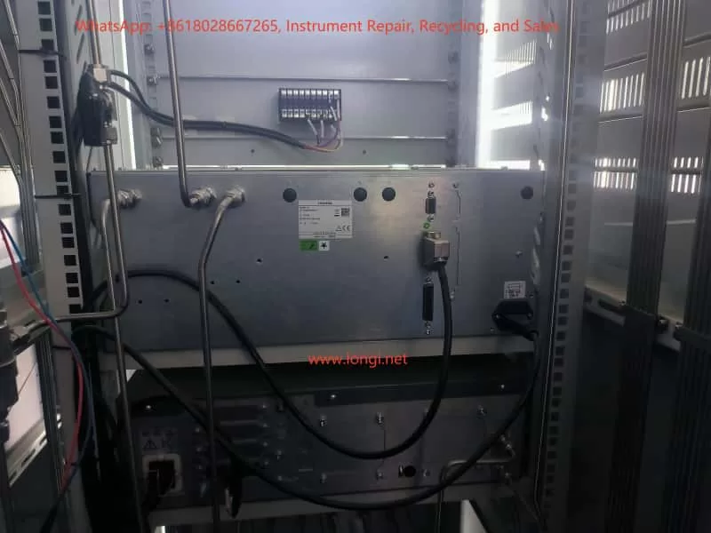
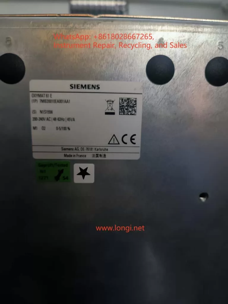
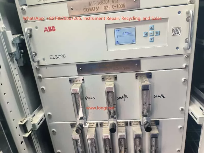
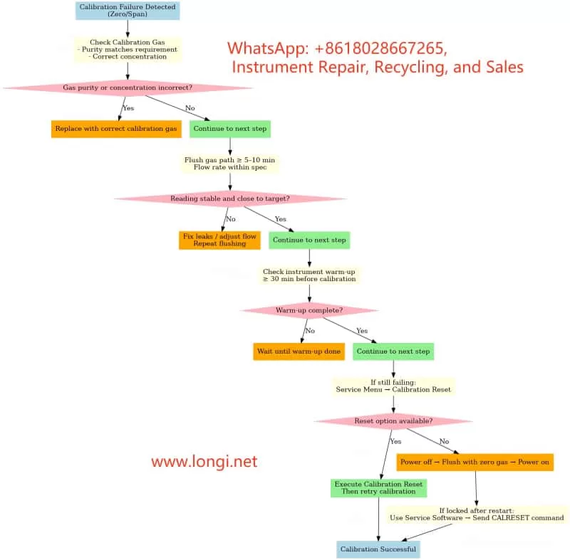
The ABB EL3020 (equipped with the Uras26 infrared module) is a high-precision, multi-component gas analyzer widely used in chemical, metallurgy, power, and environmental sectors for continuous CO₂, CO, CH₄, and other gas measurements. To ensure measurement accuracy and long-term stability, Zero Point Calibration and Span Calibration must be performed regularly. However, during field calibration, engineers often encounter “Calibration Rejected,” “Half Span Shift,” or complete lockout after a failed attempt, preventing further calibration and impacting operation.
This article explains the calibration principle, common causes of failure, error phenomena, troubleshooting steps, and recovery methods. It is based on real field cases, providing engineers with actionable, field-ready solutions.
2. Calibration Principles of the EL3020 (Uras26)
2.1 Zero Point Calibration
The purpose of zero point calibration is to eliminate background interference signals from the optical system and sensors when no target gas is present, aligning the measurement curve to zero.
Condition: Introduce zero gas without the target component (e.g., high-purity nitrogen or zero air).
Requirement: Gas purity must be adequate (CO₂ < 0.1 ppm for a 0–5 ppm range), the sampling path fully flushed, and readings stable.
2.2 Span Calibration
Span calibration adjusts the analyzer’s sensitivity near the full scale so that the measured value matches the standard gas concentration.
Condition: Introduce certified calibration gas with a known concentration (e.g., 3 ppm CO₂).
Requirement: Gas concentration must be accurate and stable, and match the value configured in the analyzer.
2.3 Calibration Protection Mechanism
To prevent operator errors from causing measurement drift:
If the current reading deviates too far from the expected zero/span value, the analyzer will display a “Span Shift” or “Half Span Error” warning.
In some firmware versions, a failed calibration triggers an automatic calibration lock, requiring reset/unlock before retrying.
3. Common Calibration Issues and Root Causes
3.1 “Half Span Error” Warning
Causes:
Incorrect calibration gas concentration (zero gas contains CO₂ or span gas concentration mismatch).
Residual sample gas in the line or insufficient flushing time.
Abnormal flow rate (too low/high or unstable).
Analyzer not stabilized (insufficient warm-up or optical drift).
Recommendations:
Verify calibration gas concentration and label match.
Flush for ≥5–10 minutes before calibration.
Adjust flow rate to recommended value (e.g., 60 L/h).
Warm up for ≥30 minutes before calibration.
3.2 Zero Calibration Rejection
Causes:
Current reading outside acceptable zero range (e.g., <0.1 ppm for a 0–5 ppm range).
Calibration lock active after a failed attempt.
Menu access restricted (requires service password).
Recommendations:
Confirm zero gas purity (CO₂ < 0.1 ppm).
Extend flushing until reading stabilizes.
Check service menu for Calibration Reset option.
If locked, perform unlock/reset before retrying.
3.3 Lockout After One Failed Calibration
Causes:
Firmware protection: Logs the failure and blocks further calibration until cleared.
Data integrity protection: Prevents repeated incorrect calibrations from accumulating drift.
Unlock Methods:
Menu Reset: Service → Calibration Reset.
Power cycle + Zero gas flush.
Factory Calibration Restore (use with caution – overwrites all current calibration data).
Serial Command Unlock via ABB EL3020 Service Tool (CALRESET command).
4. Field Troubleshooting and Operating Steps
4.1 Pre-Calibration Checklist
Gas Verification
Confirm gas label matches instrument settings.
Use ≥99.999% high-purity nitrogen or equivalent zero gas.
Flow and Gas Path
Check flowmeter reading matches recommended spec.
Inspect for leaks and verify valve positions.
Warm-up and Stability
Warm up for 30–60 minutes.
Flush for 5–10 minutes after switching gases.
4.2 Calibration Execution
Press the wrench icon on the right-hand side of the display to enter Maintenance Menu.
Select Manual Calibration.
Choose Zero Point or Span depending on the operation.
Wait for the reading to stabilize before pressing OK.
Verify reading changes after calibration completes.
4.3 After Calibration Failure
Verify gas source → Flush → Retry.
If still failing → Service Menu → Calibration Reset.
If no reset option → Power cycle with zero gas flushing.
If lock persists → Use service software via serial port to send CALRESET.
5. Case Study: CO₂ Zero Point Calibration Failure
Scenario:
Instrument: ABB EL3020 (0–5 ppm CO₂ range).
Zero gas: 99.999% high-purity nitrogen.
Flow rate: 60 L/h.
Issue: Zero point calibration triggers “Half Span Error,” lockout after failure.
Investigation:
Gas purity verified.
Found flushing time was only 2 minutes – insufficient for stability.
Extended flushing to 10 minutes → Reading dropped from 0.35 ppm to 0.05 ppm.
Performed Calibration Reset → Zero point calibration succeeded.
Takeaway:
Insufficient flushing time is a common cause.
First step after failure: reset/unlock before retry.
6. Button & Icon Functions
Left Icon (Envelope/File) Data logging and viewing functions. Opens historical records and calibration logs.
Right Icon (Wrench) Maintenance and calibration access: zero point, span calibration, gas path test, sensor status.
7. Preventive Maintenance Tips
Regularly verify calibration gas purity to avoid contamination.
Flush sampling lines thoroughly before calibration.
Perform zero and span calibration according to manufacturer’s recommended cycle.
Train operators to follow correct calibration procedures to minimize errors.
8. Conclusion
The ABB EL3020 (Uras26) offers stable, reliable high-precision gas analysis when paired with proper gas path management and calibration. Understanding the calibration principle, protection mechanism, and common failure modes enables operators to troubleshoot effectively and reduce downtime. When calibration fails or lockout occurs, follow the outlined troubleshooting steps—starting from gas source and flow checks to warm-up, flushing, and finally reset/unlock procedures—to quickly restore normal operation.