The Shihlin SE2 series frequency inverter is a high-performance device widely used in various industrial control systems. This article provides a detailed user guide for the Shihlin SE2 series frequency inverter, including an introduction to the operating panel functions, parameter settings, external terminal control, fault codes, and their resolution methods.
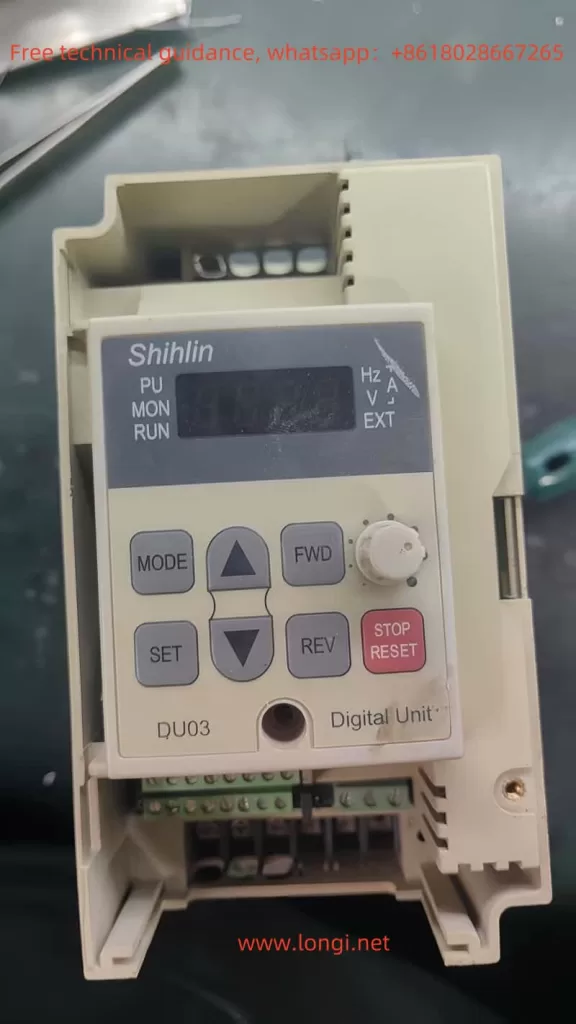
Introduction to Operating Panel Functions
Password Setting and Removal
The Shihlin SE2 series frequency inverter offers password protection to prevent unauthorized operation. The following are the steps to set and remove the password:
- Setting the Password:
- Enter the parameter setting mode and locate the password setting option (usually P.294 and P.295).
- Input the desired password and save the settings.
- Removing the Password:
- Enter the parameter setting mode and locate the password setting option.
- Set the password to the default value (usually 0000) and save the settings.
Parameter Access Restriction
To prevent unauthorized parameter modifications, you can set parameter access restrictions:
- Setting Parameter Access Restrictions:
- Enter the parameter setting mode and locate the parameter access restriction option (usually P.77).
- Set the parameter access restriction to “Read-only” or “Access Denied” and save the settings.
Parameter Initialization
In some cases, you may need to reset all parameters to their factory settings. The following are the steps for parameter initialization:
- Parameter Initialization:
- Enter the parameter setting mode and locate the parameter initialization option (usually P.998).
- Select “Restore Factory Settings” and save the settings.
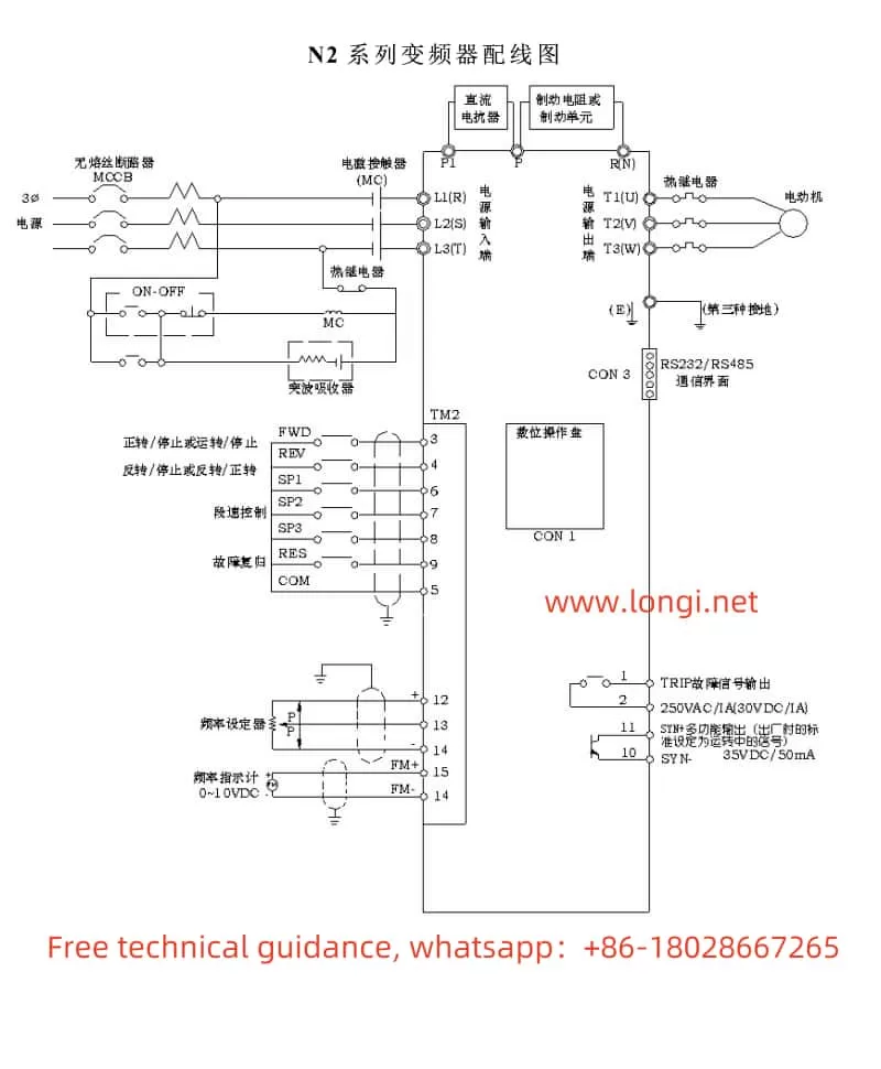
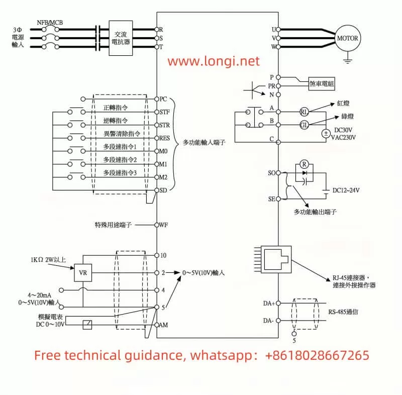
External Terminal Forward/Reverse Start/Stop and External Potentiometer Speed Control
The Shihlin SE2 series supports forward/reverse start/stop and speed control via an external potentiometer. The following are the specific setup steps and wiring methods:
External Terminal Forward/Reverse Start/Stop
- Setting Parameters:
- Enter the parameter setting mode and locate the operation mode selection parameter (usually P.79).
- Set the operation mode to “External Mode” (usually P.79=2).
- Set the start terminal function (usually P.78) and select the external forward/reverse terminal.
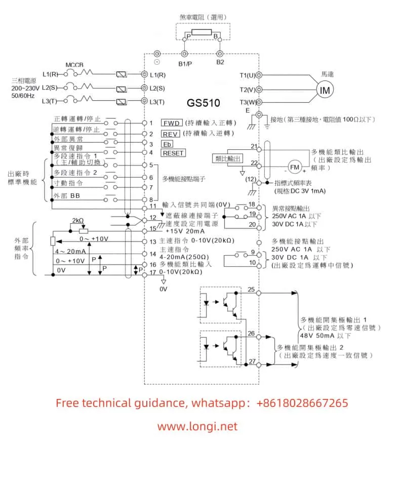
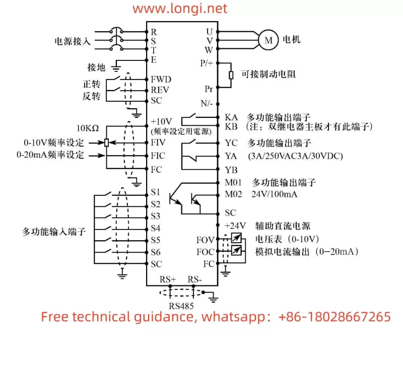
- Wiring:
- Connect the external start terminal (STF) and stop terminal (STR) to the corresponding terminals on the inverter.
External Potentiometer Speed Control
- Setting Parameters:
- Enter the parameter setting mode and locate the operation mode selection parameter (usually P.79).
- Set the operation mode to “External Mode” (usually P.79=2).
- Set the target frequency source to external voltage/current signal (usually P.39).
- Wiring:
- Connect the output terminal of the external potentiometer to the 4-5 terminal of the inverter.
Fault Codes and Their Resolution
The Shihlin SE2 series provides a detailed list of fault codes to help users quickly identify and resolve issues. The following are some common fault codes, their meanings, and resolution methods:
Common Fault Codes
- Overcurrent Fault (OC0):
- Meaning: The inverter detects a current exceeding the set value.
- Resolution: Check if the motor and load are normal, and ensure the motor is not operating under overload.
- Overvoltage Fault (OV0):
- Meaning: The inverter detects a voltage exceeding the set value.
- Resolution: Check if the power supply voltage is stable, and ensure the power supply voltage is within the allowed range.
- Overheating Fault (OT0):
- Meaning: The internal temperature of the inverter exceeds the set value.
- Resolution: Check the heat dissipation of the inverter, ensure good ventilation, and add heat dissipation measures if necessary.
- Communication Fault (CM0):
- Meaning: There is a communication anomaly between the inverter and the upper computer.
- Resolution: Check if the communication cables are correctly connected, and ensure the communication parameters are set correctly.
- Earth Fault (ERR):
- Meaning: The inverter detects an earth fault.
- Resolution: Check the grounding of the inverter and ensure it is properly grounded.
- Phase Loss Fault (PHL):
- Meaning: The inverter detects a phase loss in the power supply.
- Resolution: Check the power supply for any phase loss and ensure all phases are properly connected.
Fault Resolution Steps
- Confirm the Fault Code:
- View the fault code on the inverter’s display to determine the type of fault.
- Consult the User Manual:
- Look up the fault code in the user manual to find the corresponding fault description and resolution method.
- Execute the Resolution Method:
- Follow the instructions in the user manual to resolve the fault and restore the inverter to normal operation.
Conclusion
The Shihlin SE2 series user manual provides detailed operating instructions and fault resolution methods to help users quickly get started and resolve issues during operation. By correctly setting passwords, parameter access restrictions, parameter initialization, external terminal control, and handling fault codes, users can efficiently use and maintain Shihlin SE2 series products. This article aims to provide valuable references to help users better utilize Shihlin SE2 series products.