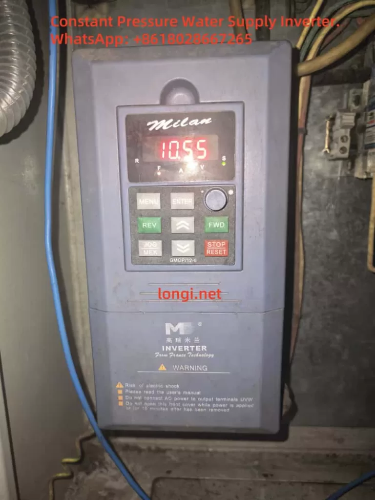
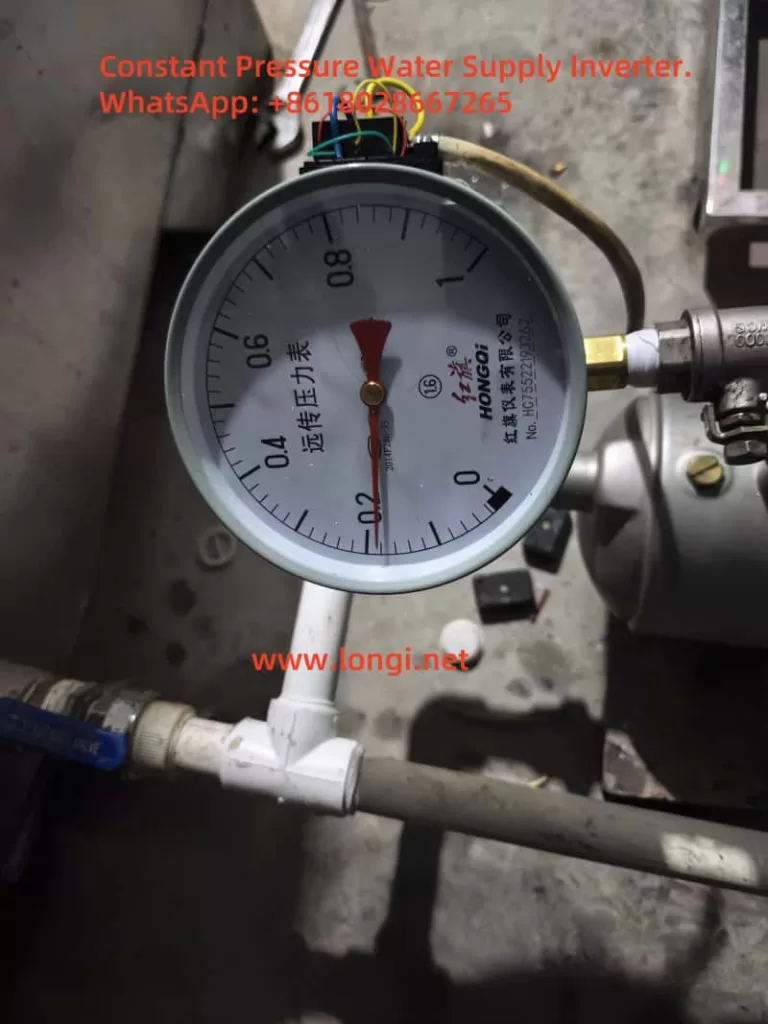
Constant pressure water supply technology is widely used in modern industrial and civil water systems for efficient and energy-saving operation. This project uses the Milan M5000 inverter as the control core, combined with the YTZ-150 potentiometric remote pressure gauge, to construct a closed-loop constant pressure control system. It enables automatic adjustment of a single water pump to ensure the outlet pressure remains stable within the set range.
The system features low cost, easy maintenance, and fast response, making it suitable for small water supply systems, factory cooling water circulation, boiler water replenishment, and more.
2. Main Hardware and Functional Modules
1. Inverter: Milan M5000 Series
Built-in PID controller
Supports multiple analog inputs (0-10V, 0-5V, 4-20mA)
Provides +10V power output terminal for sensor power supply
Rated working voltage ≤6V, but 10VDC tested in practice with stable long-term operation
Outputs a voltage signal (typically 0–5V) varying with pressure via a voltage divider principle
3. Control Objective
Adjust pump speed using the inverter to maintain constant pipe pressure
Increase frequency when pressure drops, and decrease when pressure exceeds the setpoint to save energy
3. Wiring and Jumper Settings
1. 3-Wire Sensor Wiring (Tested with 10V)
Sensor Wire
Function
Inverter Terminal
Red
+10V supply
Connect to +10V
Green
Ground (GND)
Connect to GND
Yellow
Signal output
Connect to VC1 input
2. Analog Input Jumper JP8
Default: 1–2 connected, indicating 0–10V input
Keep the default setting in this project (no need to switch to 2–3)
4. PID Parameter Settings (Based on Field Use)
Parameter
Description
Value
Note
P7.00
Enable closed-loop control
1
Enable PID control
P7.01
Setpoint source
0
Digital input from panel
P7.02
Feedback source
0
VC1 analog input (0–10V)
P7.05
Target pressure value (%)
30.0
Corresponds to 0.3MPa if P7.24=1.000
P7.07
Feedback gain
1.00
Linear scaling factor for feedback
P7.10
PID control structure
1
Proportional + integral control
P7.11
Proportional gain
0.50
Recommended initial value
P7.12
Integral time constant
10.0
In seconds
P7.24
Pressure sensor range (MPa)
1.000
1.000 MPa full-scale
P1.19
Maximum voltage input
5.00
Matched to 0–5V signal range
5. Sleep Function Configuration
To enable energy saving when there is no pressure demand, the inverter can be configured to sleep:
Parameter
Description
Value
Note
P7.19
Wake-up threshold
0.001
Minimum pressure to resume operation (MPa)
P7.20
Sleep threshold
1.000
Enter sleep mode above this value (MPa)
P7.23
Constant pressure mode
1
One-pump control mode
6. PID Tuning Guidelines
After starting the system, observe pressure fluctuations:
If large oscillations, reduce P7.11 (proportional gain)
If sluggish response, reduce P7.12 (integral time)
Aim to maintain output pressure within ±2% of the P7.05 set value
Ensure return pipes have damping to prevent sudden pressure spikes
7. Key Considerations
Keep JP8 jumper at default 1–2 for 0–10V input
YTZ-150 sensor has been tested with 10V power supply and works stably
Ensure proper grounding (PE terminal) to avoid PID interference from common-mode noise
If feedback signal is noisy, add a filter capacitor (0.1–0.47μF) between VC1 and GND
8. Conclusion
With this design, the Milan M5000 inverter combined with the YTZ-150 pressure sensor delivers a cost-effective and reliable constant pressure control solution for water systems. The inverter’s built-in PID control simplifies implementation compared to external PLCs and offers strong performance with minimal tuning. As long as power supply, signal matching, and grounding are properly managed, the system achieves excellent closed-loop control stability.
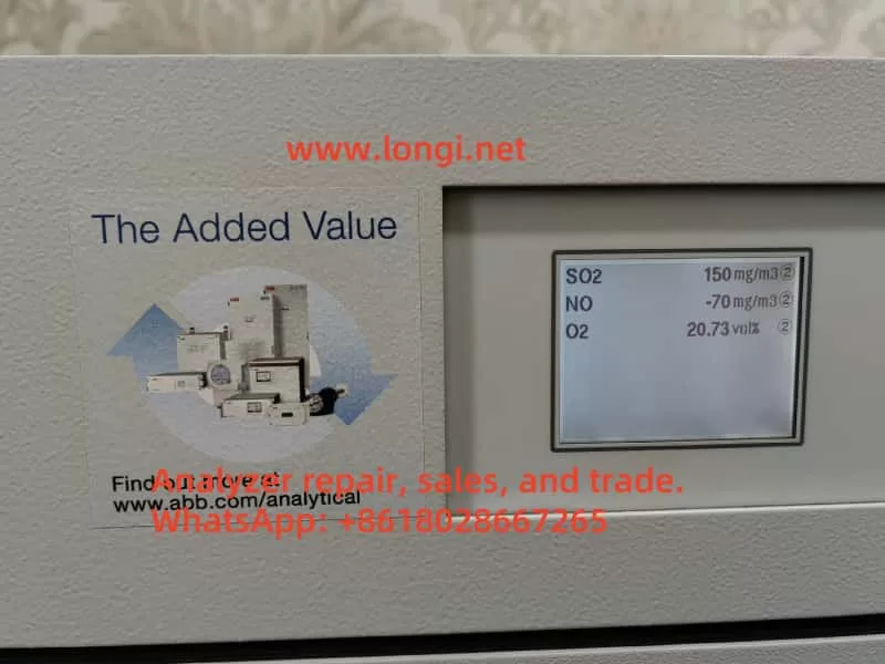
Powerful Functionality: The ABB EL3020 is a high-precision continuous gas analyzer supporting multiple modules (e.g., Uras26, Magnos206) for industrial gas monitoring.
Wide Applications: Primarily used in non-hazardous environments for measuring flammable gases, suitable for industrial process control and environmental monitoring.
Operational Caution: Must be operated by qualified personnel, adhering to strict safety and installation requirements to prevent leaks or equipment damage.
Maintenance and Troubleshooting: Regular calibration and seal integrity checks are critical; fault codes provide clear diagnostics for timely resolution.
User-Friendly Design: Features an intuitive display interface and multiple connectivity options, supporting remote configuration and data logging.
This guide, based on the ABB EL3020 user manual, aims to assist users in understanding its features, usage, precautions, and maintenance procedures.
Features and Capabilities
The ABB EL3020 is a continuous gas analyzer designed for industrial applications, capable of accurately measuring the concentration of individual components in gases or vapors. Part of the ABB EasyLine series, it combines advanced technology with user-friendly design, making it suitable for various industrial settings.
Key Features
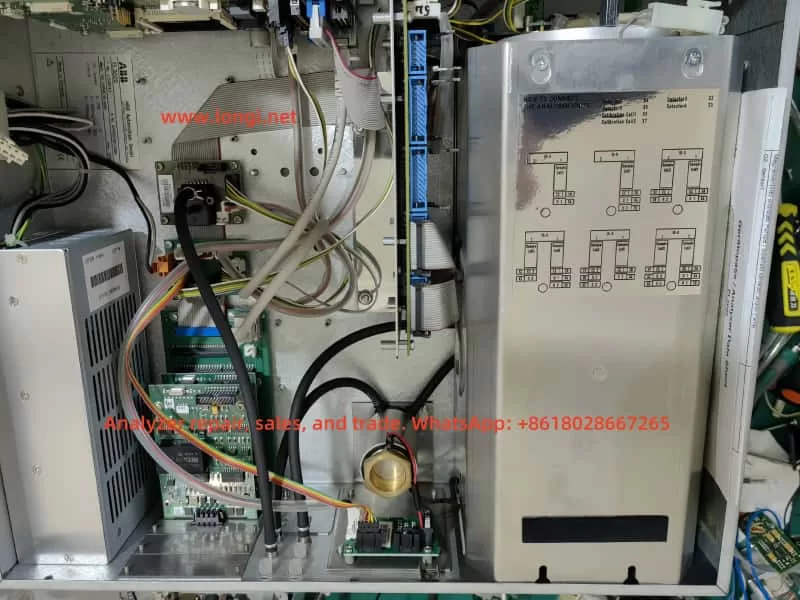
Versatile Analyzer Modules: Supports Uras26 (infrared), Magnos206 (oxygen), Caldos27 (thermal conductivity), Limas23 (ultraviolet), and ZO23 (zirconia) modules, enabling measurement of gases like CO, CO₂, CH₄, and O₂.
Robust Design: Housed in a 19-inch rack-mounted enclosure with IP20 protection, weighing 7-15 kg, ideal for indoor industrial environments.
Flexible Connectivity: Supports 100-240 V AC power, digital I/O, analog outputs, Modbus, Profibus, and Ethernet interfaces for seamless system integration and remote operation.
Calibration Options: Offers automatic and manual calibration using nitrogen, air, or span gases, configurable via the device or software (e.g., ECT).
Intuitive Interface: Displays gas component names, measured values, and units in measurement mode; menu mode provides configuration and maintenance functions with password protection and a 5-minute timeout.
Data Communication: Connects to computers via Ethernet using TCT-light and ECT software for configuration, calibration, and data logging, supporting Modbus TCP/IP protocol.
Applications and Usage Precautions
Applications
The ABB EL3020 is designed for measuring flammable gases in non-hazardous environments, with applications including:
Industrial Process Control: Monitors gas concentrations in production processes to ensure stability.
Environmental Monitoring: Measures industrial emissions to comply with regulatory standards.
Energy Sector: Used in power plants for gas analysis to enhance efficiency and safety.
Chemical Industry: Monitors gas components in chemical reactions to ensure safety and quality.
The device is suitable for indoor environments below 2000 meters altitude, with flammable gas concentrations not exceeding 15 vol.% CH₄ or C1 equivalents. It is not suitable for ignitable gas/air or gas/oxygen mixtures or corrosive gases without proper preprocessing.
Usage Precautions
To ensure safety and performance, adhere to the following precautions:
Personnel Requirements: Only qualified personnel familiar with similar equipment should operate or maintain the device.
Safety Compliance: Follow national electrical and gas-handling safety regulations, ensure proper grounding, and avoid using damaged or transport-stressed equipment.
Installation Environment: Install in a stable, well-ventilated location away from extreme temperatures, dust, and vibrations. For flammable gas measurements, ensure adequate air circulation (minimum 3 cm clearance), and if installed in a closed cabinet, provide at least one air change per hour.
Gas Handling: Use stainless steel or PTFE gas lines, avoid opening combustion gas paths, and regularly check seal integrity to prevent leaks that could cause fires or explosions. Limit combustion gas flow (e.g., max 10 l/h H₂ or 25 l/h H₂/He mixture) and install a shut-off valve in the gas supply line.
Environmental Protection: Protect the device from mechanical damage or UV radiation, especially the display window.
Usage Restrictions: The oxygen sensor and integrated gas feed option must not be used for flammable gas measurements.
Detailed Usage Steps and Methods
Preparation
Before installing the EL3020, ensure:
Thorough review of the manual to understand application and safety requirements.
Preparation of necessary materials, such as gas lines, fittings, and power cables.
Verification that the installation site meets environmental requirements (stable, ventilated, no extreme temperatures).
Unpacking and Installation
Unpacking: Due to the device’s weight (7-15 kg), two people are recommended for unpacking.
Gas Connections: Use PTFE sealing tape to connect sample, process, and test gas lines, ensuring a tight seal.
Installation: Secure the 19-inch enclosure in a cabinet or rack using appropriate mounting rails.
Connections
Gas Lines: Connect sample, process, and test gas lines, ensuring cleanliness and secure sealing. Install a micro-porous filter and flowmeter for protection if needed.
Electrical Connections: Connect power (100-240 V AC), digital I/O, analog outputs, and communication interfaces (Modbus, Profibus, Ethernet) as per the manual’s wiring diagrams.
Startup
Power On: Connect and turn on the power supply.
Purging: Purge the sample gas path with an inert gas (e.g., nitrogen) for at least 20 seconds (100 l/h) or 1 hour (200 l/h) to clear residual gases.
Warm-Up: Allow 0.5-2 hours for warm-up, depending on the analyzer module.
Introduce Sample Gas: After warm-up, introduce the sample gas.
Configuration and Calibration: Verify configuration settings and perform calibration if necessary, using test gases (e.g., nitrogen) to adjust zero and span points.
Operation
Measurement Mode: The display shows gas component names, measured values, and units for routine monitoring.
Menu Mode: Access configuration, calibration, or maintenance functions via the menu, requiring a password. The system auto-exits after 5 minutes of inactivity.
Calibration Methods: Perform automatic calibration (using preset test gases) or manual calibration (via menu or ECT software to adjust setpoints).
Data Logging: Use TCT-light or ECT software via Ethernet for data recording, compliant with QAL3 requirements.
Remote Monitoring: Integrate with monitoring systems via Modbus TCP/IP protocol.
Routine Maintenance and Fault Code Meanings
Routine Maintenance
To ensure long-term performance, conduct regular maintenance:
Seal Integrity Checks: Use pressure tests or leak detectors to regularly verify the integrity of sample and combustion gas paths, ensuring a leak rate < 1×10⁻⁴ hPa l/s for combustion gas and < 2×10⁻⁴ hPa l/s for sample gas.
Calibration: Perform automatic or manual calibration as needed, using specific test gases (e.g., nitrogen) to adjust setpoints and ensure measurement accuracy.
Visual Inspection: Regularly check for wear, damage, or contamination, particularly in gas lines, fittings, and the display.
Software Updates: Periodically update ECT and other software to ensure compatibility and functionality.
Fault Codes
The EL3020 provides status messages (codes 110 to 803), categorized as follows:
A: Failure
W: Maintenance Request
F: Maintenance Mode
S: Overall Status
Common fault codes and their handling methods are listed below:
Code
Category
Meaning
Handling Method
110
A S a
Instrument is booting
No action required, informational
122
A S a
IO module defective
Replace IO module
250
A S a
Analyzer not found
Check connectors and cables
301
A S a
Measured value exceeds A/D converter range
Check sample gas concentration and connectors, contact service if needed
322
A S a
Flame is out
Check gas supply and heater plug (for flame-based modules)
412
F S a
Ignition failed
Manually restart via menu, check process gases
Maintenance Procedures
Identify Fault: Access fault codes via the menu.
Troubleshooting: Follow the manual’s instructions for each fault code. For example:
Code 322 (Flame Out): Check combustion gas supply and heater plug.
Code 250 (Analyzer Not Found): Inspect cables and connectors.
Contact Service: If the issue persists, contact ABB Service; avoid attempting repairs beyond your qualifications.
Conclusion
The ABB EL3020 Continuous Gas Analyzer is a robust and versatile tool for industrial gas monitoring, offering high precision and flexibility across various applications. By following the usage steps, precautions, and maintenance procedures outlined in this guide, users can ensure safe operation and sustained performance. Regular calibration, seal integrity checks, and prompt resolution of fault codes are essential for maintaining measurement accuracy and safety.
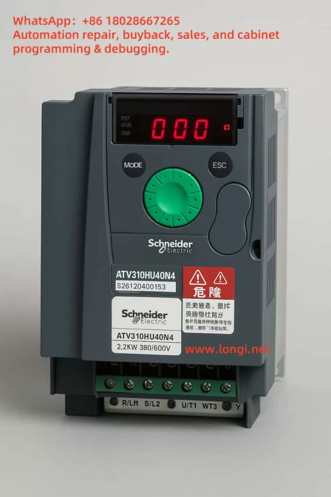
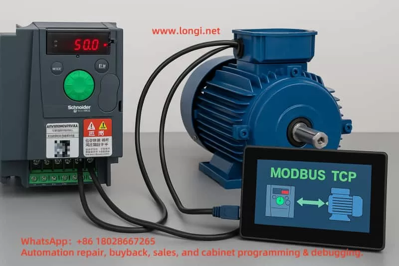
This project aims to build a control network without using a PLC by directly connecting 9 Schneider Altivar-310 series variable frequency drives (VFDs) to a human-machine interface (HMI) through the Modbus TCP protocol. The HMI serves as the sole Modbus master, and all VFDs function as slave devices, enabling direct command transmission, status monitoring, and parameter interaction.
This architecture is especially suitable for small to medium automation systems, reducing hardware costs, simplifying the control structure, and improving debugging efficiency.
2. Hardware Checklist
Item
Function
Notes
Altivar 310 + VW3A3616 module × 9
Ethernet interface for each VFD
Install securely into the communication option slot
Industrial Ethernet switch (≥10 ports, 100 Mbps is fine)
Star topology backbone
DIN-rail mount, industrial-grade recommended
Shielded CAT5E/6 Ethernet cables
Noise-resistant communication
Keep under 100 meters; ground shield at one end
HMI panel supporting Modbus TCP
Acts as the master device
Weintek, Schneider Magelis, and similar brands recommended
24V DC power supply (if required by HMI)
Auxiliary power source
All devices should share the same PE grounding system
3. Recommended IP and Modbus Address Allocation
VFD No.
Static IP
Subnet Mask
Modbus Slave ID
1
192.168.0.11
255.255.255.0
1
2
192.168.0.12
255.255.255.0
2
…
…
…
…
9
192.168.0.19
255.255.255.0
9
Tip: Assign the HMI an address like 192.168.0.10. If used in an isolated system, the gateway can be set to 0.0.0.0.
4. Configuring IP Address for Each VFD Using SoMove
Connect the PC to the VFD via Ethernet cable and set the PC’s IP address to the same subnet (e.g., 192.168.0.100).
Launch the SoMove software, select Modbus TCP as the communication type, and enter the target VFD’s IP address (default or temporary), with Modbus slave address set to 1.
In the Communication → Ethernet menu:
Set IP Mode to Manual
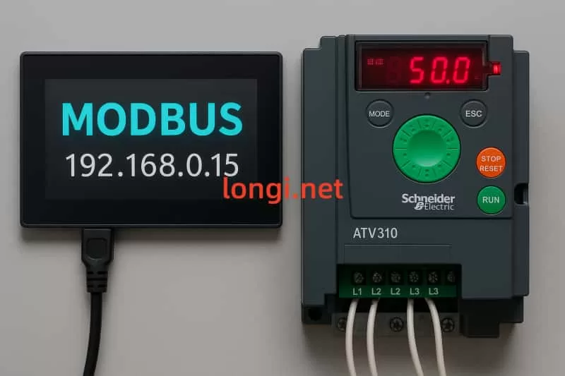
Enter a unique static IP for each VFD (e.g., 192.168.0.15)
Set subnet mask to 255.255.255.0
Set gateway to 0.0.0.0 or as required by your network
Set protocol to Modbus TCP (value = 0)
Set Modbus slave address from 1 to 9
Save the parameters and reboot the VFD to apply the new IP.
Repeat this process for all 9 drives, assigning unique IPs and Modbus IDs.
5. HMI Modbus Register Mapping Example
Function
Register Address (Offset)
Data Type
Scaling
Command word (Run/Stop, Direction)
0
16-bit
Bit-level
Frequency setpoint (Hz)
1
16-bit
0.1 Hz per bit
Output frequency feedback
102
16-bit
0.1 Hz per bit
Drive status word
128
16-bit
Bit-level
Fault code
129
16-bit
Integer
Note: The ATV310’s Modbus register map starts at 40001. Some HMI brands use “offset 0”, so register 1 corresponds to 40001.
6. Network Topology and Installation Practices
Star Topology: Connect all 9 VFDs and the HMI to a central switch.
EMC Wiring Practices:
Separate power and Ethernet cable routing to minimize interference
Bond all VFDs and the switch ground terminals to the control cabinet’s PE bar
Labeling and Documentation:
Clearly label each Ethernet cable with corresponding VFD number and IP
Place a printed network topology diagram inside the control cabinet
7. Commissioning Procedure
Ping Test: Use a PC to ping each VFD’s IP address to verify communication.
HMI Communication Test:
Create a template screen for one VFD
Copy it for other VFDs, changing only the IP and Modbus ID
Test frequency control, start/stop, and feedback display for each unit
Stress Test: Run rapid start/stop cycles and observe response consistency and screen refresh speed (<200 ms is ideal).
Project Backup: Save each VFD’s .stm file from SoMove and the full HMI project into a version-controlled system.
8. Performance & Limitations
Aspect
Details
Max refresh speed
Reading 10 registers per drive takes ~20–40 ms; 9 drives ≈ 200–400 ms total
Real-time behavior
Suitable for monitoring and basic control; not ideal for high-speed interlocks (<20 ms)
Redundancy
A single switch failure disconnects all; consider dual-ring switches for critical uptime
Security
Use VLANs or restrict switch ports to specific MACs to prevent unauthorized connections
9. Maintenance and Optimization Tips
Always backup SoMove configuration files after parameter changes
Stick Modbus slave ID labels onto each VFD’s front panel
Lock HMI screens with password protection to prevent accidental changes
Annually inspect Ethernet switch ports; replace the unit if CRC errors or dust buildup is found
10. Conclusion
By installing VW3A3616 modules and configuring individual IP addresses and Modbus IDs for each ATV310, a clean star-topology network can be built for direct HMI communication. This setup simplifies wiring, eliminates the need for a PLC, and significantly reduces costs. It is particularly suitable for small to medium-sized automation projects that require easy maintenance and flexible deployment.
Ethernet Module Installation: The ATV310 VFD does not include a built-in Ethernet port. To enable Modbus TCP over Ethernet, install an optional communication module such as the VW3A3616, which provides an RJ45 interface. Ensure the module is properly mounted and securely inserted into the option slot on the drive.
Connecting the Network: Connect the VFD’s Ethernet port directly to your PC using a standard Ethernet cable, or connect both to the same switch. Configure your PC’s Ethernet interface to be in the same subnet—for example, assign it an IP like 192.168.0.10 with subnet mask 255.255.255.0. Disable firewalls to avoid communication issues.
Initial IP Setup via HMI Panel: If this is the first time using the Ethernet module, its IP address may default to 0.0.0.0, awaiting DHCP. Since you are using static IPs, enter the ATV310’s local HMI panel, navigate to the “Communication (COM-)” → “Ethernet (EtH-)” menu, set IP Mode to “Manual”, and configure a temporary IP (e.g., 192.168.0.15) with the appropriate subnet mask. If there’s no router, set the gateway to 0.0.0.0. After setting, power cycle the VFD to apply the changes.
(2) Connecting to the ATV310 in SoMove
Launch SoMove: Ensure the SoMove software is installed along with the DTM driver package compatible with the ATV310 (usually compatible with ATV31/ATV312 profiles). Open SoMove and start a new project or open an existing one.
Set Up Communication:
Click “Edit Connection/Scan” and choose Modbus TCP as the connection type.
Click the advanced settings (gear icon), then under the “Scan” tab, choose Single Device, enter the temporary IP (e.g., 192.168.0.15) and slave address (default is 1).
Apply and save the configuration.
Scan and Connect: From the main screen, click “Scan”. If the IP and settings are correct, the VFD will be detected. Double-click it to establish the connection and load parameters.
(2) Setting the Static IP Address
Once connected, go to the Communication menu in the device parameter tree, then open the Ethernet (EtH-) submenu. Configure the following:
IP Mode (IpM): Set to Manual (0) to disable DHCP.
IP Address (IPC1–IPC4): Set the 4 bytes individually. For example, to set 192.168.0.15, enter IPC1=192, IPC2=168, IPC3=0, IPC4=15.
Subnet Mask (IPM1–IPM4): Use a typical mask such as 255.255.255.0 (i.e., IPM1=255, IPM2=255, IPM3=255, IPM4=0).
Gateway (IPG1–IPG4): If you’re not using routing, set it to 0.0.0.0.
Ethernet Protocol (EthM): Ensure it is set to 0 for Modbus TCP (not Ethernet/IP).
Parameter Summary:
Parameter Code
Function
Recommended Setting
IpM (IP Mode)
IP acquisition method
0 = Manual (disable DHCP)
IPC1~IPC4
IP address
e.g., 192.168.0.15
IPM1~IPM4
Subnet mask
e.g., 255.255.255.0
IPG1~IPG4
Gateway address
e.g., 192.168.0.1 or 0.0.0.0
EthM (Protocol)
Modbus TCP or Ethernet/IP
0 = Modbus TCP
Once settings are applied, write them to the drive and power cycle the VFD to activate the new static IP address.
(4) Verifying the Configuration
Ping Test: From your PC, use the ping command to check if the VFD responds to the new IP address (e.g., ping 192.168.0.15). A successful response confirms network connectivity.
Reconnect in SoMove: Update the connection settings in SoMove with the new static IP and reconnect. You should be able to scan, access parameters, and monitor status.
Check Ethernet Module LEDs: A solid green light typically indicates normal status. Blinking or red lights may indicate wiring errors, IP conflicts, or module faults.
Modbus Communication Test: If integrating with an HMI or master software, send basic Modbus commands (e.g., reading frequency or writing speed setpoints) to ensure the VFD communicates correctly over Modbus TCP.
Conclusion
By following the above procedure, each ATV310 VFD can be configured with a unique static IP and operate reliably over an Ethernet network using Modbus TCP. This setup is especially effective in systems where communication is directly between an HMI and multiple drives, eliminating the need for a PLC. Proper IP planning, secure connections, and careful testing will ensure a stable and responsive network.
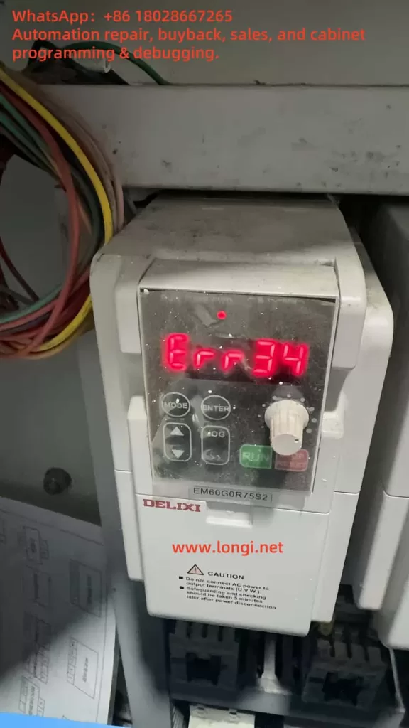
The Delixi EM60 series inverter is a robust variable frequency drive (VFD) designed to regulate the speed and torque of AC motors in industrial applications. Engineered for reliability, it features advanced protective mechanisms to safeguard both the inverter and the connected motor. One such protection is the “quick current limit,” which prevents damage from sudden overcurrent conditions. However, when this limit is exceeded for too long, the inverter triggers the ERR34 fault code, known as “quick current limit timeout” (快速限流超时). This article explores the meaning of the ERR34 fault, its potential causes, and provides a detailed guide on how to troubleshoot and repair this issue, drawing on the Delixi EM60 series user manual and practical VFD maintenance principles.
What Does ERR34 Mean?
The ERR34 fault code indicates that the inverter’s output current has surpassed the quick current limit threshold for a duration exceeding the specified timeout period. In the Delixi EM60 series, this protective feature is part of the motor control strategy, managed through parameters in the P1 group (pages 31-73 of the user manual). The quick current limit activates during transient overcurrent events—such as sudden load spikes or short circuits—by reducing the output frequency or voltage to stabilize the current. If the current remains high beyond the timeout threshold (typically a few seconds), the inverter halts operation and displays ERR34 to prevent damage.
This fault serves as a critical alert, signaling that the system could not resolve an overcurrent condition within the allotted time. Understanding its implications is key to diagnosing whether the issue lies in the motor, wiring, parameters, or the inverter itself.
Potential Causes of ERR34
Several factors can trigger the ERR34 fault. Based on the manual’s fault diagnosis section (pages 191-199) and general VFD operation, the following are the most likely culprits:
Motor Overload Excessive mechanical load, such as a jammed rotor or heavy machinery, forces the motor to draw more current than the inverter can safely handle, activating the current limit.
Incorrect Parameter Settings Misconfigured settings in the P1 group (motor control parameters, pages 31-73) or P3 group (programmable functions, pages 47-117), such as a low current limit or short timeout period, can cause the fault to trigger prematurely.
Power Supply Instability Voltage fluctuations, harmonics, or transients in the input power can disrupt the inverter’s ability to regulate current, as emphasized in the safety guidelines (pages 6-7).
Wiring Issues Loose connections, damaged cables, or short circuits between the inverter and motor can lead to abnormal current spikes. The manual’s installation section (page 213) highlights the importance of secure wiring.
Motor or Inverter Faults Internal motor issues (e.g., shorted windings) or inverter hardware failures (e.g., damaged IGBT modules or current sensors) can sustain overcurrent conditions.
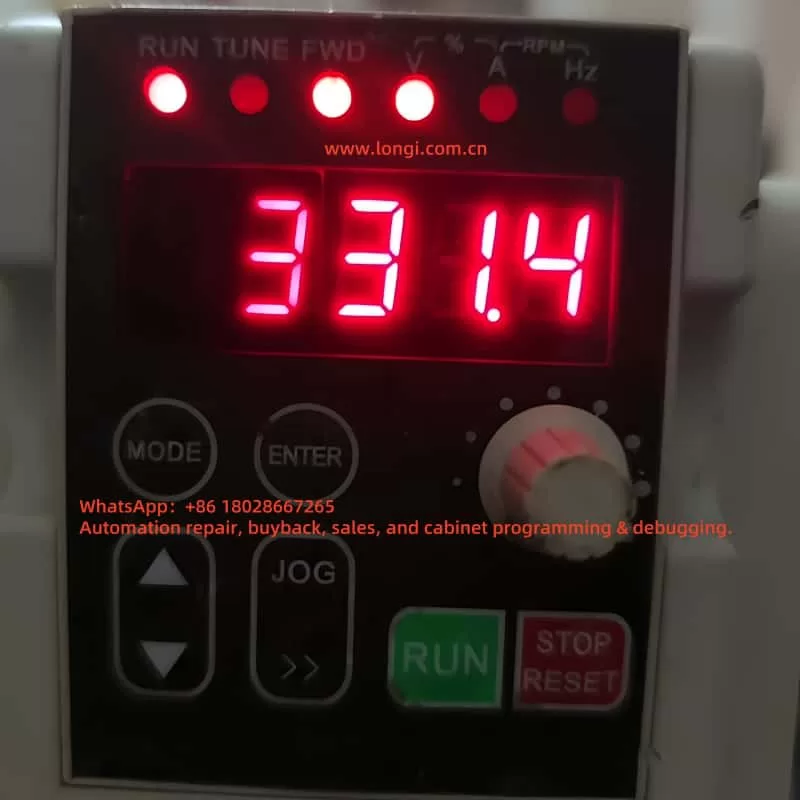
Environmental Factors Dust accumulation or poor ventilation, as observed in the image of an EM60G0R7S2 inverter, can overheat the unit, exacerbating current-related problems.
Troubleshooting the ERR34 Fault
Diagnosing the ERR34 fault requires a systematic approach. The following steps, inspired by the manual’s troubleshooting sections (pages 56-128) and practical experience, will help identify the root cause:
Ensure Safety Disconnect the power supply and verify with a multimeter that the system is de-energized, adhering to the caution label warning against live servicing.
Check Motor Load Inspect the motor and driven equipment for mechanical issues like binding or overloading. Measure the current draw with a clamp meter and compare it to the motor’s rated capacity.
Review Parameter Settings Use the inverter’s keypad (featuring “MODE,” “ENTER,” and arrow buttons) to access the P1 group. Verify the current limit (e.g., P1-03) and acceleration/deceleration times (P1-09, P1-10, page 159). Adjust if they are too restrictive for the application.
Inspect Wiring Examine all connections between the inverter and motor for looseness, fraying, or burn marks. Test for continuity and insulation resistance to rule out shorts.
Assess Power Supply Measure the input voltage to ensure it’s within the specified range (e.g., 380V ± 15% for three-phase models). Use a power quality analyzer to detect noise or surges.
Monitor Environmental Conditions Check the inverter’s surroundings for dust or high temperatures (recommended range: 0-40°C). Clean the unit and ensure proper ventilation.
Reset and Test After addressing potential issues, reset the fault via the “STOP” button or power cycle (page 128). Run the system at a low speed to observe if ERR34 reoccurs.
Solutions and Repairs
Once the cause is pinpointed, apply these solutions:
Reduce Overload Lighten the mechanical load or upgrade to a higher-capacity motor and inverter if the demand exceeds specifications.
Adjust Parameters Increase the current limit or extend the timeout period in the P1 group to accommodate normal operation. For example, lengthening acceleration time (P1-09) can reduce startup current spikes.
Stabilize Power Install a voltage stabilizer or harmonic filter to ensure consistent input power.
Repair Wiring Tighten connections or replace faulty cables, ensuring compliance with the manual’s wiring guidelines (page 213).
Fix Hardware
Motor: Test windings with an insulation tester; repair or replace if defective.
Inverter: If internal components are suspected (e.g., IGBTs), consult Delixi support for repair, as detailed diagnostics may require proprietary tools (P8 group, page 66).
Improve Environment Relocate the inverter to a cleaner, cooler area or add cooling fans to mitigate thermal stress.
Preventive Measures
To avoid future ERR34 faults:
Conduct regular maintenance on the motor and machinery to prevent overloads.
Periodically review P1 and P3 group settings, adjusting for changes in load or application (pages 31-117).
Install surge protectors to safeguard against power issues.
Clean the inverter routinely to remove dust, as recommended in the safety sections (pages 6-7).
Train staff on parameter configuration and fault handling, leveraging the manual’s application cases (pages 180-183).
Conclusion
The ERR34 fault code in the Delixi EM60 series inverter is a vital safeguard against prolonged overcurrent conditions. Whether caused by overload, parameter errors, wiring faults, or environmental factors, this issue can be resolved through careful troubleshooting and targeted repairs. By following the steps outlined and adhering to the user manual’s guidance, users can restore functionality and enhance system reliability. For complex hardware failures, professional assistance from Delixi or a certified technician ensures long-term performance and safety.
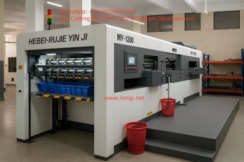
The Fully Automatic Platen Die-Cutting Machine is a specialized device designed for die-cutting and creasing/creasing of flat sheet materials such as cardboard, corrugated paper, and laminated paper. It integrates the traditional “hand press” platen principle with automatic paper feeding, positioning, collecting, fault detection, and safety interlock systems for batch production of color boxes, cartons, wine boxes, labels, hangtags, and some thin plastic packaging products.
I. Device Principle & Process Challenges
1.1 Basic Process of Platen Die-Cutting
Process Flow: Paper Feeding → Positioning → Clamping & Conveying → Die-Cutting/Creasing → Waste Removal → Paper Collecting
Key Features & Challenges:
High Inertia: 320-ton machine requires the crank-link mechanism to decelerate and stabilize near the top dead center.
Tight Timing Coupling Between Stations: Intermittent transport of the gripper bar is synchronized with the die-cutting stroke; any timing deviation risks paper tearing.
Mechanical chain + intermittent cam cause rigid coupling; difficult to optimize speed curves.
Retain mechanical spindle; independent VFD speed control for Feeder. Gripper bar position identified via encoder Z-PULSE to avoid costly electronic cam reconstruction.
Registration & Repeatability
Paper stretching/static electricity, gripper bar spring fatigue.
Front/side guides + photoelectric correction; PLC checks X6/X7 every 10 ms, with high-speed interrupt correction.
Pressure Closed-Loop Control
320-ton hydraulic cylinder pressure drift of 2%.
FX3U-4AD module for 4–20 mA signal; PID regulates Y12 pressure-building valve PWM. Set Press OK = 0.95 × Setpoint.
Safety Category 3
Over 20 door switches + light curtains; often bypassed on older machines.
Pilz PNOZ X3 + safety relay dual-loop; real-time link status display on HMI.
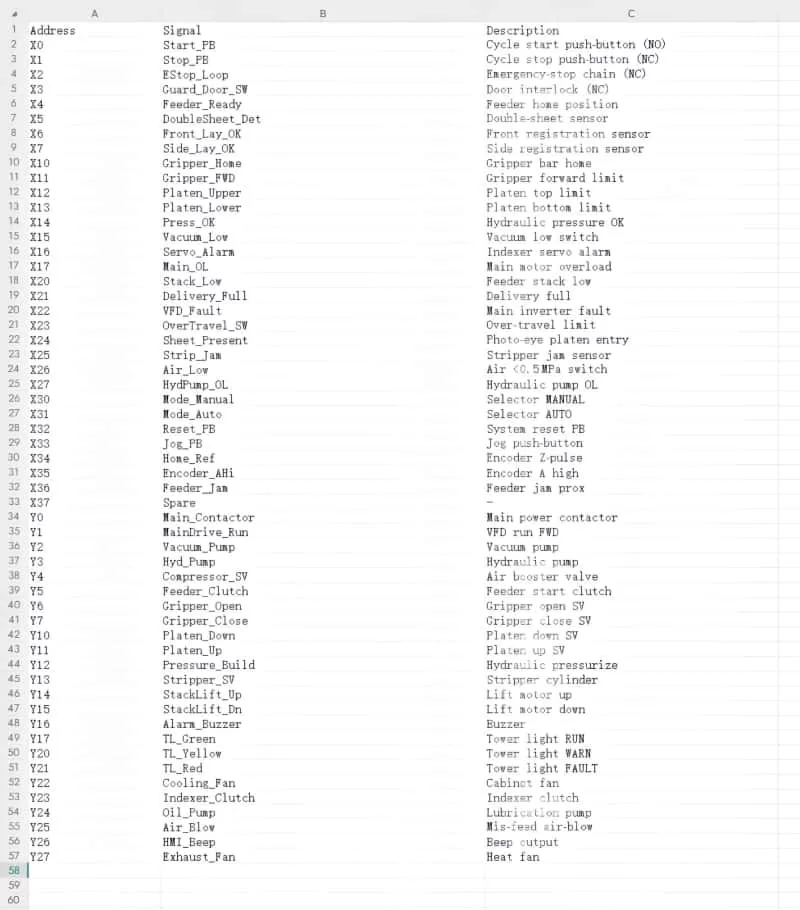
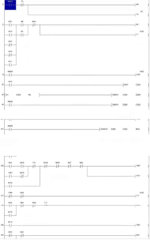
All transition conditions are annotated in the CSV instruction list. High-Speed Interrupt M8252 captures front-guide OK signal every 10 ms to set D404 for auxiliary correction.
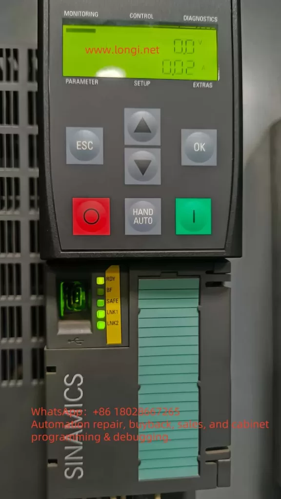
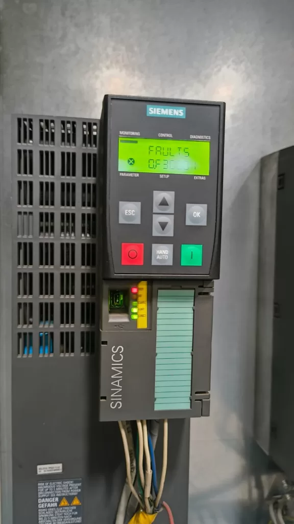
The SINAMICS G120 frequency converter series by Siemens is widely used in industrial automation for its modular structure, flexible control modes, and robust diagnostics. However, during operation, users may occasionally encounter fault codes such as F30001, which can interrupt production or system functionality. This article provides an in-depth explanation of the F30001: Power Unit Overcurrent fault, covering its causes, field-level troubleshooting, internal repair tips, and preventive strategies.
2. Meaning of Fault Code F30001
Definition
F30001 refers to a severe fault in the power module:
“Overcurrent detected by power unit. Output is shut off immediately to protect internal components.”
This is a protective measure triggered when the output current exceeds the safe limit of the power module (typically IGBT modules), preventing hardware damage.
Internal Detection Mechanism
The converter continuously monitors the output current of each phase (U, V, W). The fault is triggered under these conditions:
Phase current exceeds the hardware threshold.
Significant imbalance between the output phases.
Motor stall or sudden torque demands exceed current capacity.
Control loop errors cause false current surges.
Diagnostic parameter r0949 can be used to identify the affected phase (0=unknown, 1=U, 2=V, 3=W, 4=DC bus current).
3. Common Causes of F30001
A. Load-Side Problems
Motor winding short circuit or insulation breakdown.
Damaged or incorrectly connected output cables.
Motor blocked, causing high inrush current.
Converter powered on without connecting a load (not supported in some configurations).
B. Parameter Misconfiguration
Acceleration/deceleration time too short (p1120/p1121).
Incorrect motor parameters (p0300, p0310) lead to wrong current ratings.
Overcurrent response time (e.g. p0974) set too aggressively.
C. Power Supply Issues
Unstable or unbalanced 3-phase input.
Contactors dropping voltage momentarily.
Absence of line reactors leading to high inrush current.
D. Internal Hardware Failures
Damaged IGBT power modules.
Current sensing circuitry failure.
Loose connections or dry solder joints on the driver board.
4. On-Site Troubleshooting and Recommendations
Step 1: Basic Electrical Checks
Use an insulation tester to verify that motor windings have no shorts to ground (usually >1MΩ).
Inspect cables for mechanical damage, aging, or moisture.
Verify correct wiring (star or delta) per motor nameplate.
Step 2: Optimize Control Parameters
Extend acceleration time (p1120) to 5–10 seconds.
Correct the motor’s rated current value (p0310).
Perform motor identification (p1910 = 1) before first start-up.
Avoid no-load testing on some modules.
Step 3: Reset and Re-Test
Clear the fault on the operator panel or through fieldbus.
⚠️ WARNING: Wait at least 5 minutes after power-off to allow DC bus capacitors to discharge.
Disassembly & Inspection:
Open the PM240 cover and check for signs of damage or burn marks.
Measure resistance between U/V/W and DC terminals to detect IGBT short circuits.
Visually inspect drive board connectors and test points for cold joints or oxidation.
If possible, swap power modules or control boards for cross-verification.
6. Preventive Maintenance Tips
Task
Frequency
Clean dust and vents
Monthly
Tighten terminal connections
Quarterly
Check cable insulation
Semi-annually
Monitor current values (r0051)
Continuously
Configure tolerant protection
Initial setup
7. Conclusion
F30001 is a typical fault in SINAMICS G120 that stems from overcurrent events. With proper analysis, parameter optimization, and electrical inspection, most such issues can be resolved at the field level. Technicians must understand not only the electrical behavior of the load but also how the inverter monitors and reacts to current flow.
If the issue persists after external causes are ruled out, contacting our technical support or replacing the power module may be necessary to ensure safety and long-term reliability.
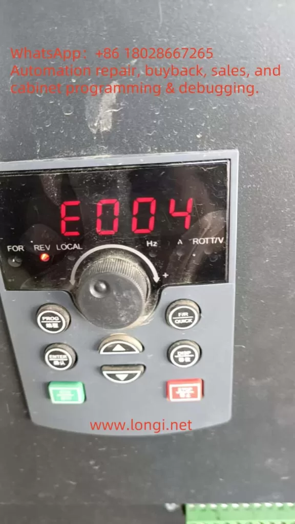
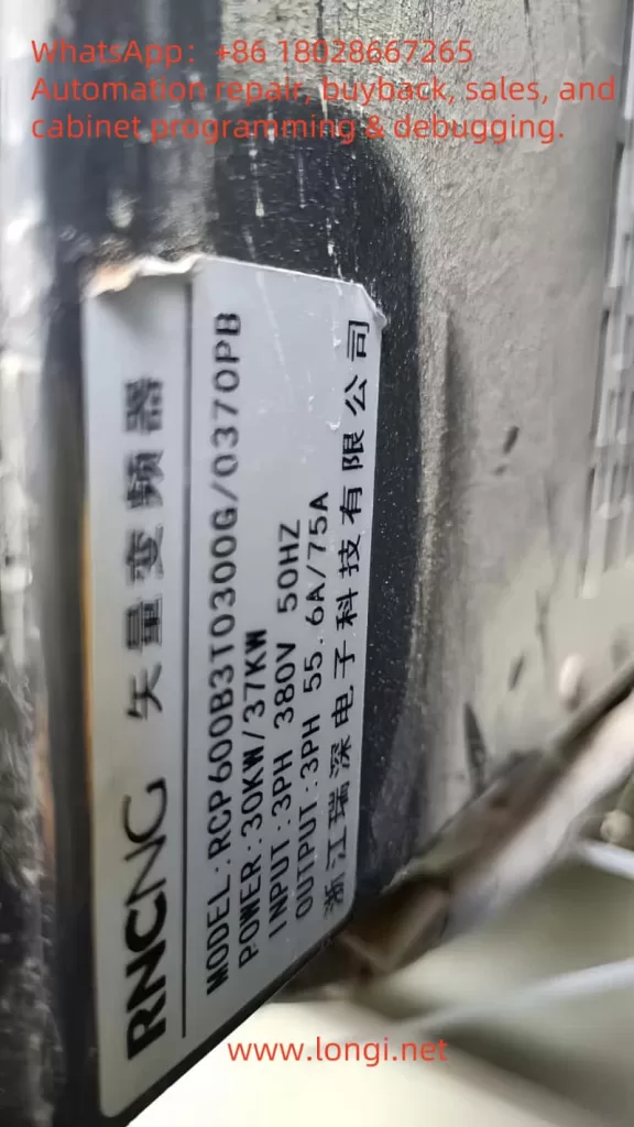
ERR04 is a common fault code for the Ruishen RCP600 series inverter during operation, indicating a constant speed overcurrent issue. This fault is triggered when the inverter detects that the output current continuously exceeds 150% to 200% of the rated value during the constant speed stage (non-acceleration/deceleration process). The fault phenomena include:
Display of “ERR04” or “Constant Speed Overcurrent” alarm on the inverter panel.
Equipment shutdown protection, possibly accompanied by abnormal noise or motor overheating.
The fault can be reset for brief operation but tends to recur.
This fault directly affects the continuous operation capability of the equipment and requires systematic troubleshooting from three aspects: electrical parameters, mechanical load, and hardware status.
II. Fault Cause Analysis and Diagnostic Process
1. Classification of Core Causes
Category
Specific Causes
Parameter Settings
Mismatch of motor parameters (e.g., rated current, number of poles), over-aggressive PID tuning, excessive torque compensation
Load Anomalies
Mechanical jamming, sudden load changes (e.g., drive mechanism failure), increased resistance due to motor bearing damage
Electrical Faults
Output side short circuit/ground fault, cable insulation aging, current detection circuit anomalies (e.g., Hall sensor drift or damage)
Cooling Issues
Poor heat dissipation leading to degraded IGBT module performance and reduced carrier capability
2. Scientific Diagnostic Process
Step 1 – On-site Observation and Data Recording
Record the operating frequency, current value, and DC bus voltage (readable via the panel’s U0 parameter group) at the time of fault occurrence.
Check for abnormal noises, temperature rise, or visible mechanical damage in the motor and mechanical load.
Step 2 – Distinguishing Between Load-Side and Electrical-Side Faults
Disconnect the motor load and run the inverter under no load: If ERR04 disappears, the issue is on the load side; if it persists, check electrical parameters and hardware.
Use a megohmmeter to test the motor winding insulation to ground (requirement: ≥5MΩ) to rule out ground faults.
Step 3 – Parameter Verification and Waveform Analysis
Verify the motor nameplate parameters and check if the P0 group (basic parameters) and A2 group (motor parameters) settings match the actual motor.
Observe the output current waveform for distortions (e.g., excessive harmonics) using an oscilloscope or the inverter’s built-in waveform recording function.
III. Targeted Solutions
1. Parameter Optimization and Adjustment
Motor Self-Learning: Perform the inverter’s “Motor Parameter Auto-Tuning” (refer to the PA group function in the manual) to ensure stator resistance and inductance values match the actual motor.
Reduce Torque Compensation: Adjust the P2-21 parameter (constant speed torque compensation coefficient) and gradually reduce it to 80% to 100% for testing.
PID Parameter Reset: If PID control is applied, reset the PA-03 (proportional gain) and PA-04 (integral time) to their default values to avoid over-tuning.
2. Load-Side Fault Handling
Mechanical System Inspection: Check coupling alignment, bearing lubrication, and belt tension to eliminate jamming points.
Load Matching Verification: Ensure the motor power matches the mechanical load to avoid long-term overload operation. For example, a 22kW motor driving a 30kW load requires an upgraded inverter and motor combination.
3. Electrical Hardware Maintenance
Output Side Insulation Test: Use a 500V megohmmeter to measure the U/V/W terminal insulation to ground. If <5MΩ, replace the motor cable or repair the winding.
Current Detection Calibration:
Check for loose Hall sensor connections.
Recalibrate the current detection accuracy using the AC-20 to AC-27 parameters (analog calibration parameters), with a tolerance deviation within ±2%.
Cooling System Maintenance: Clean the air duct dust, test the cooling fan operation (set temperature threshold via P8-47), and replace aged fans if necessary.
4. Advanced Debugging Techniques
Carrier Frequency Adjustment: Reduce the carrier frequency in the A5-01 parameter (PWM modulation method) (e.g., from 12kHz to 8kHz) to reduce switching losses and temperature rise.
Overcurrent Stall Suppression: Enable the P3-19 (overcurrent stall control) and P3-20 (suppression intensity) parameters, setting the action current to 130% to 150% of the rated value.
IV. Preventive Maintenance Recommendations
Regular Parameter Backup: Utilize the inverter’s “User Parameter Backup” function (P7 group) to save optimized parameters and prevent失调due to accidental resets.
Hardware Inspection Regimen:
Quarterly inspection of output terminal tightness to prevent increased contact resistance.
Annual thermal imaging scan of IGBT modules and rectifier bridges to address abnormal temperature rise points.
Load Monitoring: Install mechanical vibration sensors and current trend recorders for early fault warnings.
V. Maintenance Case Reference
Case Background: An RCP600-22kW inverter for an injection molding machine frequently reported ERR04, operating normally under no load but triggering the fault after 10 minutes under load.
Troubleshooting Process:
No-load current was 12A (normal), but under load, it rose to 48A (rated current 42A).
Motor insulation test was normal, but disassembly revealed rusted and jammed reducer bearings.
After replacing the bearings and adjusting the P2-21 parameter (torque compensation) from 150% to 110%, the fault was resolved.
VI. Summary
Resolving the ERR04 fault requires a three-tiered troubleshooting approach focusing on “parameters, load, and hardware,” combined with real-time data and equipment status analysis. The key is to distinguish between transient overcurrent and sustained overload, avoiding unnecessary component replacements. Through scientific debugging processes and preventive maintenance, the stability of the inverter system can be significantly improved, reducing the risk of unplanned downtime.
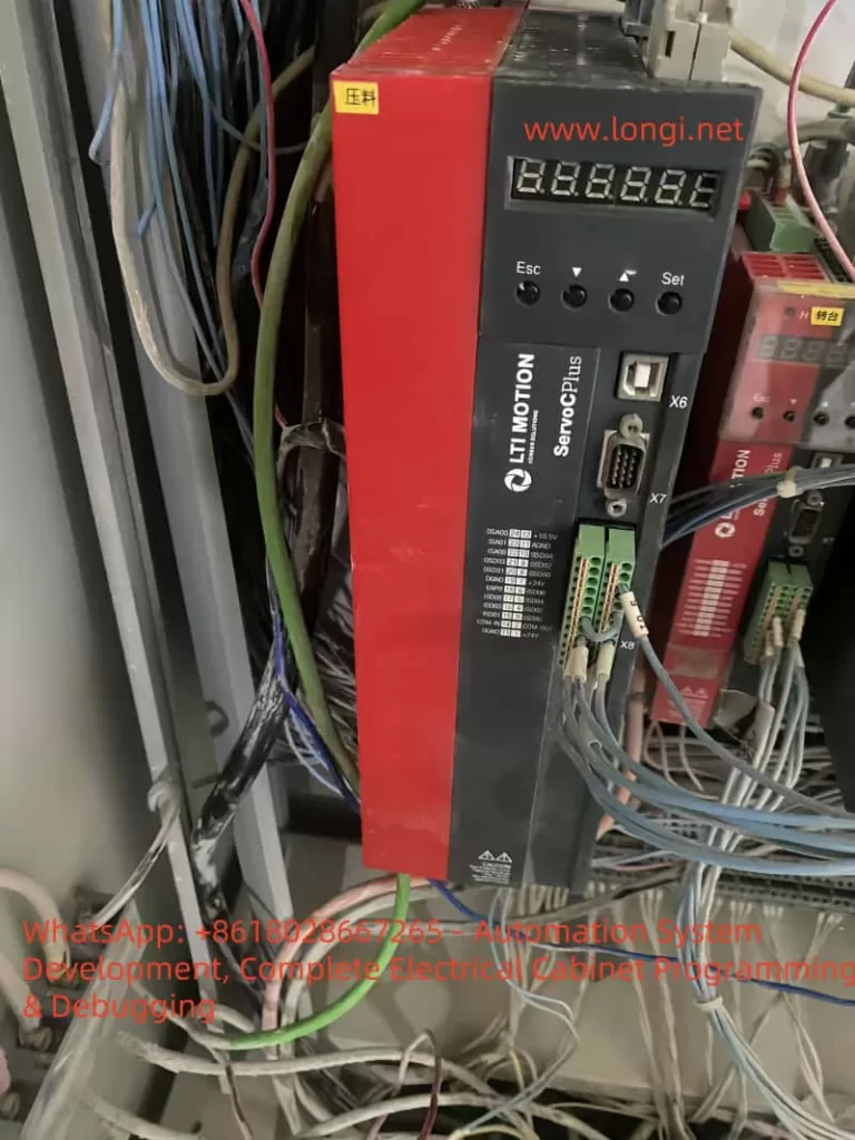
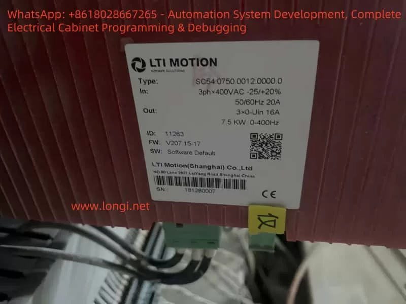
1. Overview Ceramic rolling forming equipment is a typical multi-axis automatic machine widely used in the initial pressing of electronic, structural, and functional ceramics. The system usually consists of a servo control unit, electrical control system, pneumatic components, and a rolling head. This document introduces in detail how to apply the LTI Motion ServoC series servo drive in combination with the Mitsubishi FX3U series PLC, covering the application strategy, wiring diagram, parameter configuration, and control logic.
2. Application Scenario and System Structure This system involves two servo control units:
Pressing Axis Servo: Drives the pressing roller vertically to compress ceramic blanks.
Rotary Table Servo: Controls intermittent indexing of the rotary table for sequential forming.
3. Key Functional Requirements
Precise positioning of the pressing head for consistent product thickness.
Indexing rotation of the rotary table with accurate angular control.
Multi-sensor interlock with limit switches and origin sensors.
Safety integration with emergency stops, alarms, and feedback loops.
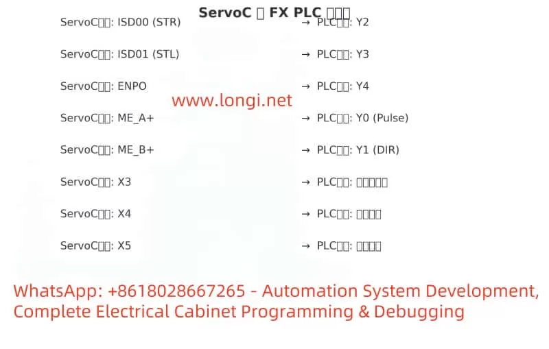
P152 = 1 or 2: Set input mode to pulse+direction or I/O trigger
P210 = 2; P211 = 3: Set ISD00 to STR, ISD01 to STL
P483 = 2 or 3: Motor direction configuration
P759 / P760: Software limit for press upper/lower bounds
P803: Position error tolerance
7. Control Logic Sequence
Power ON → Y4 output to enable servos.
Origin detection via X3 → Set M10 (homed flag).
Start pressing:
X0 input triggers Y2 = ON (STR), Y3 = OFF (STL).
X4 bottom sensor triggers M20.
Return press head:
X1 input triggers Y3 = ON (STL), Y2 = OFF.
Rotate table:
X2 input + M20 triggers 2000 pulses via Y0 and DIR = Y1.
X5 confirms rotation complete (M31).
8. Ladder Diagram (Simplified)
LD M8013
OUT Y4 ; Servo Enable

LD X3
OUT M10 ; Homed flag

LD X0 AND M10
OUT Y2
RST Y3

LD X1 AND M10
OUT Y3
RST Y2

LD X4
OUT M20

LD X2 AND M20
RST M20
SET Y1
PLS Y0 K2000

LD X5
OUT M31
RST M30
9. Diagrams and Application Notes
10. Conclusion and Recommendations This solution demonstrates the application of ServoC servo drives in high-precision ceramic roller forming machines using Mitsubishi FX3U PLCs.
Best Practices:
Set software travel limits.
Implement emergency stops and feedback alarms.
Always home the servo before operation.
Use opto-isolated I/O to reduce interference.
Future Extensions:
Integrate HMI for parameter recipes and alarms.
Add pressure sensors and linear encoders for quality control.
Expand to multi-station synchronization with communication protocols.
The BioSpectrum AC Chemi HR 410 is a versatile gel and chemiluminescence imaging platform widely used in molecular biology and biochemistry laboratories. This article synthesizes hardware specifications, software capabilities, common applications, troubleshooting methodologies, market pricing, installation considerations, and support resources into a coherent, step-by-step guide. Whether you’re commissioning a new system, refurbishing a second-hand unit, or diagnosing intermittent black-frame issues, this document provides the logical framework and detailed procedures to keep your imaging workflow running smoothly.
1. System Overview
The BioSpectrum AC Chemi HR 410 (often abbreviated “HR 410”) is manufactured by Analytik Jena (formerly UVP). It combines a fully enclosed dark chamber, interchangeable light sources, a high-sensitivity cooled CCD camera, and the user-friendly VisionWorks software. Typical applications include:
DNA/RNA electrophoresis imaging with EtBr or SYBR dyes
Protein blot detection via chemiluminescence (ECL) or fluorescence
Quantitative analysis of band densities (1D) and area densities (2D)
Plate and dish imaging using transmitted or reflected light
Key advantages are its modular optical design, precise filter-wheel control, and advanced image-processing algorithms. The system supports both manual and automated modes, making it suitable for single-user labs up to core facilities.
2. Hardware Components and Operating Principles
Dark Chamber
Dimensions: ~445 mm (W) × 445 mm (D) × 813 mm (H). Completely light-tight to prevent ambient interference.
Illumination Module (T-Lum Platform)
Houses ultraviolet (254 nm, 302 nm) or white LED arrays. Enables rapid switch-out of lamp assemblies.
Models labeled “Without T-Lum” require separate procurement of the light-source kit.
Filter Wheel and Shutter
Motorized carousel holds multiple excitation and emission filters for fluorescence; includes an interlock shutter to block or permit light.
CCD Camera (Chemi HR 2 MP)
High quantum-efficiency, Peltier-cooled CCD. Cooling reduces dark current, enabling long exposures (seconds to minutes) with minimal noise.
Interface and Control
230 VAC power input, USB and Ethernet ports. Can be tethered to a dedicated workstation or shared network PC.
Chassis and Ergonomics
Top-mounted camera head with adjustable focus; front door for sample insertion; side vents for cooling airflow.
This modular architecture allows each component to be serviced or upgraded independently—critical for maintaining peak performance over years of operation.
3. VisionWorks Software Features
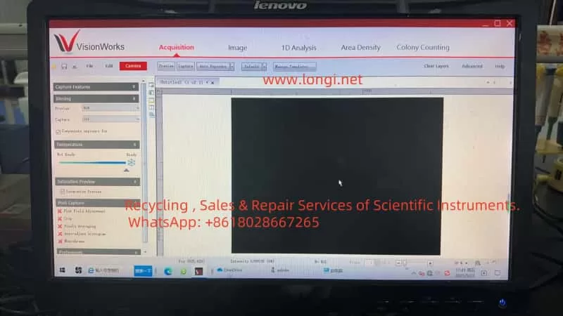
VisionWorks is the proprietary acquisition and analysis suite for HR 410. Major modules include:
Acquisition Modes:
Preview: Real-time low-exposure view for focusing and framing.
Capture: Manual control of exposure time, gain, and shutter.
Auto-Exposure: Algorithmic calculation of optimal exposure based on selected template (e.g., DNA, chemiluminescence).
Image Management:
Zoom, pan, ROI selection, frame stacking, and pixel averaging to enhance weak signals.
Quantitative Analysis:
1D Analysis: Automated lane/band detection, background subtraction, area integration.
2D Area Density: Intensity heatmaps and contour plots for flat samples.
Template System:
Save and recall complete acquisition and analysis parameters for reproducible experiments.
Calibration Utilities:
Dark Reference Acquisition: Captures a baseline image with shutter closed to subtract sensor noise.
Flat Field Adjustment: Corrects for uneven illumination or vignetting across the field of view.
Intuitive menus and clear graphical feedback make VisionWorks accessible to both novice and expert users.
4. Common Application Workflows
Nucleic Acid Gel Imaging
Stain with Ethidium Bromide or SYBR dye; select appropriate excitation filter and emission barrier filter.
Use Preview to position the gel, then Auto-Exposure or manual exposure (0.5–10 s) depending on band brightness.
Western Blot Chemiluminescence
Mount blot on trans-illumination tray, close door, then select “Chemiluminescence” template.
Exposures may range from 30 s to several minutes for low-abundance proteins.
Quantitative Band Analysis
After capture, launch 1D Analysis: draw lanes, verify band boundaries, subtract local background, and export intensity values.
High-Throughput Plate Imaging
Use white LED for trans-illumination of microplates; flat-field correction ensures uniform signal across wells.
These workflows can be chained in batch mode for unattended overnight acquisition.
5. Fault Phenomena and Root Cause Analysis
5.1 Completely Black Frames
Missing Illumination Module: Units sold “Without T-Lum” lack any light source; image is always black.
Lamp or LED Failure: Old or damaged bulbs/LEDs fail to ignite, leaving no excitation light.
Unready CCD Cooling: Camera not cooled to setpoint; software suspends exposure to avoid noise.
Filter or Shutter Misalignment: Filter wheel stuck in blank position or shutter never opens.
5.2 Intermittent Weak Signal
Lamp Aging: Mercury-arc bulbs degrade over time; sometimes they ignite, sometimes they don’t.
Calibration Expiry: Dark or flat references become outdated, leading to improper noise subtraction and vignetting artifacts.
Understanding these categories allows targeted troubleshooting rather than trial-and-error.
6. Step-by-Step Troubleshooting and Maintenance Workflow
Verify Illumination Presence
Check rear panel or documentation for T-Lum module; if absent, acquire and install the correct kit.
Test and Replace Lamps/Ballasts
Preheat lamp for 5–10 min; observe light output. Measure ballast voltage. Replace any bulb nearing 800–1 000 h lifetime.
Ensure CCD Cooling and Calibration
Wait for “Temperature: Ready” indicator. In the software, navigate to Image → Calibration and Acquire Dark Reference. Then enable Flat Field Adjustment.
Optimize Exposure Settings
Run Auto-Exposure in the “Chemiluminescence” template. If still dim, manually increase exposure to 60–300 s. Disable “Compensate exposure for” to test pure manual mode.
Maintain Filter Wheel and Shutter
Cycle through all filter positions in software; listen for smooth motor sounds. Clean filter edges and apply micro-drops of non-oil lubricant to bearings as needed.
Update Software and Firmware
Download the latest VisionWorks patches and camera firmware from the manufacturer’s website. Reboot system to apply changes.
Clean Optical Path and Sample Holders
Wipe lenses, trays, and windows with lint-free wipes and 70% ethanol. Verify that sample trays align with the camera’s field of view.
By following this structured workflow, most “black frame” or “fluctuating signal” issues can be resolved without resorting to full system teardown.
7. Market Selection and Pricing Reference
Configuration
Typical Second-Hand Price (USD)
New Unit MSRP (USD)
Notes
Dark Chamber Only (no camera, no software)
800 – 1 500
N/A
For UV fluorescence only, no chemiluminescence
Refurbished Complete System (HR 410 + Software)
5 000 – 6 000
N/A
Often sold with limited warranty
Brand-New Complete System (HR 410 + License + T-Lum)
N/A
8 000 – 12 000
Official distributor pricing
Recommendation:
Budget-Conscious Labs: Opt for a fully refurbished unit with warranty coverage.
Core Facilities or High-Throughput Settings: Invest in a brand-new system for guaranteed support, full warranty, and latest firmware.
8. Installation Footprint and Environmental Requirements
Dark Chamber Dimensions: 445 mm × 445 mm × 813 mm
Overall Footprint (including camera head): 623 mm × 463 mm × 915 mm
Space Planning: Reserve at least 300 mm clearance front and back, 500 mm on sides for maintenance access.
Ambient Conditions:
Temperature: 18 °C – 25 °C
Relative Humidity: ≤ 60%
Avoid direct sunlight or strong fluorescent lighting near the sample door.
Proper environmental control reduces temperature fluctuations on the CCD and extends component life.
9. Supporting Documentation and Technical Assistance
Official Manual:BioSpectrum Imaging System Instruction Guide (Part 81-0346-01 Rev J) contains detailed hardware schematics, software installation, calibration procedures, and maintenance guidelines.
Contact Analytik Jena’s regional distributor for spare parts (lamps, filters, shutters).
Access online firmware updates and knowledge-base articles via the official website.
Enroll in extended service contracts for on-site preventive maintenance.
10. Conclusion and Best Practices
The BioSpectrum AC Chemi HR 410 combines optical versatility, sensitive detection, and powerful analysis software to serve a broad range of life-science imaging applications. By adhering to the systematic maintenance workflow outlined above, users can:
Prevent Downtime: Regular lamp replacement, calibration refreshes, and filter-wheel lubrication.
Ensure Data Quality: Proper dark/flat corrections and exposure optimization guarantee reproducible results.
Extend System Life: Keeping software and firmware up to date, cleaning optical components, and controlling environmental factors.
When selecting a unit, balance budgetary constraints against the need for warranty and technical support. For intermittent imaging issues—such as occasional black frames or weak signals—follow the seven-step troubleshooting procedure before involving service engineers. In doing so, your laboratory will realize maximum uptime, consistent image quality, and reliable quantitative data for years to come.