Abstract
The Anchuan G9300 series frequency inverter is a high-performance vector inverter widely used in various industrial automation applications. This article will provide a detailed introduction to the operation panel functions, parameter settings, password management, external terminal control, and fault codes and their solutions for the G9300 series frequency inverter, helping users better understand and utilize this equipment.

1. Operation Panel Function Introduction
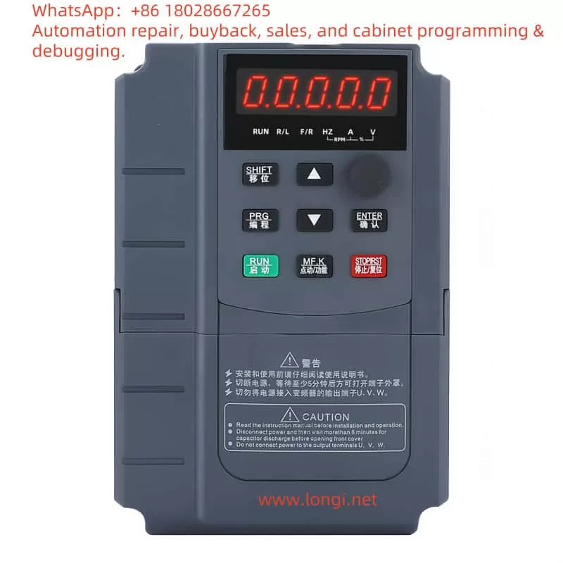
The operation panel of the Anchuan G9300 series frequency inverter is designed to be simple and functional, mainly consisting of the following parts:
- Display Screen: Used to display current operating status, parameter settings, and other information.
- Function Keys: Include PRG (Programming Key), ENTER (Confirm Key), SHIFT (Shift Key), RUN (Start Key), STOP/RST (Stop/Reset Key), and MF.K (Multi-Function Key).
- Increment and Decrement Keys: Used to adjust parameter values or browse menus.
1.1 Restoring Factory Settings
Before using the G9300 series frequency inverter, it is usually necessary to restore the parameters to factory settings to ensure the device is in a known state. Here are the steps to restore factory settings:
- Enter Parameter Setting Mode: Press the PRG key to enter the first-level menu, then press the ENTER key to enter the second-level menu.
- Select Parameter Initialization Function: In the second-level menu, find the PP-01 (Parameter Initialization) function code.
- Restore Factory Parameters: Set PP-01 to 1, then press the ENTER key to confirm. At this point, all parameters of the frequency inverter will be restored to factory settings.
1.2 Setting and Removing Passwords
To protect parameter settings from being arbitrarily changed, the G9300 series frequency inverter provides a password protection function. Here are the steps to set and remove passwords:
- Setting a Password:
- Enter the parameter setting mode and find the P7-11 (User Password) function code.
- Set P7-11 to the desired password value (range 0~32766), then press the ENTER key to confirm.
- Removing a Password:
- Enter the parameter setting mode and find the P7-11 function code.
- Set P7-11 to 0, then press the ENTER key to confirm, and the password will be removed.
1.3 Parameter Access Restrictions
To further protect parameter settings, the G9300 series frequency inverter also provides a parameter locking function. Here are the steps to set parameter access restrictions:
- Locking Parameters:
- Enter the parameter setting mode and find the PP-04 (Parameter Lock) function code.
- Set PP-04 to 1, then press the ENTER key to confirm. At this point, all parameters will be locked and cannot be changed.
- Unlocking Parameters:
- Enter the parameter setting mode and find the PP-04 function code.
- Set PP-04 to 0, then press the ENTER key to confirm, and the parameter lock will be removed.
2. External Terminal Forward/Reverse Control and External Potentiometer Speed Regulation
The G9300 series frequency inverter supports forward/reverse control and potentiometer speed regulation through external terminals, making it very flexible and convenient in industrial automation control.
2.1 External Terminal Forward/Reverse Control
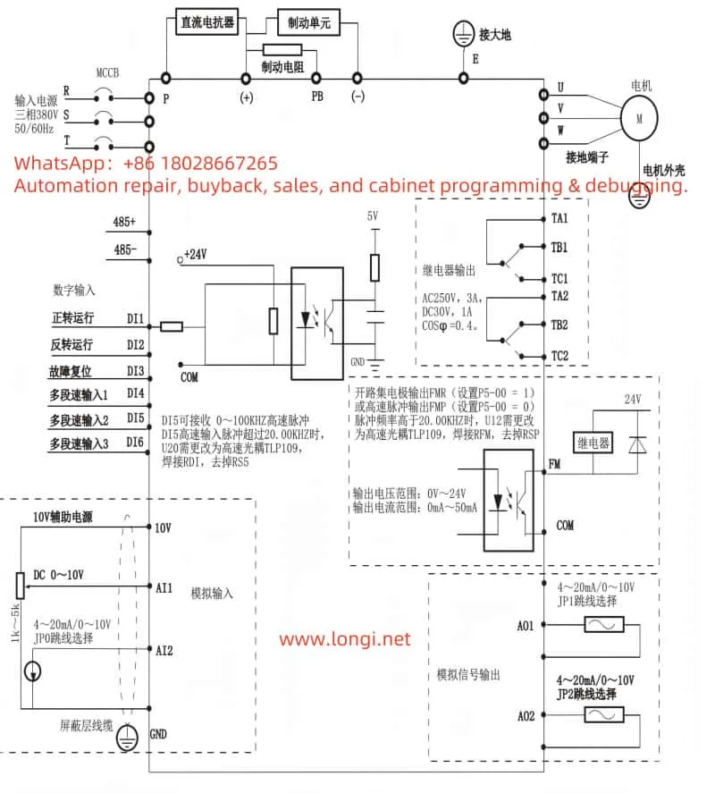
To achieve external terminal forward/reverse control, the following wiring and parameter settings are required:
- Wiring:
- Connect the forward control signal to the DI1 terminal.
- Connect the reverse control signal to the DI2 terminal.
- Ensure the ground terminal (GND) is correctly connected.
- Parameter Settings:
- Enter the parameter setting mode and find the P4-00 (DI1 Terminal Function Selection) and P4-01 (DI2 Terminal Function Selection) function codes.
- Set P4-00 to 1 (Forward Operation), and P4-01 to 2 (Reverse Operation), then press the ENTER key to confirm.
2.2 External Potentiometer Speed Regulation
To achieve external potentiometer speed regulation, the following wiring and parameter settings are required:
- Wiring:
- Connect the output of the potentiometer to the AI1 terminal.
- Ensure the ground terminal (GND) is correctly connected.
- Parameter Settings:
- Enter the parameter setting mode and find the P0-03 (Main Frequency Source A Selection) function code.
- Set P0-03 to 4 (Keypad Potentiometer), then press the ENTER key to confirm.
3. Fault Codes and Their Solutions
During the use of the G9300 series frequency inverter, various faults may be encountered. Here are some common fault codes and their solutions:
| Fault Code | Fault Description | Solution |
|---|---|---|
| E001 | IGBT Short Circuit Fault | Check the IGBT module and its drive circuit, replace the IGBT module if necessary. |
| E002 | Acceleration Overcurrent | Check if the acceleration time setting is too short or if the load is too large, adjust the acceleration time or reduce the load. |
| E003 | Deceleration Overcurrent | Check if the deceleration time setting is too short or if the load is too large, adjust the deceleration time or reduce the load. |
| E004 | Constant Speed Overcurrent | Check if the load is too large or if the motor parameters are set correctly, reduce the load or reset the motor parameters. |
| E005 | Acceleration Overvoltage | Check if the acceleration time setting is too short or if the bus voltage is too high, adjust the acceleration time or check the bus voltage. |
| E006 | Deceleration Overvoltage | Check if the deceleration time setting is too short or if the bus voltage is too high, adjust the deceleration time or check the bus voltage. |
| E007 | Constant Speed Overvoltage | Check if the bus voltage is too high or if the load is too small, adjust the bus voltage or increase the load. |
| E008 | Stop Overvoltage | Check if the stop mode setting is correct or if the bus voltage is too high, adjust the stop mode or check the bus voltage. |
| E009 | Undervoltage | Check if the input voltage is normal or if the power line is in good contact, ensure the input voltage is stable. |
| E010 | Inverter Overload | Check if the load is too large or if the heat dissipation is good, reduce the load or improve the heat dissipation conditions. |
| E011 | Motor Overload | Check if the motor load is too large or if the heat dissipation is good, reduce the load or improve the heat dissipation conditions. |
| E012 | Input Phase Loss | Check if the input power supply is missing a phase, ensure all three phases are normally powered. |
| E013 | Output Phase Loss or Three-Phase Output Imbalance | Check if the output line is normal, ensure the three-phase output is balanced. |
| E014 | Module Overheat | Check if the heat sink is blocked or if the ambient temperature is too high, ensure good heat dissipation. |
| E015 | External Fault | Check if the external control line is normal, ensure the external control signal is correct. |
| E016 | Communication Abnormality | Check if the communication line is normal or if the communication parameters are set correctly, ensure stable communication. |
| E017 | Motor Tuning Abnormality | Check if the motor parameters are set correctly, re-perform motor tuning. |
| E018 | Parameter Read/Write Abnormality | Check if the parameter settings are correct, reset the parameters. |
| E019 | Inverter Hardware Abnormality | Check if the inverter hardware is normal, contact after-sales service if necessary. |
| E020 | Motor Ground Short Circuit | Check if the motor line is short-circuited, ensure the motor insulation is good. |
| E021 | AD Zero Drift Too Large | Check if the analog input circuit is normal, contact after-sales service if necessary. |
| E022 | Inverter Hardware Abnormality (Clear Latch Timeout) | Check if the inverter hardware is normal, contact after-sales service if necessary. |
| E023 | Motor Ground Short Circuit | Check if the motor line is short-circuited, ensure the motor insulation is good. |
| E024 | AD Zero Drift Too Large | Check if the analog input circuit is normal, contact after-sales service if necessary. |
| E025 | User-Defined Fault 1 | Check if the setting of user-defined fault 1 is correct, ensure the logic is correct. |
| E026 | User-Defined Fault 2 | Check if the setting of user-defined fault 2 is correct, ensure the logic is correct. |
| E027 | Power-On Time Reached | Check if the power-on time setting is correct, adjust the power-on time appropriately. |
| E028 | PID Feedback Disconnection Fault | Check if the PID feedback line is normal, ensure the feedback signal is stable. |
| E029 | PID Feedback Overlimit (Overvoltage) Fault | Check if the PID feedback signal is too large, adjust the PID parameters appropriately. |
| E030 | Keypad STOP Key Stop Fault | Check if the STOP key is normal, ensure the control logic is correct. |
| E031 | Hardware Current Limit Timeout | Check if the current limit setting is correct or if the load is too large, adjust the current limit parameters or reduce the load. |
| E032 | Auto-Reset Count Exceeded | Check if the auto-reset count setting is correct, adjust the reset count appropriately. |

4. Conclusion
The Anchuan G9300 series frequency inverter is a powerful and high-performance industrial automation device. Through this article, users can better understand and use this equipment, including operation panel functions, parameter settings, password management, external terminal control, and fault codes and their solutions. In practical applications, users should perform parameter settings and fault troubleshooting according to specific needs to ensure the stable operation and high efficiency of the equipment.
It is hoped that this article can help users better master the usage methods of the Anchuan G9300 series frequency inverter and improve the efficiency and quality of industrial automation control.
