
Problem Description
A Zoller smartCheck 450 fully automatic tool presetter (tool measuring machine) encountered issues where the C-axis failed to rotate and triggered program error alarms during measurement. The user confirmed that no software updates, circuit modifications, or maintenance operations had been performed recently, and the fault persisted after power cycling. Below is a comprehensive analysis of potential causes from aspects such as electrical control failures, encoder/motor issues, software configuration errors, sensor abnormalities, and limit/emergency stop signals, along with corresponding troubleshooting steps and solutions.
1. Electrical Control Cabinet Connection and ZUB Drive Inspection
Possible Causes
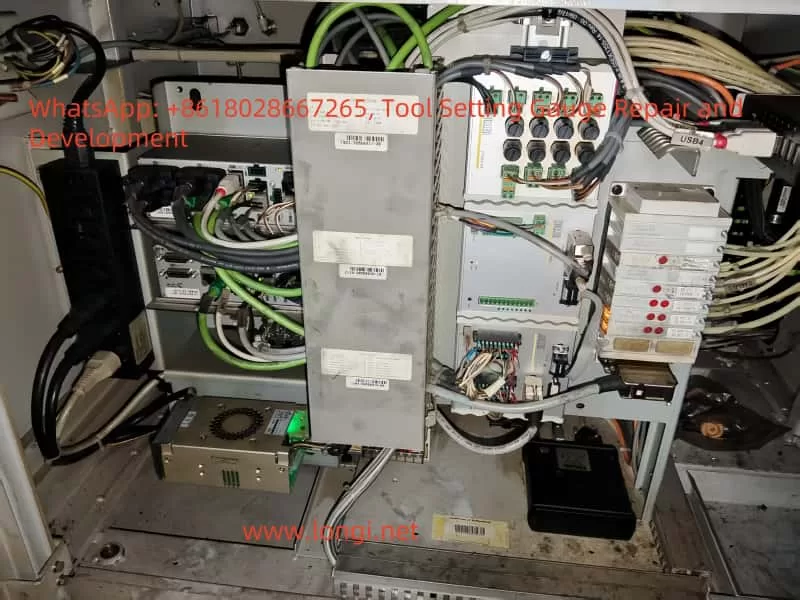
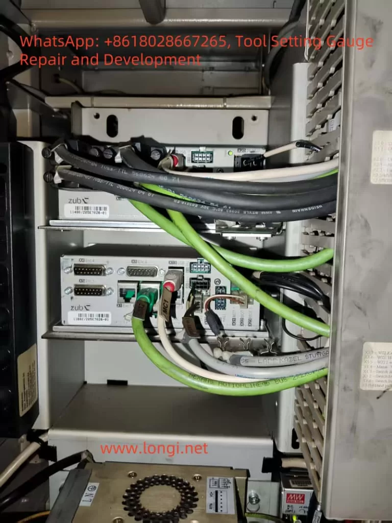
- The C-axis drive signal may not be transmitted properly, often due to loose wiring or power supply failures in the drive. The Zoller smartCheck series typically uses ZUB multi-axis motion control/drive modules to control the X/Z/C axes. Photos of the electrical control cabinet show a drive board labeled “zub” with thick cables MC1, MC2, etc. (presumably motor power and encoder/feedback lines). If these connections are loose, poorly contacted, or broken, the C-axis motor will not receive driving torque or feedback signals, preventing the C-axis from rotating.
Inspection Points
- Drive Connections: First, power off the machine and open the electrical control cabinet to inspect all connectors related to the C-axis on the ZUB drive. Pay special attention to whether the MC1 and MC2 cable interfaces are firmly plugged in, whether the plug locking mechanisms are in place, and whether there are signs of burn damage, discoloration, or breakage on the plugs and cables. If necessary, disconnect and reconnect them to ensure good contact. Also, check the normal connection of other drive interfaces (such as encoder interface X3, bus interface X8, etc.).
- Drive Indicators: Check the status indicators or digital displays (if any) on the ZUB drive module. Drives usually have power indicators and fault alarm lights. If there is a fault in the C-axis drive section, a red light may illuminate or an error code may be displayed. Record any abnormal indications for further consultation with the manufacturer’s technical documentation or support engineers.
- Drive Power Supply: Confirm that the drive power supply is normal. Measure the DC bus voltage or 24V control power supply of the drive (which should be supplied by the switching power supply in the control cabinet). Check whether there are fuses or electronic circuit breaker modules in the control cabinet that control the drive power output. For example, if electronic fuse modules such as Murr are installed in the cabinet, check whether the corresponding channel indicator lights are tripped due to overload (red light constantly on). If tripped, reset or replace the fuses according to the module instructions.
- Grounding and Shielding: Ensure that the grounding wires of the drive and motor are well connected. Loose grounding or shielding wires can introduce electrical noise and interfere with encoder signals, causing abnormal axis operation.
2. Zoller Control Module (Z1001/Z1004) Status
Possible Causes
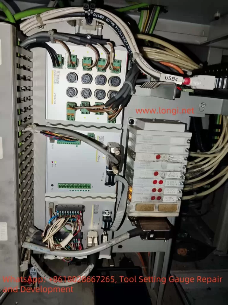
- In addition to the main drive, there are control modules labeled Zoller Z1001 and Zoller Z1004 PZ in the electrical control cabinet. These modules may be responsible for signal distribution, I/O interfaces, or special functions (such as pneumatic control and sensor amplification). If these modules are related to C-axis control, their faults or poor contacts can also cause the C-axis to be uncontrollable.
Inspection Points
- Module Indicators: Observe the LED indicator states on the Z1001 and Z1004 modules. Normally, these modules should have a constant power indicator (green). In case of a fault, the modules may display a red fault light or flashing codes. Pay special attention to whether there are abnormal indications on modules related to C-axis control (such as Z1004 PZ, which may be related to the rotary axis or pneumatic braking).
- Wiring Terminals: Gently press the wiring terminals and plugs on each module with your hands to check for looseness. There are multiple rows of wiring on the Z1001/1004 modules. If some signal lines related to C-axis control (such as limit sensors, zero-position sensors, and braking solenoid valves) are loose, the C-axis action will be affected. Retighten all screw terminals and plugs to ensure a reliable connection.
- Module Functions: Refer to the module manuals for inspection if available. For example, the Z1004 PZ may be a “rotary table control module” (assuming PZ stands for “Prüf-Z Achse” or similar), which may have multiple adjustable potentiometers or fuses. If these fuse elements have tripped, reset or replace them as required. Similarly, the Z1001 may be the main control interface board, and its fault will affect the entire control logic. Check the appearance of these modules for burn damage or component脱落 (detachment). If module damage is suspected, contact Zoller after-sales service for further diagnosis.
3. C-Axis Motor and Encoder Faults
Possible Causes
- Mechanical or electrical faults may occur in the drive components of the C-axis itself, including motor damage, encoder signal loss, and axis brake not releasing. These will directly cause the axis to be unable to rotate and trigger errors during program execution.
Motor Faults
- If the C-axis motor has coil burnout, winding short-circuit, or bearing seizure, it will not rotate. In this case, the drive will usually report axis drive faults or short-circuit/overload alarms. Check whether the motor body is overheated, discolored, or has an abnormal odor. Manually rotate the spindle slightly (after ensuring safety and releasing the brake) to feel for excessive resistance or jamming. If the motor is severely damaged, it needs to be repaired or replaced.
Encoder Signal Interruption
- The C-axis requires an encoder to provide angle feedback. If the encoder is damaged or its signal line is interrupted, the drive will not be able to detect the position and will usually report a large position error or encoder fault alarm, causing the axis to be shut down for protection.
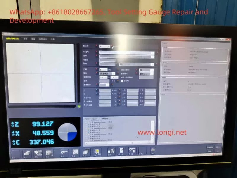
- Verification Method: Observe whether the C-axis angle reading on the Xpilot software interface changes. Slightly rotate the C-axis after power-off (after ensuring that the brake is released) and then power on to see if the software angle value changes; or manually read the value using the software without triggering the program. If the reading remains constant or changes abnormally, the encoder may have no feedback. In this case, check whether the encoder connection (usually through the MC2 cable) is loose. If necessary, use a multimeter to test the encoder power supply voltage or use an oscilloscope to check the encoder signal quality (this requires the intervention of professionals).
Brake Not Released
- Many measuring machines have electromagnetic or pneumatic brakes on the C-axis to lock the spindle and prevent rotation (to improve measurement accuracy). During rotation, the controller should unlock the brake. If the brake is stuck or does not receive the unlock command, the motor will be mechanically locked and unable to rotate.
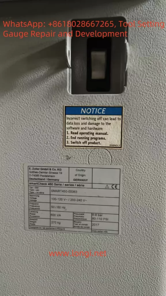
- Troubleshooting Measures: Listen for the sound of the brake action when the C-axis attempts to rotate (electromagnetic brakes usually make a “click” sound, and pneumatic brakes make an airflow sound). Check whether the solenoid valve or relay that controls the brake works (the corresponding Z1001/1004 module may drive the brake signal). Also, confirm the air pressure: The nameplate of this model indicates that a 6-8 bar air source is required. If the air pressure is insufficient or the air circuit is blocked, the pneumatic brake cannot be released. Check whether the air pressure gauge reading is normal and whether there are air leaks or damages in the relevant air pipes. For electromagnetic brakes, measure whether there is approximately 24V voltage at its power supply terminals when the axis is enabled; if there is no voltage, it means that the control signal is not output, and the control circuit should be checked.
Mechanical Jamming
- After excluding the above electrical problems, it is not ruled out that the C-axis transmission mechanism is mechanically jammed (such as gear jamming or the clamping mechanism not being fully released). Under the premise of powering off and ensuring safety, manually rotate the C-axis to check its smoothness. If it is obviously unable to rotate and the influence of the brake is excluded, inspect the spindle transmission mechanism for foreign object blockage or damage.
4. Software Configuration and Program Logic Inspection
Possible Causes
- Software configuration errors or logical conflicts can also cause the C-axis to not rotate and program errors. For example, improper axis parameter configuration in the Xpilot (Pilot 3.0) software or problems in the program flow logic. Although the user stated that no software updates have been performed, the following situations still need to be considered:
Axis Parameter Configuration
- Enter the machine configuration menu in the Zoller Pilot software and check whether the C-axis is correctly identified and activated. For example, check parameters such as the travel range, zero-point position, and whether CNC control is enabled for the C-axis. Is it possible that the configuration file is damaged or parameters are lost, causing the C-axis to be uncontrolled (for example, abnormal internal controller axis card parameters)? If the configuration is found to be incorrect, restore the correct parameters (refer to the factory backup or contact the manufacturer for information). Pay special attention to the zero-point/reference point setting: Some devices require returning to zero at startup. If the software does not execute the return-to-zero operation and attempts to rotate, an error may be reported. Ensure that the reference points of each axis are initialized according to the correct procedure.
Program Logic Errors
- Review the measurement program (Sequence) that reported the error. Look for error prompts in the log at the bottom of the Xpilot interface. If the program reports an error at the step where the C-axis motion is called, it may be due to unsatisfied logical conditions. For example, the software may detect that a safety condition is not met (such as the tool not being clamped or exceeding the measurement range) and skip or abort the C-axis rotation. Verify whether the tool is correctly clamped and whether the tool parameters (such as tool length and diameter) in the software are within the allowable range to prevent the program from stopping due to the protection mechanism. You can also try to rotate the C-axis manually: Is there a manual JOG or specific function in the Pilot software to rotate the C-axis? If it cannot be rotated manually, it can basically be determined as a hardware/safety lock problem; if it can be rotated manually but not in the program, there may be a program logic error. In this case, consider re-recording the measurement sequence or checking the C-axis commands in the script.
Software Fault Reset
- If a software status abnormality is suspected (such as a cache error causing logical confusion), try to reinitialize the software. Close the Xpilot program and turn off the power supply of the industrial control computer. Wait a moment and then restart it to let the control system re-power on and initialize. If the software provides system diagnosis or reset options (such as the Pilot software may have diagnostic tools), run them to detect configuration errors. If necessary, consider backing up the data and then reinstalling or upgrading the software to a stable version to fix potential program bugs.
Internal Controller Parameters
- The motion control of some Zoller devices may be based on third-party CNC systems (for example, some cases mention that axis board parameter errors in the Syntec CNC system cause IO failures). Although the user has not changed the parameters, it is not ruled out that the controller parameters are disordered due to battery power failure or other reasons. If this situation is suspected, an engineer with permission should enter the controller debugging interface to verify the parameters of each axis, especially the drive configuration and feedback configuration of the C-axis.
5. Sensor Status and Safety Circuit Inspection
Possible Causes
- Abnormalities in safety protection and position sensors can also cause the C-axis to be locked and unable to rotate, commonly including false alarms from limit switches, unreset emergency stop circuits, and actions of other safety interlocks (such as protective doors and tool clamping sensors).
Limit Switches/Reference Point Sensors
- Confirm the status of the limit or zero-position sensors of the C-axis. Some tool presetters’ rotary tables may have zero-position sensors or limit switches with limited rotation ranges. If these sensors fail (for example, if the line of a normally closed switch is disconnected, the system will consider it to be in the over-limit position), the control system will prohibit the axis from continuing to move. Check the status of each input signal through the diagnosis interface of the Pilot software: Whether the C-axis limit is triggered (it should be in the normal untriggered state). If necessary, use a multimeter to measure the on-off state of the relevant sensors or lightly拨 (move) the sensor trigger plate to see if the status changes in the software to judge whether the sensor is stuck or the signal line is broken. If a sensor is found to be damaged or misaligned, it needs to be adjusted or replaced and then the alarm should be reset.
Emergency Stop Circuit
- Confirm that the emergency stop button is fully released and reset and that the safety relay in the emergency stop circuit has been pulled in. Zoller devices usually have a safety circuit to control the drive enable. If the emergency stop circuit is not closed, all axes will be stopped from driving. Check whether the indicator lights of the safety relay (such as Pilz or safety PLC modules) in the control cabinet are normal (usually green indicates closed and red indicates open). If the safety circuit is abnormal, check whether all emergency stop and safety door switches connected in series are closed. In addition, check whether the protective door/cover of the spindle box (if the device has a protective cover) is properly closed and whether the corresponding safety switch is closed.
Tool Clamping Sensor
- Ensure that the tool clamping status sensor is working properly. During measurement, C-axis rotation usually requires that the tool be properly clamped; otherwise, rotation may be prohibited for safety reasons. If the clamping sensor fails and falsely reports that the tool is not clamped, the software may report an error and abort the C-axis motion. Manually operate the clamping/unclamping and see if the software status indication changes accordingly. If the sensor or its connection is poor, repair it so that the software can detect the tool clamping signal and then reattempt the measurement program.
Other Related Sensors
- If the device has temperature, air pressure, and other monitoring functions, also confirm that there are no alarms (low air pressure may have been checked in the brake section above). In short, exclude any sensor signals that cause the control system to enter the protection mode.
6. Recommended Troubleshooting Steps and Recovery Measures
For the above possible causes, the following systematic diagnostic steps are recommended to eliminate faults one by one and attempt to restore the C-axis function:
Record Error Information
- When the fault occurs, record the content of the error dialog box or error code popped up on the Pilot software interface and the fault indications displayed on the drive/module in the control cabinet. This helps with targeted troubleshooting (for example, whether it prompts a drive fault, overtravel, or no reference point).
Preliminary Reset Attempt
- Press the reset/restore button of the machine (if any) or execute the reset command in the software. Ensure that the emergency stop button is released, and then clear the alarm in the Pilot software. Try to return to zero for each axis (especially the C-axis) and see if it can be completed. If the function is temporarily restored but the fault recurs, continue with the following steps.
Check Safety Status
- Ensure that all safety conditions are met: the emergency stop is not pressed, the protective door is closed, the air pressure is normal (indicated within the specified range), and the tool is correctly clamped. If any of these conditions are not met, resolve them first (such as releasing the emergency stop and establishing the air source) and then test again.
Power-Off Wiring Inspection
- Turn off the main power supply of the device and ensure power lockout. Open the electrical control cabinet and focus on checking the wiring and components related to the C-axis:
- Grip and gently shake the MC1 and MC2 cable connectors on the ZUB drive to confirm that they are not loose. Remove them, check that the pins are not burned or deformed, and then plug them back in firmly.
- Check whether all plugs and terminals on the Z1001 and Z1004 modules are plugged in tightly, especially the lines marked with the C-axis or spindle braking/sensing. If necessary, re-plug or tighten the screws.
- Check the power modules, fuses, and relays in the control cabinet: whether the 24V switching power supply output is normal (measure with a multimeter, which should be around 24V); whether the corresponding channel of the electronic fuse module has no red alarm; whether the safety relay indication is normal.
- Quickly visually inspect all wiring for脱落 (detachment) or broken strands, especially the cables in the drag chain of moving parts (such as the C-axis motor cable) for wear and breakage.
Power Supply and Drive Self-Check
- Before powering on, manually rotate down the emergency stop/enable switches of devices such as the ZUB drive (if any). After powering on, observe:
- Whether the power-on indicators on the drive are normally lit and whether a fault is reported immediately (if a red light illuminates immediately, it may indicate a hardware fault).
- Whether all module indicators are normal (no red lights).
- Whether no new alarms sound. Then, release the emergency stop/enable of the drive and observe the changes in the drive status lights: if everything is normal, it should enter the standby state.
Test Single-Axis Motion
- Under the premise of ensuring the safety of the X and Z axes, try to manually operate the C-axis. If the Pilot software provides a JOG or jogging function, give a low-speed rotation command to the C-axis:
- Normal Motion: If the C-axis can rotate at this time, it indicates that the basic drive hardware is fine, and the problem may lie in the program logic or the previously loose connection has been repaired. You can further test it multiple times to confirm its stability and then run the automatic measurement program.
- Unable to Move/Report Error: If there is still no response to the manual command and an error is reported, the problem still exists. Check the content of the new error report and focus on whether it prompts a drive fault or a safety interlock. If a drive fault is reported, go to Step 7; if it prompts safety or not ready, go back to Step 3 and check the sections that have not been completely eliminated.
In-Depth Hardware Diagnosis
- Use tools to further check the motor and encoder:
- Measure Motor Windings: After power-off, use a multimeter on the ohmmeter range to measure whether the resistances of the three-phase windings of the C-axis motor are balanced and not open-circuit, and whether the insulation to the ground is good. If abnormal (such as open-circuit or short-circuit to the ground), the motor is damaged and needs to be replaced.
- Check Encoder Feedback: If conditions permit, use an oscilloscope or encoder tester to check the signal quality of the C-axis encoder. If this is not possible, read whether the encoder count changes in the drive diagnosis interface. Any abnormal encoder feedback requires replacing the encoder or repairing the connection fault.
- Check Brake Control: If it is an electromagnetic brake, measure the voltage at both ends of the brake coil with a multimeter on the DC range when the C-axis is enabled: there should be approximately 24V when released and 0V when powered on but not enabled or when the emergency stop is pressed. If it is always 0V, it means that the control signal is not output (the problem is in the control circuit); if there is 24V but the axis is still locked, it means that the brake is mechanically stuck or not actually released (the problem is in the actuator), and the brake needs to be repaired or replaced. If it is a pneumatic brake, observe the action of the air valve and the change in air pressure before and after enabling the axis: if there is no action, measure the coil of its solenoid valve; if there is action but the pressure is insufficient, check the air circuit.