
Introduction
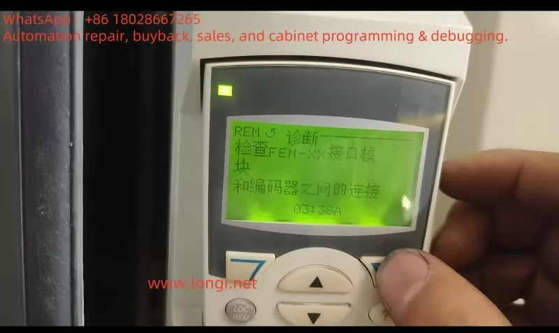
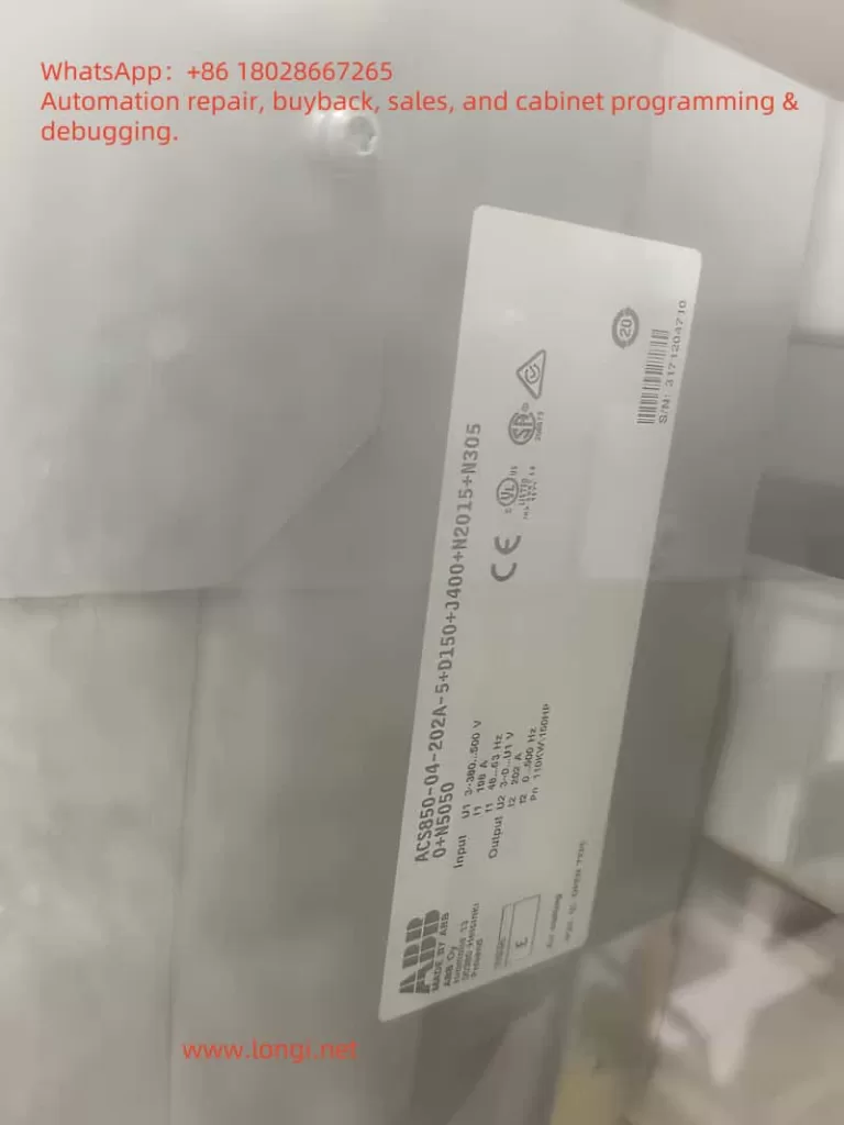
The ABB ACS850 inverter is a widely used AC motor control device in the industrial sector, renowned for its high flexibility and reliability. However, when the inverter displays the fault code “03:58A”, it may indicate an issue with the Encoder Interface Module (FEN-XX) or the communication between the encoder and the inverter, leading to equipment shutdown. This document provides detailed instructions on how to diagnose and repair this fault on-site, including checking physical connections, testing hardware, adjusting parameters to support encoder-less operation, as well as maintenance and preventive measures. By following a systematic approach, technicians can quickly locate the problem and restore equipment operation.
Meaning of Fault Code “03:58A”
The fault code “03:58A” is not explicitly listed in the standard ACS850 fault code list (as per the ABB ACS850 manual) and may be a specific error code for the FEN-XX module or a non-standard display on the user interface. Based on user descriptions, this fault is related to the FEN-XX module and encoder connection. Possible causes include:
- Physical Connection Issues: Loose encoder cables, damaged cables, or poor connector contact.
- Hardware Failure: Damage to the FEN-XX module, encoder, or inverter communication interface.
- Parameter Configuration Errors: Mismatch between the encoder module configuration expected by the inverter and the actual hardware.
- Power Supply Problems: Unstable supply voltage affecting the communication channel.
Understanding these potential causes helps in formulating an effective diagnostic strategy.
On-site Diagnostic Steps
When the ACS850 displays the fault code “03:58A”, technicians should follow these steps for diagnosis:
1. Check Physical Connections
Steps:
- Confirm that the FEN-XX module (e.g., FEN-01, FEN-11, or FEN-21) is firmly inserted into slot 1 or slot 2 of the inverter.
- Inspect the encoder cable for breaks, wear, or corrosion.
- Ensure that connectors are not loose or have poor contact.
Tools: Screwdriver, multimeter (for testing cable continuity).
Precautions: Disconnect power and follow lockout/tagout procedures to ensure safety.
2. Check for Hardware Damage
Steps:
- Inspect the inverter, FEN-XX module, and encoder for signs of burning, capacitor bulging, or other electrical stress.
- If possible, test with a spare, known-good module or encoder.
Tip: Record any abnormalities (such as burn marks or odors) for further analysis.
3. Verify Parameter Settings
Steps:
- 90.01 Enc Module Sel: Should be set to 0 (None) if no encoder is used.
- 90.02 Encoder 2 Sel: Set to 0 (None) if no second encoder is present.
- 90.05 Enc Cable Fault: Set to 0 (No) to avoid fault alarms when no encoder is used.
Access the parameter menu using the control panel or DriveStudio software.
Check parameters related to the encoder module:
- Confirm that the control mode (parameter 40.01) matches the current hardware configuration.
- Reference: ABB ACS850 firmware manual.
4. Test the Module and Inverter
Steps:
- If the fault disappears, the issue may be with the module or its connection.
- If the fault persists, check the inverter’s communication interface.
Remove the FEN-XX module and attempt to run the inverter:
- Replace the current module with a known-good FEN-XX module and observe if the fault is resolved.
Note: Record the results of each test to trace the source of the problem.
5. Check Power Supply Stability
Steps:
- Use a multimeter to measure the supply voltage to the inverter and module, ensuring it meets specifications (e.g., 230V or 400V).
- Check for voltage fluctuations or interruptions that may affect communication.
Recommendation: Use an uninterruptible power supply (UPS) or voltage stabilizer to improve stability.
Parameter Adjustment for Encoder-less Operation
If the application does not require an encoder, the ACS850 can operate using sensorless vector control or V/f control. These modes rely on internal algorithms to estimate motor speed without encoder feedback, suitable for applications with lower precision requirements. Below are the key parameters to adjust:
| Parameter Number | Parameter Name | Recommended Setting | Description |
|---|---|---|---|
| 90.01 Enc Module Sel | Encoder Module Selection | 0 (None) | Disable encoder module |
| 90.02 Encoder 2 Sel | Secondary Encoder Selection | 0 (None) | Disable second encoder |
| 90.05 Enc Cable Fault | Encoder Cable Fault | 0 (No) | Avoid fault alarms when no encoder is used |
| 19.02 Speed to Sel | Speed Source Selection | 0 or 2 (Estimated) | Use internal speed estimation |
| 40.01 Control Mode | Control Mode Selection | 1 (V/f control) or 3 (Sensorless vector control) | Select appropriate control mode |
| 33.02 Superv1 Act | Supervision 1 Actual Value | Speed rpm | Use estimated speed value instead of encoder value |
Operational Notes:
- V/f Control (Parameter 40.01 = 1): Suitable for applications with low speed precision requirements.
- Sensorless Vector Control (Parameter 40.01 = 3, depending on firmware version): Provides better low-speed performance but requires correct setup of motor parameters (such as rated voltage, current, frequency).
- Switching to encoder-less mode may reduce control precision at low speeds, which should be evaluated based on application requirements.
Specific parameter values may vary by firmware version; it is recommended to refer to the ABB ACS850 firmware manual.
Determining the Fault Source
To accurately determine whether the fault originates from the inverter, encoder, or interface module, perform the following tests:
1. Inverter Test
Method: Remove all option modules and attempt to run the inverter.
Results:
- If the fault code “03:58A” disappears, the issue may be with the FEN-XX module or its connection.
- If the fault persists, there may be an issue with the inverter’s communication interface.
2. Module Test
Method: Replace the current FEN-XX module with a known-good module and restart the inverter.
Results:
- If the fault disappears, the original module may be damaged.
- If the fault persists, check the cable or inverter.
3. Cable Test
Method: Use a multimeter or cable tester to check the continuity and correct wiring of the encoder cable and module connection cable.
Results: Replace the cable if a break or short circuit is found.
4. Diagnostic Parameter Check
Method: Check parameter group 08 (Alarms & Faults) for any other communication errors or hardware fault indications.
Tool: Control panel or DriveStudio software.
Maintenance and Replacement
Based on the diagnostic results, take the following maintenance measures:
1. Repair Loose Connections
- Refasten loose cables or connectors to ensure good contact.
- Clean connectors to remove dust or corrosion.
2. Replace Damaged Cables
- Replace damaged cables with shielded cables of the same specifications to reduce electromagnetic interference.
- Ensure cable length and wiring comply with ABB recommended standards.
3. Replace Faulty Modules
- If the FEN-XX module or encoder is damaged, replace it with a compatible model (e.g., FEN-01, FEN-11, or FEN-21).
- After replacement, reconfigure relevant parameters (such as 90.01, 90.02).
4. Inverter Repair
- If the issue is with the inverter itself, contact ABB technical support for repair or replacement.
- Do not attempt to repair internal components of the inverter unless you are a certified technician.
Safety Precautions
- Power Disconnection: Disconnect power and wait for capacitors to discharge (usually 5 minutes) before touching any internal components.
- Protective Gear: Wear insulating gloves and safety glasses.
- Lockout/Tagout: Follow lockout/tagout procedures to prevent accidental startup.
- Grounding Check: Ensure the equipment is properly grounded to reduce electromagnetic interference.
Preventive Measures
To prevent similar faults from recurring, it is recommended to:
- Regular Maintenance: Inspect cables, connectors, and modules every 6 months.
- Firmware Updates: Keep the inverter firmware up to date to fix known issues.
- Parameter Backup: Use DriveStudio to back up parameter settings for quick restoration.
- Environmental Control: Ensure the inverter operates in an environment that meets temperature, humidity, and cleanliness requirements (refer to the ABB ACS850 hardware manual).
Conclusion
The ACS850 inverter fault code “03:58A” may be related to the Encoder Interface Module (FEN-XX) or encoder communication issues. By checking physical connections, testing hardware, adjusting parameters for encoder-less operation, technicians can quickly resolve the problem. Determining the fault source (inverter, encoder, or module) is a critical step, requiring a combination of physical inspection and parameter analysis. If the issue is complex, contacting technical support is advisable. Regular maintenance and proper configuration can significantly reduce the occurrence of such faults, ensuring reliable operation of industrial systems.