
Introduction
The ABB ACS800 series inverters are widely used in industrial control applications, providing reliable AC drive solutions for various conditions, including induction and synchronous motor control. Known for their high power density, advanced harmonic suppression, extensive programmability, and modular design, the ACS800 series excels in industries such as process manufacturing, metal processing, mining, cement production, power generation, chemicals, oil and gas, and even special applications like offshore supply vessels. However, in practical use, the ACS800 inverters may encounter faults, with fault code 7510 being a common communication-related issue. This article provides a comprehensive exploration of fault code 7510, including its meaning, potential causes, diagnostic steps, solutions, and preventive measures to guide users effectively.
Overview of the ACS800 Inverter
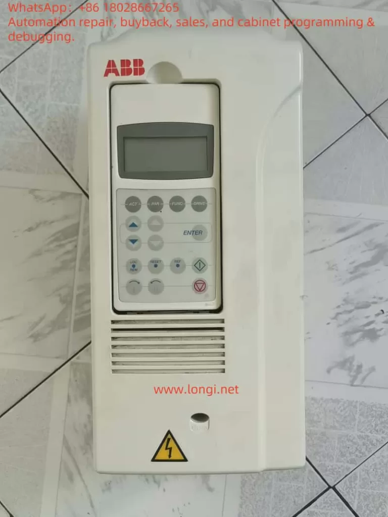
The ACS800 series from ABB is a high-performance AC drive designed to meet the needs of a wide range of applications, from small equipment to large industrial systems. Its key features include:
- High Power Density: Delivers high output power in a compact form, ideal for space-constrained environments.
- Harmonic Suppression: Utilizes advanced technology to reduce harmonic interference, enhancing power quality.
- Extensive Programmability: Offers a rich set of parameters and control options for customized applications.
- Modular Design: Facilitates easy installation, maintenance, and upgrades, reducing operational costs.
The ACS800 inverter is commonly deployed in scenarios requiring precise motor control, such as assembly lines, pump stations, and fan systems. However, communication issues remain a potential challenge, with fault code 7510 being a notable example.
Meaning of Fault Code 7510
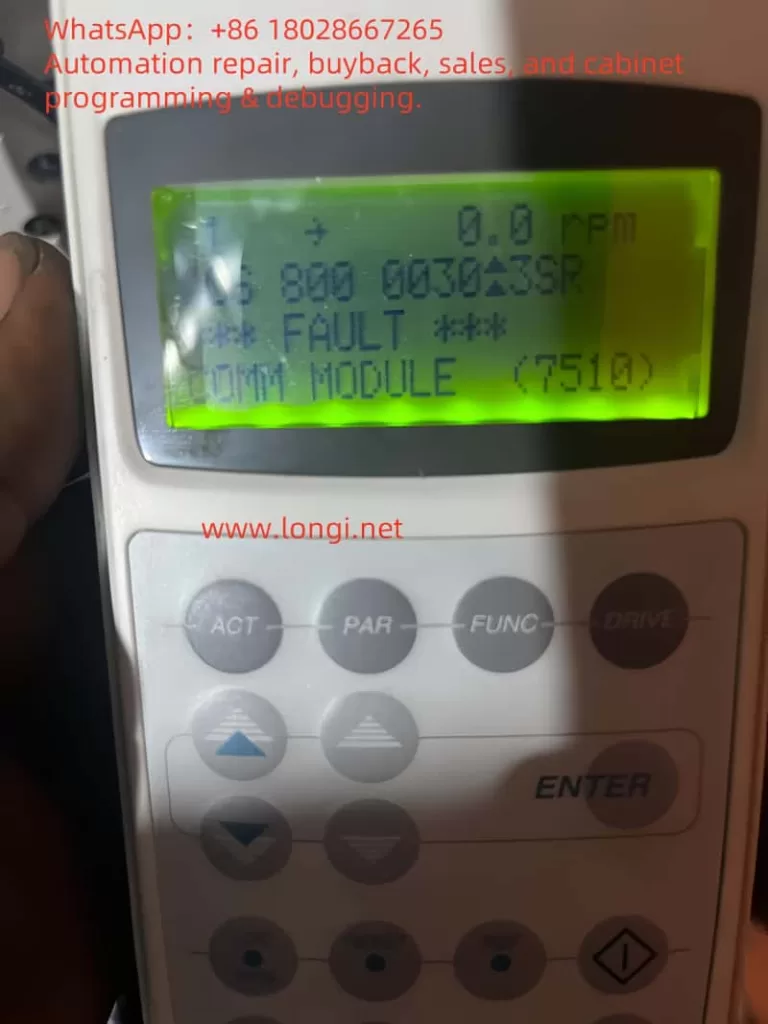
In the ACS800 inverter, fault code 7510 typically indicates a “COMM MODULE FAULT.” This fault suggests a periodic loss of communication between the inverter and its main controller, such as a PLC or DCS. Such a disruption can prevent the inverter from receiving control commands or transmitting status updates, severely affecting system operation.
According to official documentation, the 7510 fault is associated with the communication module and is often triggered by programmable fault functions (parameters 30.18 and 30.19). The communication module serves as the bridge between the inverter and external control systems, handling data exchange and synchronization. Any malfunction in this module can compromise the entire system’s performance.
Analysis of Potential Causes
Fault code 7510 can stem from various factors. Below is a detailed analysis of common causes:
| Category | Specific Issue | Description |
|---|---|---|
| Communication Connection Issues | Damaged or loose cables | Physical damage, aging, or poor connections can interrupt signals. |
| Excessive cable length | Cable length exceeding protocol specifications (e.g., Modbus max of 1200 meters) may cause signal loss. | |
| Poor connector contact | Improperly installed or corroded connectors. | |
| Parameter Setting Errors | Mismatched communication protocol | Inconsistent settings (e.g., baud rate, data bits, stop bits) with the main controller. |
| Address conflicts | Inverter address clashes with other devices in the system. | |
| Improper timeout settings | Too short a timeout period may trigger faults under network load. | |
| Fieldbus Configuration Errors | Incorrect configuration file | Errors in the fieldbus configuration file (e.g., GSD file). |
| Termination resistor issues | Missing or incorrect termination resistors causing signal reflection. | |
| Fieldbus power problems | Unstable or interrupted fieldbus power supply. | |
| Main Controller Issues | Configuration errors | Incorrect main controller setup unable to recognize the inverter. |
| Software incompatibility | Mismatched software versions between the controller and inverter. | |
| Hardware failure | Damaged controller hardware affecting data transmission. | |
| Inverter Internal Faults | Communication module failure | Hardware damage or aging of the communication module. |
| Firmware issues | Incompatible or buggy firmware versions. |
Diagnostic Steps
When the ACS800 inverter displays fault code 7510, follow these systematic diagnostic steps to identify the root cause:
- Inspect Communication Cables:
- Check for physical damage such as cuts or wear.
- Ensure all connectors are secure and free from corrosion or dust.
- Verify that cable length complies with protocol specifications.
- Verify Parameter Settings:
- Access the inverter’s parameter menu and review group 51 (COMM MODULE DATA for fieldbus adapter) or group 52 (STANDARD MODBUS for Modbus links).
- Confirm that baud rate, data bits, stop bits, and other settings match the main controller.
- Check fault function parameters (e.g., 30.18, 30.19) for correct configuration.
- Check Fieldbus Status:
- For fieldbus systems (e.g., Profibus, DeviceNet, or ControlNet), refer to the relevant fieldbus adapter manual.
- Use diagnostic tools to monitor communication status and detect packet loss or errors.
- Ensure termination resistors are correctly set (typically 120 ohms) and power supply is stable.
- Restart the System:
- Power off the inverter and main controller, wait a few minutes, then restart.
- Observe if the fault clears, ruling out temporary issues.
- Inspect the Main Controller:
- Confirm the main controller is properly configured to communicate with the inverter.
- Review controller logs for communication-related errors.
- Ensure software compatibility between the controller and inverter.
- Replace the Communication Module:
- If all else fails, the communication module may be faulty.
- Before replacement, ensure compatibility with the inverter’s firmware and involve a qualified technician.
Solutions
Based on the diagnosis, implement the following targeted solutions:
- Fix Communication Connections:
- Replace damaged cables with those meeting specifications.
- Re-secure loose connectors and clean any corrosion or debris.
- Correct Parameter Settings:
- Adjust group 51 or 52 parameters to align with the main controller’s configuration.
- Increase communication timeout settings (e.g., parameters 30.18 or 30.19) to accommodate network load.
- Reconfigure the Fieldbus:
- Verify and correct the fieldbus configuration file.
- Set proper termination resistors and check for power stability.
- Eliminate interference from other devices.
- Address Main Controller Issues:
- Update the main controller software to the latest version for compatibility.
- Correct configuration errors such as address or protocol settings.
- Replace damaged controller hardware if necessary.
- Replace the Communication Module:
- Contact ABB technical support or a professional to replace a defective module.
- Reconfigure parameters and test communication post-replacement.
Case Studies
Here are two real-world examples illustrating the diagnosis and resolution of 7510 faults:
- Case 1: Interference in a ControlNet System
In a ControlNet-based system, the ACS800 inverter intermittently triggered a 7510 fault. Investigation revealed that another device was sending erroneous data packets, disrupting communication. Isolating the device and rescheduling network connections resolved the issue. - Case 2: Incorrect Parameter Settings
In a Modbus system, a 7510 fault occurred due to an excessively short timeout setting, causing failures under network load. Adjusting parameter 30.18 to extend the timeout restored normal communication.
These cases highlight the need to consider hardware, software, and network factors when resolving 7510 faults.
Preventive Measures
To minimize the occurrence of 7510 faults, users can adopt the following preventive strategies:
- Regular Connection Checks:
- Inspect communication cables and connectors monthly for damage or looseness.
- Clean connectors to prevent dust or corrosion buildup.
- Backup Parameter Settings:
- Regularly save inverter and controller parameter settings in a secure location.
- Maintain backups before equipment replacement or firmware updates.
- Keep Systems Updated:
- Periodically check for the latest inverter firmware and controller software.
- Ensure all component versions are compatible.
- Train Operators:
- Provide training on inverter operation, parameter settings, and basic troubleshooting.
- Familiarize staff with relevant manual sections.
- Implement Monitoring Systems:
- Use software to monitor communication status and fault alerts in real time.
- Set up automatic notifications for prompt response to issues.
These measures can significantly enhance system reliability and reduce downtime.
Conclusion
Fault code 7510 in the ACS800 inverter is a common communication module issue, potentially caused by cable problems, parameter errors, fieldbus misconfiguration, or hardware failures. Through systematic diagnostic steps—such as cable inspection, parameter verification, and fieldbus reconfiguration—along with targeted solutions like repairs, adjustments, or module replacement, users can effectively resolve the fault. Coupled with preventive actions like regular maintenance, parameter backups, and operator training, these strategies ensure long-term system stability. This article aims to provide clear, practical guidance for addressing ACS800 inverter 7510 faults.