
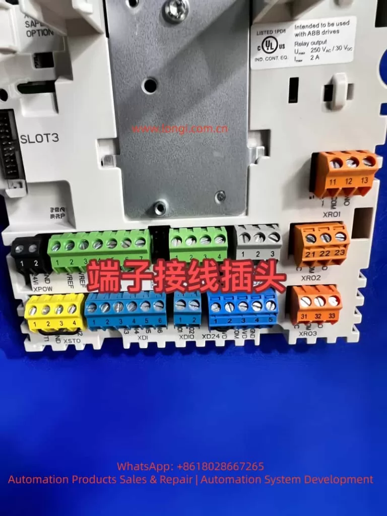
In an ABB ACS880 drive, allocating digital inputs (DIs) and outputs (DOs) requires configuring parameters to connect specific drive signals or functions to the available I/O terminals. This is typically accomplished through the drive’s control panel, the Drive Composer PC tool, or fieldbus communication. The ACS880 features six standard digital inputs (DI1–DI6), one digital interlock input (DIIL), and two digital input/outputs (DIO1–DIO2) that can be configured as either inputs or outputs. Additional I/O can be added via expansion modules such as the FIO-01 or FDIO-01.
The following is a step-by-step guide compiled based on the ACS880 main control program firmware manual. Before making any changes, be sure to refer to the complete hardware and firmware manuals, safety precautions, and wiring diagrams specific to your drive variant. Ensure that the drive is powered off during wiring and follow all safety instructions.
Prerequisites
- Confirm the drive’s I/O terminals: Standard I/O is located on the control unit (e.g., XDI for DIs, XDIO for DIOs, and XRO for relay outputs, which are typically used as DOs).
- Back up existing parameters before making modifications.
- Use parameter group 96 (System) to select an appropriate application macro based on predefined settings (e.g., the Factory macro sets DI1 as the start/stop command by default).
Steps for Allocating Digital Inputs (DIs)
Digital inputs are used to control functions such as start/stop, direction, fault reset, or external events. Allocation means selecting a DI as the source for a specific drive function within the relevant parameter group.
Access Parameters
Use the drive’s control panel (Menu > Parameters) or Drive Composer to navigate to the parameter groups.
Monitor DI Status (Optional, for Troubleshooting)
- Parameter 10.01: Displays the real-time status of DIs (bit-encoded: bit 0 = DIIL, bit 1 = DI1, etc.).
- Parameter 10.02: Displays the delayed status after applying filters/delays.
Adjust Filtering
Set Parameter 10.51 DI Filter Time (default: 10 ms, range: 0.3–100 ms) to eliminate signal jitter.
Allocate Functions to DIs
Navigate to the parameter group for the desired function and select a DI as the source.
Examples:
- Start/Stop Command (Group 20 Start/Stop/Direction):
- 20.01 Ext1 Command: Set to “In1 Start; In2 Direction” and assign DI1 to 20.02 Ext1 Start Trigger Source and DI2 to 20.07 Ext1 Direction Source.
- Jogging:
- 20.26 Jog 1 Start Source = Selected DI (e.g., DI3).
- Speed Reference Selection (Group 22):
- 22.87 Constant Speed Select 1 = Selected DI (e.g., DI4 to activate constant speed).
- Fault Reset (Group 31 Fault Functions):
- 31.11 Fault Reset Source = Selected DI (e.g., DI5).
- External Events (Group 31):
- 31.01 External Event 1 Source = Selected DI (e.g., DI6 to trigger warnings/faults).
- PID Control (Group 40 Process PID Settings 1):
- 40.57 PID Activation Source = Selected DI.
- Motor Thermal Protection (Group 35):
- Use DI6 as a PTC input: Set 35.11 Temperature 1 Source = “DI6 (inv)” for inverted logic.
- For DIO as Input:
- Set 11.02 DIO Delay Status for monitoring and allocate functions as with DIs (e.g., DIO1 can be used as a frequency input via 11.38 Frequency Input Scaling).
Set Delays (if required)
For each DI, use parameters 10.05–10.16 (e.g., 10.05 DI1 On Delay = 0.0–3000.0 s, default: 0.0 s) to define activation/deactivation delays.
Force DIs for Testing
- 10.03 DI Force Select: Choose the DI bit to override.
- 10.04 DI Force Data: Set the forced value (e.g., force DI1 high for simulation).
Steps for Allocating Digital Outputs (DOs)
Digital outputs (including relay outputs RO, which are commonly used as DOs, and DIO configured as outputs) are used to indicate drive states such as running, fault, or ready. Allocation means selecting a drive signal as the source for an output.
Access Parameters
Same as above.
Configure Relay Outputs (ROs, Commonly Used as DOs)
Group 10 Standard DI, RO:
- 10.24 RO1 Source: Select a signal (e.g., “Ready to Run” = bit pointer 01.02 bit 2).
- 10.27 RO2 Source, 10.30 RO3 Source: Similar to RO1.
- Default values: RO1 = Ready to Run, RO2 = Running, RO3 = Fault (-1, inverted).
- Delays: 10.25 RO1 On Delay (0.0–3000.0 s), 10.26 RO1 Off Delay.
Configure DIOs as Outputs
Group 11 Standard DIO, FI, FO:
- 11.05 DIO1 Function: Set to “Output” (default: Input).
- 11.06 DIO1 Output Source: Select a signal (e.g., “Running” = 01.06 bit 1).
- Similarly, for DIO2: 11.08 DIO2 Function = “Output”, 11.09 DIO2 Output Source.
- Delays: 11.07 DIO1 On Delay, 11.10 DIO1 Off Delay (same for DIO2).
- For frequency output: Use DIO2 as FO via 11.42 Frequency Output Source (e.g., actual speed).
Common Allocation Examples
- Route “Fault” to RO3: Set 10.30 RO3 Source = “Fault (-1)” for inverted logic (output activated when no fault is present).
- Route “Setpoint Reached” to DIO1: 11.06 = “Setpoint Reached” (06.11 bit 8).
- For brake control (Group 44): 44.18 Brake Open Request Source = Selected DO.
Additional Notes
- Logic Inversion: Many parameters support inverted logic (e.g., “DI1 (inv)” indicates low-level active).
- Expansion Modules: For more I/O, use groups 14–16 (e.g., 14.03 Module 1 Type = FIO-11, then configure 14.11–14.16 to add additional DIs).
- Application Macros: Start with a macro (96.04 Macro Selection) for pre-allocated I/O and then customize.
- Safety and Testing: After allocation, test in a safe environment. If available, use simulation mode (95.20 HW Option Word 1, bit 14).
- Frequency I/O: DIO1 can be a frequency input (11.38 Frequency Input Scaling), and DIO2 can be an output (11.45 Frequency Output Scaling).
- If issues arise, check diagnostics (Group 04 Warnings/Faults) or consult ABB support.
- For detailed wiring information, refer to the ACS880 hardware manual.