
Introduction
In the field of industrial automation, Variable Frequency Drives (VFDs) are essential for controlling motor speed and torque. The Shihlin SS2 series inverter is widely recognized for its efficiency and reliability across various industrial applications. However, like any electronic device, it may encounter faults, one of which is the “ou0” fault—a common issue that can lead to downtime and affect productivity. This article provides an in-depth analysis of the “ou0” fault, its causes, and detailed solutions to help users restore normal operation swiftly.
What Is the “ou0” Fault?
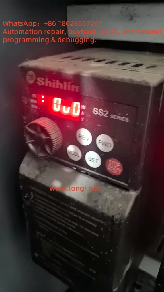
The “ou0” fault code typically indicates that the inverter has detected an excessively high DC bus voltage, a condition known as overvoltage. The DC bus is a critical component in the inverter that converts AC input into DC before inversion. When the DC bus voltage exceeds the safety threshold, the inverter triggers a protective mechanism, displaying “ou0” and halting operation to prevent damage to internal components like the IGBT module. On the Shihlin SS2 inverter’s control panel, “ou0” is usually shown in red, accompanied by an abnormal status of the operation indicator light.
Common Causes of the “ou0” Fault
Overvoltage faults can stem from multiple factors, with the following being the most prevalent:
- High Input Voltage
If the AC input voltage exceeds the inverter’s rated range (typically 380V ±15%), the DC bus voltage rises accordingly. Grid fluctuations, poor power quality, or external disturbances like lightning strikes can contribute to this issue. - Regenerative Energy Feedback
During motor deceleration, especially with high-inertia loads (e.g., CNC machines or heavy machinery), the motor can act as a generator, feeding energy back to the inverter. If the deceleration time is too short or there is no mechanism to dissipate this energy, the DC bus voltage spikes. - Component Aging or Failure
DC bus capacitors play a vital role in absorbing and stabilizing voltage. Aging or damaged capacitors may fail to perform, leading to voltage fluctuations. Additionally, faults in the rectifier or inverter modules can also cause overvoltage. - Improper Parameter Settings
A deceleration time set too short is a frequent misconfiguration, causing regenerative energy to accumulate rapidly. Other parameters, such as voltage regulation settings, may also impact voltage stability. - External Factors
- Excessively long cables or degraded insulation can introduce voltage interference or leakage.
- Environmental conditions like high temperatures or dust accumulation may affect the inverter’s cooling and performance.
Diagnosing the “ou0” Fault
To accurately identify the cause of the “ou0” fault, a systematic diagnostic approach is recommended:
- Check Input Voltage
Use a multimeter to measure the three-phase input voltage of the inverter, ensuring it falls within the Shihlin SS2 series’ rated range (typically 380V ±15%). If the voltage is too high or fluctuates significantly, investigate grid stability or external interference. - Review Deceleration Time Settings
Access the inverter’s parameter settings through the control panel and check the deceleration time parameter (possibly P.02, as per the manual). If the deceleration time is too short (e.g., 2 seconds), consider extending it to 5 seconds or more to reduce regenerative energy buildup. - Inspect DC Bus Capacitors
If possible, use a capacitance tester to measure the DC bus capacitors’ capacitance and equivalent series resistance (ESR). Aging capacitors may show reduced capacitance or physical damage (e.g., bulging or leakage). Replace them if necessary. - Evaluate Load Characteristics
Determine if the load is high-inertia (e.g., heavy machinery or fans). High-inertia loads generate significant regenerative energy during deceleration, potentially requiring additional braking equipment. - Inspect Cables and Grounding
Ensure the output cable length does not exceed the recommended limit (typically 50 meters) and check the cable insulation for integrity. Verify that the inverter is properly grounded to avoid electrical noise or static interference. - Use Diagnostic Tools
If the inverter supports communication features, connect diagnostic software to view detailed fault logs. Record the operating condition during the fault (e.g., acceleration, deceleration, or constant speed) for further analysis.
Solutions
Based on the diagnosis, the following measures can resolve the “ou0” fault:
- Adjust Deceleration Time
Extending the deceleration time is a simple and effective way to address regenerative energy issues. Access the parameter settings via the control panel and adjust the deceleration time (e.g., P.02) from a short duration (like 2 seconds) to 5 seconds or longer, depending on the load characteristics. - Install a Braking System
For high-inertia loads, installing a braking resistor and braking unit is highly recommended. The braking resistor dissipates excess regenerative energy as heat, preventing the DC bus voltage from rising beyond the protection threshold. Ensure the resistor matches the inverter model, as specified in the Shihlin SS2 manual. - Stabilize Input Voltage
If the grid voltage is unstable, consider installing a voltage regulator or reactive power compensation device. A line reactor can also help filter high-order harmonics, improving power quality. - Replace Faulty Components
If the capacitors or other internal components are damaged, they should be replaced by a qualified technician. Ensure the power is disconnected and safety protocols are followed during replacement. - Optimize Environmental Conditions
Ensure the inverter is installed in a well-ventilated, temperature-controlled environment. Regularly clean the heat sink and fan to prevent dust buildup that could impair cooling. - Reset Parameters
If parameter settings may be incorrect, reset the inverter to factory defaults (often by holding the “STOP/RESET” key while powering on, as per the manual). Reconfigure the necessary parameters afterward.
Preventive Measures
To prevent the recurrence of the “ou0” fault, consider the following:
- Regular Maintenance: Inspect the inverter’s capacitors, connectors, and cooling system every 6-12 months to ensure optimal condition.
- Monitor Power Quality: Use a power quality analyzer to periodically check the input voltage stability and address potential issues early.
- Optimize Parameter Settings: Adjust acceleration and deceleration times to match the load characteristics, ensuring compatibility with the application.
- Install Protective Equipment: In lightning-prone areas, install surge protection devices to safeguard the inverter from transient overvoltage.
Case Study
In a manufacturing plant, a Shihlin SS2 inverter controlling a CNC machine frequently reported the “ou0” fault during rapid deceleration. Technicians first measured the input voltage, confirming it was within 380V ±10%, ruling out power supply issues. They then reviewed the parameters and found the deceleration time set to 2 seconds, which was too short. After extending it to 5 seconds, the fault ceased. To further enhance reliability, the plant installed a braking resistor, effectively managing the regenerative energy from the high-inertia load. This case highlights the importance of proper parameter adjustments and hardware upgrades in resolving the “ou0” fault.
Conclusion
The “ou0” fault in the Shihlin SS2 inverter is typically an overvoltage issue caused by factors like input voltage anomalies, regenerative energy buildup, or component failure. Through systematic diagnosis (e.g., checking voltage, adjusting parameters, installing braking systems), users can effectively address the issue. Regular maintenance and optimized settings are key to preventing future faults. If the problem persists, professional technical support is advised to ensure safe and reliable operation.
Common Overvoltage Fault Codes and Solutions
Below is a summary of typical overvoltage faults in inverters for reference:
| Fault Code | Description | Possible Causes | Solutions |
|---|---|---|---|
| OV1 | Overvoltage during acceleration | High input voltage, short acceleration time | Extend acceleration time, check input voltage |
| OV2 | Overvoltage at constant speed | Regenerative energy buildup, capacitor failure | Check capacitors, install braking unit |
| OV3 | Overvoltage during deceleration | Short deceleration time, high-inertia load | Extend deceleration time, install braking resistor |
| OU | General overvoltage alarm | High DC bus voltage, external interference | Check voltage, address cable issues, install lightning protection |
Note: The Shihlin SS2 may use “ou0” to denote overvoltage, which should be confirmed with the specific manual.