
I. Preface
In the automated assembly industry, electric screwdrivers have become indispensable end-effector tools in electronic manufacturing, automotive assembly, and precision assembly scenarios. Among them, the DAT ED series electric screwdriver system with intelligent control functions features programmable torque control, tightening curve monitoring, error determination and feedback, and the ability to operate in conjunction with relays/PLCs, enabling fully automatic cycle control and quality traceability.
Many maintenance personnel, when coming into contact with this model of controller, may misunderstand the relationship between the 48V main power supply and the 24V I/O signals, leading to an inability to start the device or even causing damage to the controller due to incorrect wiring. Based on documentation, on-site cases, and practical maintenance experience, this article provides a systematic explanation from multiple perspectives, including structural principles, signal interpretations, fault analysis, wiring methods, and control start-up modes, offering a comprehensive and actionable guidance document for users and maintenance technicians.

Core Objectives
- Explain why the electric screwdriver uses a 48V power supply but the I/O signals can only operate at 24V.
- Analyze the logical relationships among signals such as Ready, System OK, Start, and OK/NG.
- Identify the real causes of the electric screwdriver’s failure to start and provide troubleshooting methods.
- Provide correct wiring and PLC control methods, as well as the dangerous consequences of incorrect wiring.
- Develop a mature and replicable fault diagnosis process based on actual maintenance cases.
II. Structure and Interface Definitions of the ED Electric Screwdriver System
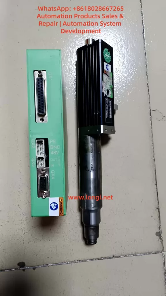
The DAT ED control system mainly consists of a controller (Interface 330E / 330 OS Advanced), an electric screwdriver body, motor cables, a power supply, and network communication interfaces. The controller undertakes three core tasks: driving the motor (powered by 48V), analyzing tightening strategies and torque detection, and communicating with external systems for I/O interactions and status exchanges.
Main Interface Functions
| Interface | Name | Functional Description |
|---|---|---|
| GX1 | I/O Signal Terminal | Input for start-up and program selection; output for Ready, OK/NG, and System OK signals |
| GX2 | 48V Power Interface | Core input for motor and system power supply |
| GX3 | Emergency Stop Interface | Normally closed during operation; disconnecting locks the controller |
| GX4 | Motor Output Interface | Connects to the electric screwdriver body for power transmission |
| GX5 | USB Interface | Used for firmware recovery/maintenance |
| GX6 | Ethernet | Enables parameter and data access via a web page |
Among these, GX1 and GX2 are the key interfaces that are often misunderstood. The controller’s internal logic is processed by an MCU, but the motor, being a high-power load, must be powered by 48V.
Voltage Allocation
| Power Supply | Purpose | Voltage | Characteristics |
|---|---|---|---|
| Main Power Supply | Controller + Motor Power Drive | 48V | High power, drives loads |
| I/O Signal Power Supply | Signal Input/Output Logic | 24V | Only for signal transmission, with extremely low current |
Note: The 48V power supply cannot be directly fed into the I/O terminals. The Start pin cannot be connected to 48V; it can only be triggered by a 24V high level.
III. Detailed Explanation of I/O Signal Logic
The I/O terminals adopt a PNP architecture, with signals being effective at a 24V high level.
Input Signals (External Control Lights/PLC Input Control Pins)
| Pin | Name | Function | Triggering Method |
|---|---|---|---|
| 1 | Start | Initiates the tightening process | Apply 24V = Start |
| 2-5 | Program Number Selection | Sets the program using an 8421 combination code | 1 = Pin 2 connected to 24V, 2 = Pin 3 connected to 24V, etc. |
Output Signals (Reporting the Electric Screwdriver’s Operating Status Externally)
| Pin | Signal | Meaning | Normal Output |
|---|---|---|---|
| 14 | System OK | Indicates that the controller’s self-health check has passed | 24V |
| 15 | Ready | Indicates that the system is ready for start-up | 24V |
| 16/17 | OK / NG | Determines the result of the current tightening operation | Outputs 24V after action |
Start-up Conditions: The tightening action can only be triggered by the Start signal when the controller has completed its system self-check and the Ready signal is at a high level. That is:
- 48V power supply is normal
- The emergency stop interface (GX3) is closed
- The motor cables are properly connected
- The program is valid
- System OK = 24V
- Ready = 24V
At this point, applying 24V to the Start pin → The electric screwdriver starts rotating.

IV. Common Fault Phenomena and Cause Analysis
In actual maintenance cases, over 80% of the problems stem from the following categories.
Controller Has No Output and No Ready Signal
Manifestations:
- No voltage measured between Pin 14 or 15 and 0V
- The web page can be accessed, but programs cannot be executed
- Error messages such as “Screwdriver not found” / “ERROR SCREWDRIVER 0” are reported
Troubleshooting:
| Inspection Item | Handling Suggestion |
|---|---|
| Stability of the 48V power supply | Must provide a current output of ≥2-5A |
| Whether the emergency stop interface is short-circuited | GX3 must be bridged between pins 1 and 2 |
| Whether the motor cable plug is fully inserted | Looseness can lead to the electric screwdriver not being detected |
| Damage to the control board | The controller needs to be replaced |
If the controller is damaged, the Ready signal will never appear, and it is inevitable that the I/O output terminals will remain at a low level.
No Response to Start-up But Ready Signal Is Lit
This situation often results from incorrect user wiring methods.
Common Incorrect Wiring:
- Grounding the Start pin (Pin 1) to trigger → Incorrect
- Connecting Pin 1 to 48V for start-up → Seriously incorrect, may burn out the I/O chip
Correct Method:
- Pin 1 ← 24V positive (high level effective) → Correct
V. Correct Wiring Examples (The Most Critical Implementation Part)
Power Connection
- 48V+ → GX2 +
- 48V- → GX2 –
I/O Signal Power Supply (Providing 24V)
- 24V+ → GX1 Pin 24/25
- 24V- → GX1 Pin 12/13
Emergency Stop Handling
- GX3 Pin 1-2 must be short-circuited
Start-up Test Method (Without PLC)
When the Ready signal is at 24V:
- Use a wire to short-circuit Pin 1 (Start) and Pin 24 (24V+) → The electric screwdriver starts working immediately
Typical PLC Wiring Structure Diagram
- PLC Output (Q0.0 PNP output) → Pin 1 (Start)
- PLC Common Terminal COM → Pin 12/13 (0V)
- Ready/System OK signals → PLC input terminals I0.0/I0.1 for reading
This meets the requirements for industrial automation linkage.
VI. Analysis and Summary of Actual Maintenance Cases
Maintenance Report:
- Device Fault Phenomenon: The computer can connect and display the interface, but the Ready signal is missing, and an error message “ERROR SCREWDRIVER 0” (screwdriver not found) is reported.
- Disassembly Inspection: The controller is damaged → No repair value.
- Recommendation: Replace the controller.
Based on signal logic analysis, this hardware has lost its execution channel, with abnormal output drive transistors or an internal MCU, preventing the Ready/System OK signals from being pulled high. This is a terminal hardware fault, and replacing the controller is the only solution.
Damage Causes:
| Possible Inducement | Probability |
|---|---|
| Incorrectly connecting 48V to the GX1 signal pins | Extremely high |
| I/O line insertion/removal while powered, causing breakdown | Medium |
| EMC environmental interference and current surges | Medium |
| Motor short-circuit or overload | Low |
| Board card aging | Common but with a slow impact |
Proper training and documentation guidance are of utmost importance.
VII. Knowledge Structure Summary
- 48V is the power source, and 24V is the signal source; they cannot be mixed.
- The Start signal must be triggered by a 24V high level, not by grounding or 48V.
- The Ready/System OK outputs are used to judge the controller’s status.
- The emergency stop port must be bridged; otherwise, the system will never be ready.
- If there is no Ready signal, the device cannot start. First, check the power supply and motor connections, and then assess the controller’s health.
- Maintenance thinking must first distinguish between logical faults and hardware damage.
VIII. Conclusion
For automated assembly equipment, although the electric screwdriver controller is small in size, it undertakes the critical task of executing key processes. Understanding its power drive system and I/O signal triggering mechanism is a fundamental skill for equipment engineers, automation debuggers, and maintenance personnel.
Through the systematic analysis in this article, we have not only clarified the division of labor between 48V and 24V but also established a complete technical route from wiring and start-up to fault handling, making the debugging process rule-based and providing a more evidence-based basis for maintenance judgments.
As the industry continues to advance towards intelligent manufacturing, mastering the underlying principles and signal characteristics of equipment is no longer just a maintenance capability but an integral part of the competitiveness of engineering personnel.