
Introduction
In the realm of modern industrial automation, servo drives, as the core components of precision control systems, play a pivotal role. The VEICHI SD700 series servo drives are highly regarded for their high performance and reliability, finding widespread applications in fields such as CNC machine tools, robots, printing machinery, and packaging equipment. However, various faults may occur during the use of these products, among which the ER.C90 fault is relatively common, manifesting as encoder communication abnormalities. If not addressed promptly, such faults can not only disrupt production processes but also potentially lead to equipment damage or safety hazards.
Based on the detailed version of the VEICHI SD700 servo system manual and practical engineering experience, this article provides an in-depth analysis of the ER.C90 fault and offers a comprehensive and practical guide for diagnosis and troubleshooting. The aim is to assist engineers and technicians in quickly locating problems and enhancing system stability.
Overview of the SD700 Servo System
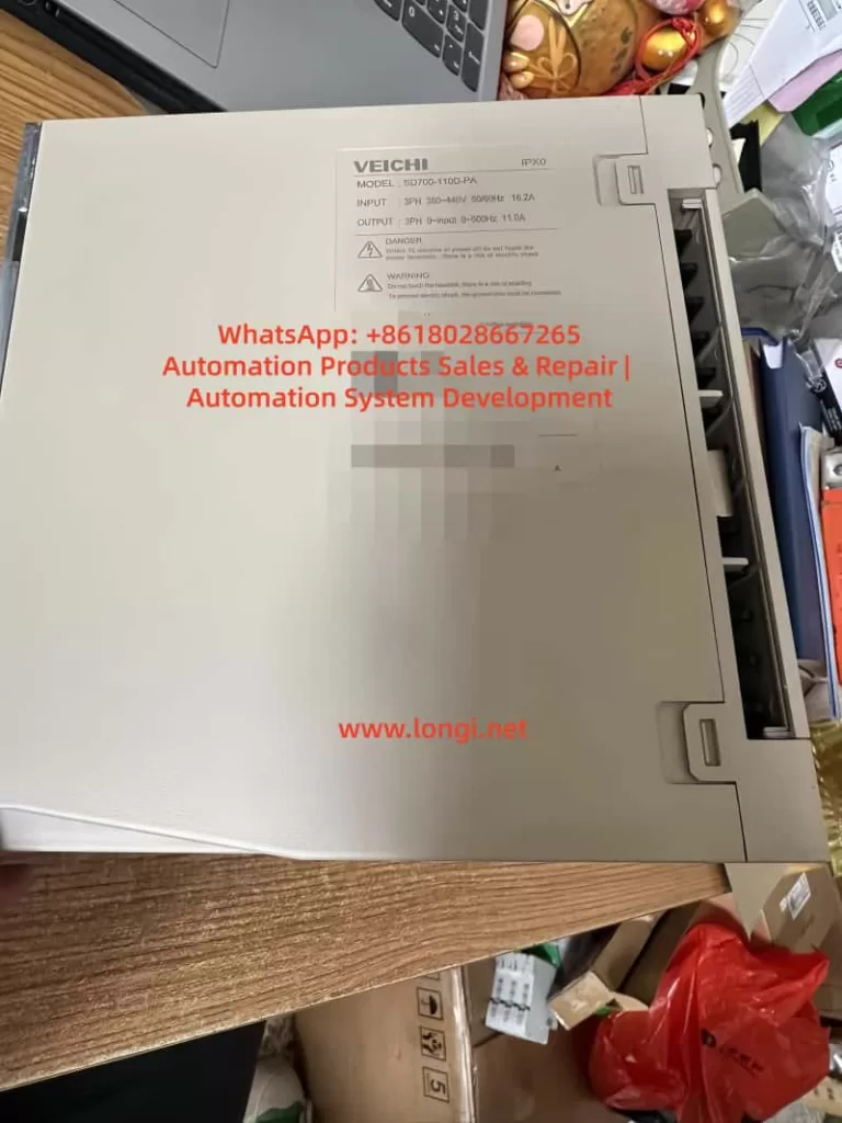
The VEICHI SD700 series servo drive is a high-performance AC servo system suitable for 200V and 400V voltage classes, supporting servo motors with power ranges from 100W to 7.5kW. This system employs advanced vector control technology, combined with high-resolution encoder feedback, to achieve closed-loop control, ensuring high precision and high dynamic response of the system.
Main Component Names and Functions of the System
- Servo Drive Main Body: Includes a display panel, CHARGE indicator light, and CN series interfaces (such as CN1 control terminals, CN2 encoder interface, and CN7 USB communication terminal). The display panel is used to display status codes, fault codes, and parameter settings.
- Servo Motor: Equipped with incremental or absolute encoders, supporting multi-turn absolute position feedback.
- Encoder: The core feedback component, typically with a resolution of 17 or 24 bits, used to provide motor position and speed information.
- System Block Diagram: The main circuit includes power input, regenerative resistor, and motor output; the control circuit involves PLC upper computers, I/O signals, and communication modules. The SD700 supports multiple communication protocols, such as RS485, CANopen, and EtherCAT, facilitating integration into industrial networks. An example of system composition includes an upper computer (such as a PLC), servo drive, motor, and load, forming a closed-loop control link.
Role of the Encoder in the Servo System
The encoder serves as a bridge connecting mechanical and electrical components, converting the physical motion of the motor into digital signals and providing real-time feedback to the drive. The SD700 servo system mainly uses optical incremental or absolute encoders with resolutions as high as 16,777,216 pulses per revolution (24 bits).
Working Principle of the Encoder
The encoder generates A, B, and Z phase signals (for incremental types) or multi-turn absolute position data (for absolute types) through optical or magnetic grating disks. These signals are transmitted to the drive via the CN2 interface, and the drive calculates the motor position, speed, and torque deviations accordingly to achieve PID closed-loop regulation. If communication is interrupted, the drive cannot obtain accurate feedback, leading to system out-of-control and triggering the ER.C90 fault.
Description of the ER.C90 Fault
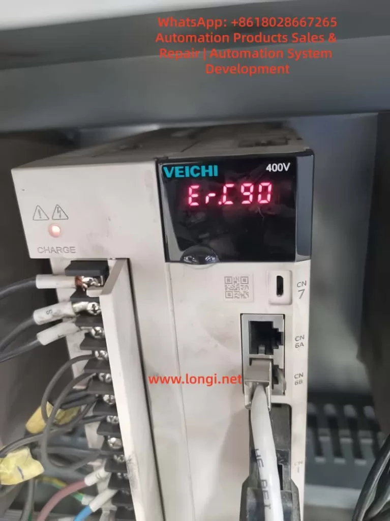
The ER.C90 is a specific fault code for the VEICHI SD700 servo drive, displayed on the panel, such as a red LED showing “ER.C90”. This fault is classified as a “Class 1” alarm, meaning “encoder communication fault: disconnection.”
When the drive detects a loss or abnormality in the encoder signal, it immediately stops the motor output and triggers this alarm. Symptoms include:
- The motor fails to start or stops suddenly.
- The system reports an error and cannot enter the enabled state.
- The upper computer monitoring shows zero or abnormal values for position feedback.
Analysis of Fault Causes
The root cause of the ER.C90 fault lies in the interruption of the communication link between the encoder and the drive. The main reasons include:
- Signal wire disconnection or poor connection: Cable breakage due to bending, pulling, or aging during use. Loose or oxidized CN2 plugs can also cause poor contact.
- Incompatible cable specifications: Using non-original cables or improper shielding layers can lead to signal distortion.
- Excessive cable length: Exceeding the recommended length causes significant signal attenuation.
- External interference: Electromagnetic interference from devices such as frequency converters and welding machines. Improper shielding grounding exacerbates the problem.
- Motor or encoder damage: Failure of the internal photoelectric components of the encoder or wear of the motor bearings leading to unstable signals.
- Incorrect parameter settings: Mismatched motor group parameters or incorrect drive power ratings.
- Drive hardware failure: Damage to the communication module on the main board.
Diagnostic Steps
Diagnosing the ER.C90 fault requires a systematic approach, starting from simple to complex. Ensure that power is disconnected before operation to avoid the risk of electric shock.
- Preliminary Inspection: Observe the panel display to confirm it is an ER.C90 fault. Use the manual FN000 to view the alarm records.
- Cable Integrity Test: Use a multimeter to measure each signal wire of the CN2 interface to check for continuity and short circuits.
- Connection Inspection: Check the CN2 and motor-end plugs for dust, dirt, or oxidation. Re-plug and test.
- Cable Specification Verification: Measure the cable length and confirm that the model matches the requirements in the manual.
- Interference Investigation: Check the shielding layer grounding and keep away from interference sources. Try adding magnetic rings for filtering.
- Parameter Confirmation: Check parameters such as Pn000 (encoder type) and Pn100 (inertia ratio) for correctness.
- Hardware Testing: Replace with spare cables or motors for testing.
- Advanced Diagnosis: Connect the CN7 USB and use upper computer software to monitor Un003 (rotor position).
Solutions
Provide specific solutions for each cause:
- Disconnection/poor connection: Replace the cable or tighten the plugs.
- Incompatible specifications: Select the correct cable model and shorten the length.
- Excessive cable length: Optimize the layout to reduce the length.
- Interference: Improve grounding and add magnetic rings.
- Hardware damage: Replace the encoder or motor.
- Parameter errors: Reset the Pn parameters and restore factory settings before reconfiguration.
- Drive failure: Contact VEICHI after-sales service to replace the unit.
Preventive Measures
Prevention is better than cure. The following strategies can reduce the incidence of the ER.C90 fault:
- Regular maintenance: Check cables and connections every quarter and clean dust.
- Environmental optimization: Install in ventilated cabinets to avoid high temperatures. Use EMI filters.
- Cable management: Use fixed clips to secure cables and prevent pulling.
- Parameter backup: Use the upper computer to export parameters for easy restoration.
- Training: Train operators on correct installation to avoid misoperations.
- Redundancy design: In critical applications, use dual encoders or wireless feedback.
Case Studies
- Case 1: A printing factory using an SD700 servo drive for roller positioning suddenly encountered an ER.C90 fault, and the motor stopped. Diagnosis revealed a broken A-phase wire of the CN2 interface. Replacing the cable and adding a magnetic ring resolved the issue.
- Case 2: A factory had a welding machine nearby with poor grounding, causing interference. Adding shielding resolved the ER.C90 fault.
Advanced Debugging Techniques
For stubborn faults, use the upper debugging tools in Chapter 14 of the manual:
- Upper computer connection: Connect via the CN7 USB, install the driver, and open the software.
- Real-time monitoring: View Un140 bus voltage and Un003 position feedback.
- Digital oscilloscope: Capture the encoder signal waveform and analyze distortion.
- Auxiliary functions: Perform FN105 vibration initialization and use EASYFFT to eliminate mechanical interference.
Conclusion
Although the ER.C90 fault is common, it can be efficiently resolved through systematic diagnosis and guidance from the manual. The VEICHI SD700 servo system is renowned for its high reliability, and correct maintenance can ensure long-term stable operation. This article provides a comprehensive reference, hoping to be of assistance. For more details, refer to the official manual or contact support.