
Introduction
The 455DSP series gaussmeter from Lake Shore Cryotronics is an advanced digital signal processing (DSP)-based magnetic field measurement instrument widely used in scientific research, industrial production, and quality control. Leveraging the Hall effect principle combined with modern DSP technology, it offers high-precision, wide-range magnetic field measurement capabilities. This user guide, based on the official manual (Model 455 Series, Revision 1.5), provides detailed instructions on principles and features, standalone and PC software operation, calibration and maintenance, and troubleshooting. It aims to help users operate the device efficiently and safely. Note: Ensure the model matches the manual during operation.
This guide is structured to first introduce core principles and advantages, then guide operation procedures, followed by maintenance and calibration, and finally analyze fault exclusion.
1. Principles and Features of the Gaussmeter
1.1 Principle Overview
The 455DSP gaussmeter is based on the Hall effect, a phenomenon where a current-carrying conductor in a magnetic field generates a transverse voltage. Specifically, when current flows through a Hall sensor (typically a semiconductor like indium arsenide) placed perpendicular to the current direction in a magnetic field, a Hall voltage proportional to the magnetic field strength is produced. This voltage is amplified and digitized to provide readings of magnetic flux density (B) or magnetic field strength (H).
The instrument employs digital signal processing (DSP) technology to convert analog signals into digital signals for processing, allowing for more precise filtering, compensation, and calculations compared to traditional analog gaussmeters. The system overview is as follows:
- Sampling Data System: While humans perceive the world through continuous analog signals, modern instruments use sampling systems to convert these signals into discrete digital samples. The 455DSP gaussmeter uses an analog-to-digital converter (A/D) to capture Hall voltage at a high sampling rate (e.g., up to 30 readings per second in DC mode), ensuring real-time responsiveness.
- DSP Processing: The DSP chip processes the sampled data, including digital filtering, Fourier transforms (for RMS and peak modes), and compensation algorithms. Limitations include the Nyquist theorem (sampling rate must be at least twice the signal frequency to avoid aliasing) and quantization noise (determined by A/D resolution).
- Measurement Mode Principles:
- DC Mode: Suitable for static or slowly varying magnetic fields. Uses digital filters to smooth noise and provide high-resolution readings. Zero-point calibration eliminates offset using a zero-gauss chamber.
- RMS Mode: Measures the effective value of periodic AC magnetic fields. Uses true RMS calculation to account for waveform distortion. Frequency range up to 1 kHz, supporting broadband or narrowband filtering.
- Peak Mode: Captures peaks (positive/negative) of pulsed or periodic magnetic fields. Sampling rate up to 10 kHz, suitable for transient fields like electromagnetic pulses. Periodic mode continuously updates peaks, while pulse mode captures single events.
- Magnetic Flux Density vs. Magnetic Field Strength: Magnetic flux density (B) is the magnetic flux per unit area, measured in gauss (G) or tesla (T). Magnetic field strength (H) is the intensity generating the magnetic field, measured in amperes per meter (A/m). In vacuum or air, B = μ₀H (μ₀ is the vacuum permeability). The instrument can switch between unit displays.
- Hall Measurement Details: The Hall sensor has an active area (typically 0.5 mm × 0.5 mm), with polarity depending on the magnetic field direction, requiring the sensor to be perpendicular to the field. Probes include transverse and axial types, with a minimum bending radius (2.5 cm) to avoid damage.
1.2 Feature Analysis
The 455DSP gaussmeter integrates multiple innovative features that distinguish it from similar products. Below are detailed descriptions of its measurement, probe, display and interface, and specification features:
- Measurement Features:
- Supports DC, RMS, and peak modes, covering a wide range from microgauss to 350 kG.
- High resolution: 4¾ digits in DC mode, supports frequency measurement (1 Hz to 20 kHz) in RMS mode.
- Auto-ranging (Autorange) and manual range selection for flexibility.
- Max/min hold (Max Hold), relative measurement (Relative), and alarm functions enhance practicality.
- Temperature measurement: Integrated temperature sensor compensates for probe thermal drift, improving accuracy.
- Probe Features:
- Compatible with multiple probes: high-stability (HST), high-sensitivity (HSE), and ultra-high magnetic field (UHS).
- Probe-embedded EEPROM stores serial number, sensitivity, and compensation data for plug-and-play functionality.
- Supports temperature compensation to reduce thermal effect errors (typical <0.02%/°C).
- Extension cables: Up to 100 feet with EEPROM calibration data.
- Bare Hall generators: For custom applications, with specifications including input resistance (typical 600-1200 Ω) and output sensitivity (0.06-0.13 mV/G).
- Display and Interface Features:
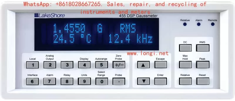
- Dual-line 20-character vacuum fluorescent display (VFD) with adjustable brightness (25%-100%).
- LED indicators: For relative, alarm, and remote modes.
- Keyboard: 22 full-travel keys supporting direct operation, hold, and data input.
- Interfaces: IEEE-488 (GPIB) and RS-232 serial ports for remote control and data acquisition.
- Analog outputs: Three channels (Analog Output 1-3), configurable as ±3V or ±10V, proportional to field value.
- Relays: Two mechanical relays following alarm or manual control.
- Specification Parameters:
- Input type: Single Hall sensor with temperature compensation.
- DC accuracy: ±0.1% of reading ±0.005% full scale.
- RMS accuracy: ±1% (50 Hz-400 Hz).
- Peak accuracy: ±2%.
- Temperature range: 0-50°C, stability ±0.03%/°C.
- Power: 100-240 VAC, 50/60 Hz.
- Dimensions: 216 mm wide × 89 mm high × 318 mm deep, weight 3 kg.
- EMC compatibility: Meets CE Class A standards, suitable for laboratory environments.
- Warranty: 3 years covering material and workmanship defects (excluding improper maintenance).
- Other Advantages:
- Firmware limitations: Ensure accuracy but emphasize result verification.
- Safety symbols: Include warnings, cautions, and grounding identifiers.
- Certification: NIST-traceable calibration, compliant with electromagnetic compatibility directives.
These features make the 455DSP gaussmeter suitable for applications in low-temperature physics, magnetic material testing, and electromagnetic compatibility, providing reliable measurement solutions.

2. How to Use the Gaussmeter Independently and via PC Software?
2.1 Standalone Operation Guide
The 455DSP gaussmeter supports standalone operation without a PC for most measurement tasks. The following steps detail installation, basic operation, and advanced functions.
2.1.1 Installation and Preparation
- Unpacking: Check packaging integrity; accessories include the instrument, power cord, probe (optional), and manual.
- Rear Panel Connections:
- Power input (100-240 V).
- Probe input (15-pin D-type).
- Auxiliary I/O (25-pin D-type, including relays and analog outputs).
- Power Setup:
- Select voltage (100/120/220/240 V).
- Insert fuse (0.5 A slow-blow).
- Connect grounded power cord. Power switch located on the rear panel.
- Probe Connection:
- Insert probe, ensuring EEPROM data is read. Displays “NO PROBE” if no probe is connected.
- Probe Handling:
- Avoid bending probe stem (minimum radius 2.5 cm); do not apply force to the sensor. In DC mode, direction affects polarity.
- Rack Mounting: Optional RM-1/2 kit supports half-rack or full-rack mounting.
2.1.2 Basic Operation
- Power On: Press power switch; display initializes (firmware version). Defaults to DC mode.
- Display Definition:
- Upper line: Field value.
- Lower line: Temperature/frequency.
- Units: G, T, A/m, Oe.
- Brightness adjustment: Hold Display key, select 25%-100%.
- Keyboard Operation:
- Direct keys (e.g., DC/RMS/Peak toggle).
- Hold keys (e.g., zero).
- Selection keys (s/t arrows) and data input.
- Unit Switching: Press Units key, select G/T or A/m/Oe.
- DC Mode:
- Press DC key. Auto/manual range (press Select Range). Resolution and filtering: slow (high precision), medium, fast. Zero-point: insert zero-gauss chamber, press Zero Probe. Max Hold: press Max Hold, captures max/min (algebraic or amplitude). Relative: press Relative, use current field or setpoint. Analog output: proportional to field value.
- RMS Mode:
- Press RMS key. Filter bandwidth: wide (DC-1 kHz) or narrow (15 Hz-10 kHz). Frequency measurement: displays dominant frequency. Reading rate: slow/medium/fast. Max Hold and relative similar to DC mode.
- Peak Mode:
- Press Peak key. Configure periodic/pulse. Displays positive/negative peaks. Frequency measurement supported. Relative and reset available.
- Temperature Measurement: Automatically displays probe temperature (°C or K).
- Alarm:
- Press Alarm, set high/low thresholds, internal/external mode. Buzzer optional.
- Relays:
- Press Relay, configure manual or follow alarm.
- Analog Output 3:
- Press Analog Output, modes: default, user-defined, compensation. Polarity: single/double. Voltage limit: ±10 V.
- Keyboard Lock:
- Press Lock, enter code (123 default).
- Default Parameters:
- Press Escape + Enter to reset EEPROM (does not affect calibration).
2.1.3 Advanced Standalone Operation
- Probe Management:
- Press Probe Mgmt, clear zero-point or temperature compensation.
- User Programming Cable:
- Connect HMCBL cable, press MCBL Program to program sensitivity.
- EMC Considerations:
- Use shielded cables, avoid RF interference. Indoor use, altitude <2000 m.
Standalone operation is suitable for on-site rapid measurements, with a user-friendly interface.
2.2 Using PC Software for Operation
The 455DSP supports IEEE-488 and serial interfaces for remote control and data acquisition, requiring upper computer software like LabVIEW or custom programs.
2.2.1 Interface Setup
- IEEE-488:
- Address 0-30 (default 4), terminator CR LF/LF CR/EOI. Press IEEE to set.
- Serial Port:
- Baud rate (300-9600, default 9600), parity (none/odd/even). Connect DB-9.
- Remote/Local:
- Remote mode LED illuminates; press Local to return to local mode.
2.2.2 Software Operation
- Status System:
- Includes standard event register (ESR) and operation event register (OPST). Use ESE, ESR? to query.
- Command Summary:
- CLS clears, IDN? identifies, *OPC completes. Measurement commands: RDGFIELD? reads field value, RDGMODE sets mode.
- Example Program:
- Use Visual Basic or NI-488.2. Configure GPIB board, send commands like *IDN? to get ID.
- Programming Example:
- Generate SRQ (service request), use *OPC to synchronize operations.
- Serial Port Messages:
- End with , queries end with ?.
- LabVIEW Driver:
- Lake Shore provides; consult availability.
- Troubleshooting:
- Check address/baud rate, ensure terminator. If no response, restart or check cable.
PC operation is suitable for automated testing and data logging, such as analyzing magnetic field distributions with MATLAB.
3. How to Calibrate, Debug, and Maintain the Gaussmeter?
3.1 Calibration and Debugging
Calibration ensures measurement accuracy; recommended annually. Lake Shore provides NIST-traceable services.
3.1.1 Equipment Required
- PC with serial port software.
- Digital multimeter (DMM, e.g., Keithley 2000).
- Precision resistors (22.1 kΩ, 200 kΩ, etc., 0.1% precision).
- Zero-gauss chamber.
3.1.2 Gaussmeter Calibration
- Gain Calibration:
- Use resistors to simulate Hall voltage. Send CALG command to set gain factor (GCF = expected/actual).
- Zero-Point Offset:
- Use CALZ command.
- Temperature Measurement Calibration:
- Excite current (10 μA, 100 μA, 1 mA), measure resistance, calculate GCF.
- Analog Output Calibration:
- Set mode, measure voltage, adjust GCF and OCF.
- Save:
- CALSAVE command stores to EEPROM.
- Debugging:
- Zero-point probe: Insert into zero-cavity, press Zero Probe. Temperature compensation: Press Probe Mgmt to enable. Relative mode debugging: Setpoint verification for deviation. Alarm debugging: Simulate field value to check buzzer/relay. Probe calibration: Calibrate with extension cable. User programming: Input sensitivity (mV/kG).
3.1.3 Maintenance
- Daily Maintenance:
- Keep clean, avoid dust. Storage temperature -20°C to 60°C.
- Probe Maintenance:
- Avoid bending, collision. Regular zero-point checks.
- Power and Fuse:
- Check voltage, replace 0.5 A fuse.
- EMC Maintenance:
- Use shielded cables, short routes, avoid bundling different signals.
- Firmware Updates:
- Consult Lake Shore; no strict deadline.
- Warranty Note:
- Improper maintenance (e.g., modifying firmware) voids warranty.
Maintenance extends lifespan and ensures accuracy.
4. What are the Common Faults of the Gaussmeter and How to Handle Them?
4.1 Common Fault Classification
Faults are categorized into hardware, operational, and interface types. Error messages display on-screen.
4.1.1 Hardware Faults
- No Probe: Probe not connected or damaged. Handle: Check connection, reinsert. If damaged, replace.
- Invalid Calibration: Calibration data corrupted. Handle: Reset EEPROM, press Escape + Enter. Requires recalibration.
- Input Not Responding: Internal communication failure. Handle: Restart; if persistent, return for repair.
- EEPROM Error: Parameters default; recurrence indicates EEPROM defect. Handle: Reset, check calibration.
- Overload: Field exceeds range. Handle: Switch range or remove strong field.
- Temp Overload: Sensor exceeds range. Handle: Cool probe.
4.1.2 Operational Faults
- LOCKED: Keyboard locked. Handle: Input code to unlock.
- Illegal Operation: E.g., Max unavailable in peak mode. Handle: Configure mode.
- Measurement Unstable: Noise or interference. Handle: Enable filtering, shield environment.
4.1.3 Interface Faults
- IEEE-488: No response. Handle: Check address, terminator. Send *CLS to clear.
- Serial Port: Transmission error. Handle: Match baud rate, check parity. Verify TD/RD lines.
- SRQ Failure: Event register issue. Handle: Enable ESE bits, set SRE.
4.1.4 Handling Methods
- General Steps:
- Restart instrument, check cables/power. Refer to error message, press Escape to clear.
- Return to Factory:
- If persistent, provide serial number.
- Prevention:
- Follow safety (e.g., grounding), avoid explosive environments.
- Firmware Issues:
- Verify data if results abnormal; avoid modifying code.
Timely handling ensures reliable operation.
Conclusion
This guide comprehensively covers the use of the 455DSP gaussmeter, helping users progress from basic to advanced operations. For practical application, combine with the manual for experimentation.