
— Practical Insights into D108, AFE2, and A7C1 Alarms
Introduction
The ABB ACS880 drive series, as a new-generation industrial variable frequency drive, is widely applied in cranes, hoists, metallurgy, mining, petrochemical, and other heavy-duty fields. Built on Direct Torque Control (DTC) technology, the ACS880 supports multiple control modes (speed, torque, frequency, process PID) and provides extensive I/O interfaces and fieldbus modules for flexible configuration.
In demanding operating environments, the ACS880 inevitably encounters alarms and faults. Common issues include “End limits I/O error (D108),” “Emergency stop (AFE2),” and “Fieldbus adapter communication warning (A7C1).” This article explores these cases by combining insights from the ACS880 firmware manual and real-world troubleshooting, covering fault mechanisms, root causes, diagnostic procedures, and corrective measures.
I. Overview of ACS880 Control System
1.1 Control Panel and Local/Remote Modes
The ACS880 uses the ACS-AP-x control panel as the human-machine interface. Control can be set to:
- Local control (LOC): Commands originate from the keypad or DriveComposer PC tool.
- Remote control (REM/EXT1/EXT2): Commands are provided via I/O, fieldbus, or external controllers.
1.2 I/O Architecture and Signal Flow
- DI/DO: For limit switches, emergency stops, start/stop logic.
- AI/AO: For speed, current, or process feedback signals.
- RO: Relay outputs for run/fault status.
- Fieldbus interface: Supports PROFIBUS, PROFINET, EtherNet/IP, etc.
1.3 Protection and Fault Logic
The ACS880 provides a wide range of protection functions:
- Motor thermal protection, overcurrent, overvoltage, undervoltage.
- I/O loop monitoring (limit switches/emergency stops).
- Communication timeout protection.
Faults are indicated via Fault codes and warnings via Warning codes.
II. Analysis of Typical Fault Cases
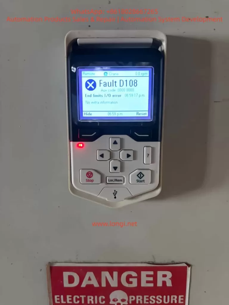
2.1 D108 – End Limits I/O Error
(1) Definition
Indicates an abnormal input from end limit switches, often in crane or hoist applications.
(2) Possible Causes
- Damaged or stuck limit switch.
- Loose or broken DI wiring.
- Incorrect I/O parameter mapping.
- Logic mismatch (NC contact configured as NO).
(3) Diagnostic Steps
- Test switch continuity with a multimeter.
- Inspect wiring and grounding at terminals.
- Verify parameters 10.01–10.10 (DI configuration).
- Check parameter group 04 (Warnings and Faults) for I/O status.
(4) Solutions
- Repair or replace faulty switches.
- Re-tighten wiring connections.
- Correct I/O parameter mapping.
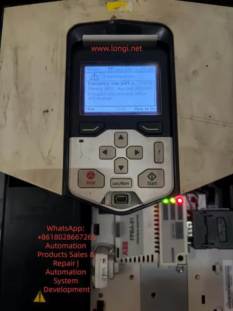
2.2 AFE2 – Emergency Stop (OFF1/OFF3)
(1) Definition
Triggered when the emergency stop circuit is activated, via OFF1/ OFF3 inputs.
(2) Possible Causes
- Emergency stop button pressed.
- Relay or contactor in the safety loop has opened.
- Loose wiring or oxidized contacts.
(3) Diagnostic Steps
- Verify emergency stop button reset status.
- Measure OFF1/ OFF3 input voltage.
- Check parameters 20.01–20.10 (Start/Stop configuration).
(4) Solutions
- Reset E-stop button.
- Replace defective relays or contactors.
- Correct safety loop parameter mapping.
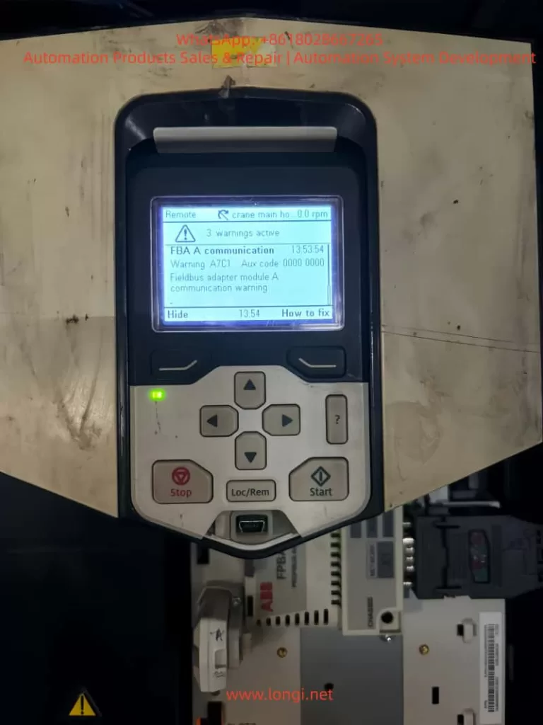
2.3 A7C1 – Fieldbus Adapter Communication Warning
(1) Definition
Indicates communication issues with fieldbus adapter modules such as PROFIBUS/PROFINET FPBA-01.
(2) Possible Causes
- Loose or damaged communication cable.
- Mismatched station number/baud rate between PLC and drive.
- Defective fieldbus module.
(3) Diagnostic Steps
- Check cable connections and shielding.
- Compare station number, baud rate, protocol in PLC and drive.
- Review parameters in group 50/51 (FBA settings).
- Replace FBA module if required.
(4) Solutions
- Reconnect or replace cables.
- Align PLC and drive communication settings.
- Replace or upgrade the module.
III. Systematic Fault Handling in ACS880
3.1 Fault Reset and History Review
- Use the panel “Reset” button or DI input reset.
- Review fault history in group 04 (Warnings/Faults) and group 08 (Fault tracing).
3.2 Signal Monitoring and Diagnostics
- Monitor I/O status in group 05 (Diagnostics).
- Use DriveComposer to trace communication, I/O, and motor signals in real time.
3.3 Maintenance and Prevention
- Regularly inspect limit switches and emergency stop devices.
- Test communication cables periodically.
- Enable automatic fault reset (parameter 31.07) to avoid shutdowns from transient errors.
IV. Application Scenarios and Best Practices
4.1 Crane Systems
- D108 faults often arise from unstable up/down limit switch signals.
- Best practice: dual redundant limit switches plus PLC software limits.
4.2 Metallurgy Hoists
- AFE2 alarms frequently result from worn safety contactors.
- Recommendation: replace relays periodically and enable mechanical brake control (group 44).
4.3 Automated Production Lines
- A7C1 warnings usually caused by configuration mismatches.
- Best practice: export/import FBA configuration files for multiple drives to ensure uniformity.
V. Conclusion
The ABB ACS880 faults D108, AFE2, and A7C1 essentially correspond to I/O errors, emergency stop activation, and communication failures. A structured troubleshooting approach—hardware check → parameter verification → history analysis → module replacement—enables fast problem resolution.
Leveraging the ACS880 firmware manual’s detailed guidance on I/O parameters, fieldbus setup, and fault tracing functions, maintenance teams can not only solve existing issues but also implement preventive measures, reducing downtime and improving system reliability.