Posted on

In-depth Analysis of Siemens SINAMICS S120 F30005 “Power Unit I²t Overload” Fault – Causes and Solutions

1. Introduction

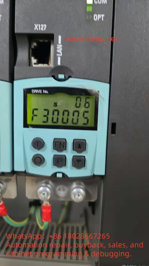
The Siemens SINAMICS S120 series drive system is widely used in multi-axis control, high-dynamic-response, and high-precision industrial applications. However, during operation, users may occasionally encounter the F30005 – Power Unit Overload (I²t Overload) fault.
Once this fault occurs, the drive immediately shuts down the output of the affected power module, causing a production stop. This article combines official manual diagrams, fault descriptions, and real-world cases to provide a systematic analysis of the fault and offer practical solutions.

F30005

2. Definition and Trigger Conditions of F30005

In the SINAMICS S120, thermal protection of the power unit is not only based on temperature sensors but also on an I²t model for thermal load calculation.

  • Principle of the I²t Model
    • I represents current, t represents time.
    • The system calculates the thermal accumulation in the power unit based on current magnitude and duration.
    • When thermal accumulation exceeds the threshold (r0036 = 100%), F30005 is triggered.
  • Trigger Conditions (based on the manual & logic diagram)
    1. Power unit current exceeds rated value for too long.
    2. Insufficient cooling intervals between load cycles.
    3. Load cycle mismatch, resulting in sustained high load.
    4. Power unit or motor is undersized for the actual load.

3. Difference Between F30005 and Other Thermal Faults

According to the manual, the S120’s power unit thermal monitoring generates several alarm/fault codes:

Fault CodeDescriptionDetection Method
F30004Inverter heatsink overtemperatureDirect temperature sensor
F30025/F30026Chip or electronics module overtemperatureChip temperature sensor
F30005Power unit I²t overloadCurrent-time integration model
F30007Rectifier overtemperatureRectifier temperature sensor

Key difference:

  • Overtemperature faults (e.g., F30004) are triggered instantly by high physical temperature readings.
  • F30005 is based on accumulated thermal load — it can occur even if the instantaneous temperature is moderate, as long as the sustained current is too high.

S120

4. Signal Flow and Internal Logic

From the provided manual diagram, the F30005 trigger logic is as follows:

  1. Measure actual absolute current (I_act_abs_value).
  2. Feed the value into the I²t model, along with rated power unit current (r0207).
  3. Calculate power unit load percentage (r0036).
  4. If r0036 ≥ 100%, trigger the “Power Unit Overload” signal.
  5. The control unit issues the F30005 fault and shuts down the module output (Shutdown Type: 2).

5. Common Causes in Practice

  1. Excessive mechanical load
    • Jammed mechanism, high friction, bearing failure, misalignment.
  2. Improper drive settings
    • Acceleration/deceleration times too short, frequent start/stop cycles.
    • Improper torque or speed limit settings.
  3. Undersized drive module
    • Rated current too low for the real load.
  4. Poor cooling or high ambient temperature
    • Inadequate cabinet ventilation, ambient temperature > 40°C.
  5. Load cycle mismatch
    • Frequent high peak loads without adequate cooling periods.

6. Corrective and Preventive Actions

1) Immediate on-site actions

  • Stop and cool: Switch off power, wait for DC LINK capacitors to discharge (>5 minutes), allow the unit to cool.
  • Reset: Clear the fault via the operator panel or control system, and observe if it reoccurs.

2) Medium-term corrective measures

  • Reduce load current
    • Check lubrication, bearing condition, mechanical alignment.
    • Reduce process load or adjust production cycle.
  • Optimize parameters
    • Increase acceleration/deceleration times (p1120/p1121).
    • Lower maximum torque limit (p1520).
  • Improve cooling
    • Increase cabinet airflow.
    • Clean fan filters and check fan operation.

3) Long-term optimization

  • Proper sizing: Replace the Motor Module with a higher current rating if load is consistently near/exceeding nominal current.
  • Load cycle adjustment: Ensure intervals between high-load cycles for cooling.
  • Monitoring and early warning: Use r0036 monitoring — trigger an early warning at 80% load before fault occurs.

6SL3120-2TE13-0AA4

7. Key Parameters and Diagnostic Tools

  • Important monitoring parameters
    • r0036: Power unit I²t load % (0–100%).
    • r0206: Power unit rated power.
    • p0307: Motor rated power.
  • Diagnostic software
    • Use STARTER or TIA Portal to connect to the CU control unit.
    • Check diagnostic buffer for current/load curves before the fault.

8. Conclusion

F30005 “Power Unit I²t Overload” is not just a simple overtemperature issue — it is the result of current and time acting together. It reflects both the mechanical load conditions and the appropriateness of drive sizing and operating strategy.
By understanding the fault mechanism, monitoring key parameters, and applying both immediate and long-term corrective actions, users can significantly reduce the frequency of F30005 faults and ensure stable, efficient operation of the SINAMICS S120 system.


Flowchart – F30005 Fault Trigger Logic & Troubleshooting Steps

             ┌──────────────────────────────────┐
             │   Measure Actual Current (I)      │
             └──────────────────────────────────┘
                           │
                           ▼
             ┌──────────────────────────────────┐
             │ Calculate Thermal Load via I²t    │
             │ Model (r0036 %)                   │
             └──────────────────────────────────┘
                           │
            ┌──────────────┴──────────────┐
            │                             │
     r0036 < 100%                  r0036 ≥ 100%
            │                             │
            ▼                             ▼
 Continue Operation           ┌─────────────────────┐
                              │ Trigger F30005      │
                              │ Shutdown Output     │
                              └─────────────────────┘
                                         │
                                         ▼
                      ┌────────────────────────────────┐
                      │  On-site Actions:               │
                      │  1. Stop & Cool Down             │
                      │  2. Reset Fault                  │
                      └────────────────────────────────┘
                                         │
                                         ▼
                   ┌─────────────────────────────────────┐
                   │ Fault Cleared?                       │
                   └─────────────────────────────────────┘
                          │             │
                        Yes             No
                          │             │
                          ▼             ▼
        ┌─────────────────────────┐   ┌─────────────────────────┐
        │ Monitor r0036 trend &   │   │ Inspect mechanical load, │
        │ optimize parameters     │   │ cooling, and sizing;     │
        └─────────────────────────┘   │ replace module if needed │
                                       └─────────────────────────┘

Posted on

Analysis and Solutions for C-Axis Non-Rotation and Program Errors in Zoller smartCheck 450 Tool Presetter

Problem Description

A Zoller smartCheck 450 fully automatic tool presetter (tool measuring machine) encountered issues where the C-axis failed to rotate and triggered program error alarms during measurement. The user confirmed that no software updates, circuit modifications, or maintenance operations had been performed recently, and the fault persisted after power cycling. Below is a comprehensive analysis of potential causes from aspects such as electrical control failures, encoder/motor issues, software configuration errors, sensor abnormalities, and limit/emergency stop signals, along with corresponding troubleshooting steps and solutions.

Zoller smartCheck 450

1. Electrical Control Cabinet Connection and ZUB Drive Inspection

Possible Causes

  • The C-axis drive signal may not be transmitted properly, often due to loose wiring or power supply failures in the drive. The Zoller smartCheck series typically uses ZUB multi-axis motion control/drive modules to control the X/Z/C axes. Photos of the electrical control cabinet show a drive board labeled “zub” with thick cables MC1, MC2, etc. (presumably motor power and encoder/feedback lines). If these connections are loose, poorly contacted, or broken, the C-axis motor will not receive driving torque or feedback signals, preventing the C-axis from rotating.

Inspection Points

  • Drive Connections: First, power off the machine and open the electrical control cabinet to inspect all connectors related to the C-axis on the ZUB drive. Pay special attention to whether the MC1 and MC2 cable interfaces are firmly plugged in, whether the plug locking mechanisms are in place, and whether there are signs of burn damage, discoloration, or breakage on the plugs and cables. If necessary, disconnect and reconnect them to ensure good contact. Also, check the normal connection of other drive interfaces (such as encoder interface X3, bus interface X8, etc.).
  • Drive Indicators: Check the status indicators or digital displays (if any) on the ZUB drive module. Drives usually have power indicators and fault alarm lights. If there is a fault in the C-axis drive section, a red light may illuminate or an error code may be displayed. Record any abnormal indications for further consultation with the manufacturer’s technical documentation or support engineers.
  • Drive Power Supply: Confirm that the drive power supply is normal. Measure the DC bus voltage or 24V control power supply of the drive (which should be supplied by the switching power supply in the control cabinet). Check whether there are fuses or electronic circuit breaker modules in the control cabinet that control the drive power output. For example, if electronic fuse modules such as Murr are installed in the cabinet, check whether the corresponding channel indicator lights are tripped due to overload (red light constantly on). If tripped, reset or replace the fuses according to the module instructions.
  • Grounding and Shielding: Ensure that the grounding wires of the drive and motor are well connected. Loose grounding or shielding wires can introduce electrical noise and interfere with encoder signals, causing abnormal axis operation.
Zoller smartCheck 450

2. Zoller Control Module (Z1001/Z1004) Status

Possible Causes

  • In addition to the main drive, there are control modules labeled Zoller Z1001 and Zoller Z1004 PZ in the electrical control cabinet. These modules may be responsible for signal distribution, I/O interfaces, or special functions (such as pneumatic control and sensor amplification). If these modules are related to C-axis control, their faults or poor contacts can also cause the C-axis to be uncontrollable.

Inspection Points

  • Module Indicators: Observe the LED indicator states on the Z1001 and Z1004 modules. Normally, these modules should have a constant power indicator (green). In case of a fault, the modules may display a red fault light or flashing codes. Pay special attention to whether there are abnormal indications on modules related to C-axis control (such as Z1004 PZ, which may be related to the rotary axis or pneumatic braking).
  • Wiring Terminals: Gently press the wiring terminals and plugs on each module with your hands to check for looseness. There are multiple rows of wiring on the Z1001/1004 modules. If some signal lines related to C-axis control (such as limit sensors, zero-position sensors, and braking solenoid valves) are loose, the C-axis action will be affected. Retighten all screw terminals and plugs to ensure a reliable connection.
  • Module Functions: Refer to the module manuals for inspection if available. For example, the Z1004 PZ may be a “rotary table control module” (assuming PZ stands for “Prüf-Z Achse” or similar), which may have multiple adjustable potentiometers or fuses. If these fuse elements have tripped, reset or replace them as required. Similarly, the Z1001 may be the main control interface board, and its fault will affect the entire control logic. Check the appearance of these modules for burn damage or component脱落 (detachment). If module damage is suspected, contact Zoller after-sales service for further diagnosis.
Zoller smartCheck 450

3. C-Axis Motor and Encoder Faults

Possible Causes

  • Mechanical or electrical faults may occur in the drive components of the C-axis itself, including motor damage, encoder signal loss, and axis brake not releasing. These will directly cause the axis to be unable to rotate and trigger errors during program execution.

Motor Faults

  • If the C-axis motor has coil burnout, winding short-circuit, or bearing seizure, it will not rotate. In this case, the drive will usually report axis drive faults or short-circuit/overload alarms. Check whether the motor body is overheated, discolored, or has an abnormal odor. Manually rotate the spindle slightly (after ensuring safety and releasing the brake) to feel for excessive resistance or jamming. If the motor is severely damaged, it needs to be repaired or replaced.

Encoder Signal Interruption

  • The C-axis requires an encoder to provide angle feedback. If the encoder is damaged or its signal line is interrupted, the drive will not be able to detect the position and will usually report a large position error or encoder fault alarm, causing the axis to be shut down for protection.
  • Verification Method: Observe whether the C-axis angle reading on the Xpilot software interface changes. Slightly rotate the C-axis after power-off (after ensuring that the brake is released) and then power on to see if the software angle value changes; or manually read the value using the software without triggering the program. If the reading remains constant or changes abnormally, the encoder may have no feedback. In this case, check whether the encoder connection (usually through the MC2 cable) is loose. If necessary, use a multimeter to test the encoder power supply voltage or use an oscilloscope to check the encoder signal quality (this requires the intervention of professionals).

Brake Not Released

  • Many measuring machines have electromagnetic or pneumatic brakes on the C-axis to lock the spindle and prevent rotation (to improve measurement accuracy). During rotation, the controller should unlock the brake. If the brake is stuck or does not receive the unlock command, the motor will be mechanically locked and unable to rotate.
  • Troubleshooting Measures: Listen for the sound of the brake action when the C-axis attempts to rotate (electromagnetic brakes usually make a “click” sound, and pneumatic brakes make an airflow sound). Check whether the solenoid valve or relay that controls the brake works (the corresponding Z1001/1004 module may drive the brake signal). Also, confirm the air pressure: The nameplate of this model indicates that a 6-8 bar air source is required. If the air pressure is insufficient or the air circuit is blocked, the pneumatic brake cannot be released. Check whether the air pressure gauge reading is normal and whether there are air leaks or damages in the relevant air pipes. For electromagnetic brakes, measure whether there is approximately 24V voltage at its power supply terminals when the axis is enabled; if there is no voltage, it means that the control signal is not output, and the control circuit should be checked.

Mechanical Jamming

  • After excluding the above electrical problems, it is not ruled out that the C-axis transmission mechanism is mechanically jammed (such as gear jamming or the clamping mechanism not being fully released). Under the premise of powering off and ensuring safety, manually rotate the C-axis to check its smoothness. If it is obviously unable to rotate and the influence of the brake is excluded, inspect the spindle transmission mechanism for foreign object blockage or damage.
Zoller smartCheck 450

4. Software Configuration and Program Logic Inspection

Possible Causes

  • Software configuration errors or logical conflicts can also cause the C-axis to not rotate and program errors. For example, improper axis parameter configuration in the Xpilot (Pilot 3.0) software or problems in the program flow logic. Although the user stated that no software updates have been performed, the following situations still need to be considered:

Axis Parameter Configuration

  • Enter the machine configuration menu in the Zoller Pilot software and check whether the C-axis is correctly identified and activated. For example, check parameters such as the travel range, zero-point position, and whether CNC control is enabled for the C-axis. Is it possible that the configuration file is damaged or parameters are lost, causing the C-axis to be uncontrolled (for example, abnormal internal controller axis card parameters)? If the configuration is found to be incorrect, restore the correct parameters (refer to the factory backup or contact the manufacturer for information). Pay special attention to the zero-point/reference point setting: Some devices require returning to zero at startup. If the software does not execute the return-to-zero operation and attempts to rotate, an error may be reported. Ensure that the reference points of each axis are initialized according to the correct procedure.

Program Logic Errors

  • Review the measurement program (Sequence) that reported the error. Look for error prompts in the log at the bottom of the Xpilot interface. If the program reports an error at the step where the C-axis motion is called, it may be due to unsatisfied logical conditions. For example, the software may detect that a safety condition is not met (such as the tool not being clamped or exceeding the measurement range) and skip or abort the C-axis rotation. Verify whether the tool is correctly clamped and whether the tool parameters (such as tool length and diameter) in the software are within the allowable range to prevent the program from stopping due to the protection mechanism. You can also try to rotate the C-axis manually: Is there a manual JOG or specific function in the Pilot software to rotate the C-axis? If it cannot be rotated manually, it can basically be determined as a hardware/safety lock problem; if it can be rotated manually but not in the program, there may be a program logic error. In this case, consider re-recording the measurement sequence or checking the C-axis commands in the script.

Software Fault Reset

  • If a software status abnormality is suspected (such as a cache error causing logical confusion), try to reinitialize the software. Close the Xpilot program and turn off the power supply of the industrial control computer. Wait a moment and then restart it to let the control system re-power on and initialize. If the software provides system diagnosis or reset options (such as the Pilot software may have diagnostic tools), run them to detect configuration errors. If necessary, consider backing up the data and then reinstalling or upgrading the software to a stable version to fix potential program bugs.

Internal Controller Parameters

  • The motion control of some Zoller devices may be based on third-party CNC systems (for example, some cases mention that axis board parameter errors in the Syntec CNC system cause IO failures). Although the user has not changed the parameters, it is not ruled out that the controller parameters are disordered due to battery power failure or other reasons. If this situation is suspected, an engineer with permission should enter the controller debugging interface to verify the parameters of each axis, especially the drive configuration and feedback configuration of the C-axis.
Zoller smartCheck 450

5. Sensor Status and Safety Circuit Inspection

Possible Causes

  • Abnormalities in safety protection and position sensors can also cause the C-axis to be locked and unable to rotate, commonly including false alarms from limit switches, unreset emergency stop circuits, and actions of other safety interlocks (such as protective doors and tool clamping sensors).

Limit Switches/Reference Point Sensors

  • Confirm the status of the limit or zero-position sensors of the C-axis. Some tool presetters’ rotary tables may have zero-position sensors or limit switches with limited rotation ranges. If these sensors fail (for example, if the line of a normally closed switch is disconnected, the system will consider it to be in the over-limit position), the control system will prohibit the axis from continuing to move. Check the status of each input signal through the diagnosis interface of the Pilot software: Whether the C-axis limit is triggered (it should be in the normal untriggered state). If necessary, use a multimeter to measure the on-off state of the relevant sensors or lightly拨 (move) the sensor trigger plate to see if the status changes in the software to judge whether the sensor is stuck or the signal line is broken. If a sensor is found to be damaged or misaligned, it needs to be adjusted or replaced and then the alarm should be reset.

Emergency Stop Circuit

  • Confirm that the emergency stop button is fully released and reset and that the safety relay in the emergency stop circuit has been pulled in. Zoller devices usually have a safety circuit to control the drive enable. If the emergency stop circuit is not closed, all axes will be stopped from driving. Check whether the indicator lights of the safety relay (such as Pilz or safety PLC modules) in the control cabinet are normal (usually green indicates closed and red indicates open). If the safety circuit is abnormal, check whether all emergency stop and safety door switches connected in series are closed. In addition, check whether the protective door/cover of the spindle box (if the device has a protective cover) is properly closed and whether the corresponding safety switch is closed.

Tool Clamping Sensor

  • Ensure that the tool clamping status sensor is working properly. During measurement, C-axis rotation usually requires that the tool be properly clamped; otherwise, rotation may be prohibited for safety reasons. If the clamping sensor fails and falsely reports that the tool is not clamped, the software may report an error and abort the C-axis motion. Manually operate the clamping/unclamping and see if the software status indication changes accordingly. If the sensor or its connection is poor, repair it so that the software can detect the tool clamping signal and then reattempt the measurement program.

Other Related Sensors

  • If the device has temperature, air pressure, and other monitoring functions, also confirm that there are no alarms (low air pressure may have been checked in the brake section above). In short, exclude any sensor signals that cause the control system to enter the protection mode.
Zoller smartCheck 450

6. Recommended Troubleshooting Steps and Recovery Measures

For the above possible causes, the following systematic diagnostic steps are recommended to eliminate faults one by one and attempt to restore the C-axis function:

Record Error Information

  • When the fault occurs, record the content of the error dialog box or error code popped up on the Pilot software interface and the fault indications displayed on the drive/module in the control cabinet. This helps with targeted troubleshooting (for example, whether it prompts a drive fault, overtravel, or no reference point).

Preliminary Reset Attempt

  • Press the reset/restore button of the machine (if any) or execute the reset command in the software. Ensure that the emergency stop button is released, and then clear the alarm in the Pilot software. Try to return to zero for each axis (especially the C-axis) and see if it can be completed. If the function is temporarily restored but the fault recurs, continue with the following steps.

Check Safety Status

  • Ensure that all safety conditions are met: the emergency stop is not pressed, the protective door is closed, the air pressure is normal (indicated within the specified range), and the tool is correctly clamped. If any of these conditions are not met, resolve them first (such as releasing the emergency stop and establishing the air source) and then test again.

Power-Off Wiring Inspection

  • Turn off the main power supply of the device and ensure power lockout. Open the electrical control cabinet and focus on checking the wiring and components related to the C-axis:
  • Grip and gently shake the MC1 and MC2 cable connectors on the ZUB drive to confirm that they are not loose. Remove them, check that the pins are not burned or deformed, and then plug them back in firmly.
  • Check whether all plugs and terminals on the Z1001 and Z1004 modules are plugged in tightly, especially the lines marked with the C-axis or spindle braking/sensing. If necessary, re-plug or tighten the screws.
  • Check the power modules, fuses, and relays in the control cabinet: whether the 24V switching power supply output is normal (measure with a multimeter, which should be around 24V); whether the corresponding channel of the electronic fuse module has no red alarm; whether the safety relay indication is normal.
  • Quickly visually inspect all wiring for脱落 (detachment) or broken strands, especially the cables in the drag chain of moving parts (such as the C-axis motor cable) for wear and breakage.

Power Supply and Drive Self-Check

  • Before powering on, manually rotate down the emergency stop/enable switches of devices such as the ZUB drive (if any). After powering on, observe:
  • Whether the power-on indicators on the drive are normally lit and whether a fault is reported immediately (if a red light illuminates immediately, it may indicate a hardware fault).
  • Whether all module indicators are normal (no red lights).
  • Whether no new alarms sound. Then, release the emergency stop/enable of the drive and observe the changes in the drive status lights: if everything is normal, it should enter the standby state.

Test Single-Axis Motion

  • Under the premise of ensuring the safety of the X and Z axes, try to manually operate the C-axis. If the Pilot software provides a JOG or jogging function, give a low-speed rotation command to the C-axis:
  • Normal Motion: If the C-axis can rotate at this time, it indicates that the basic drive hardware is fine, and the problem may lie in the program logic or the previously loose connection has been repaired. You can further test it multiple times to confirm its stability and then run the automatic measurement program.
  • Unable to Move/Report Error: If there is still no response to the manual command and an error is reported, the problem still exists. Check the content of the new error report and focus on whether it prompts a drive fault or a safety interlock. If a drive fault is reported, go to Step 7; if it prompts safety or not ready, go back to Step 3 and check the sections that have not been completely eliminated.

In-Depth Hardware Diagnosis

  • Use tools to further check the motor and encoder:
  • Measure Motor Windings: After power-off, use a multimeter on the ohmmeter range to measure whether the resistances of the three-phase windings of the C-axis motor are balanced and not open-circuit, and whether the insulation to the ground is good. If abnormal (such as open-circuit or short-circuit to the ground), the motor is damaged and needs to be replaced.
  • Check Encoder Feedback: If conditions permit, use an oscilloscope or encoder tester to check the signal quality of the C-axis encoder. If this is not possible, read whether the encoder count changes in the drive diagnosis interface. Any abnormal encoder feedback requires replacing the encoder or repairing the connection fault.
  • Check Brake Control: If it is an electromagnetic brake, measure the voltage at both ends of the brake coil with a multimeter on the DC range when the C-axis is enabled: there should be approximately 24V when released and 0V when powered on but not enabled or when the emergency stop is pressed. If it is always 0V, it means that the control signal is not output (the problem is in the control circuit); if there is 24V but the axis is still locked, it means that the brake is mechanically stuck or not actually released (the problem is in the actuator), and the brake needs to be repaired or replaced. If it is a pneumatic brake, observe the action of the air valve and the change in air pressure before and after enabling the axis: if there is no action, measure the coil of its solenoid valve; if there is action but the pressure is insufficient, check the air circuit.
Posted on

E.ILF Fault Analysis and Solutions for VEKONT C919 Series Variable Frequency Drives

Introduction

Variable Frequency Drives (VFDs), commonly known as frequency converters, are indispensable components in modern industrial automation systems. By adjusting the frequency and voltage of the input power supply, VFDs enable precise control of motor speed and torque, enhancing operational efficiency and significantly reducing energy consumption. The VEKONT C919 series, renowned for its high reliability and advanced features, has gained widespread adoption across various industrial applications. However, as with any complex electronic device, VFDs are susceptible to faults, with the “E.ILF” fault—indicative of an input phase loss—being a critical issue requiring immediate attention. This article delves into the essence of the E.ILF fault, explores its potential causes, and offers detailed solutions to help users restore normal operation, minimize downtime, and ensure optimal performance of the C919 series VFDs.

E.ILF

The Essence of the E.ILF Fault: Understanding Input Phase Loss

The E.ILF fault in the VEKONT C919 series VFD signals an abnormal condition where at least one phase of the three-phase input power supply is missing or not functioning properly. A three-phase power system consists of three alternating current phases, each separated by a 120-degree phase difference, providing a stable and balanced power input to the VFD. The VFD relies on this balanced supply to rectify the AC input into DC power, which is then inverted into variable-frequency AC power to drive the motor.

When one phase is lost—due to either an external power issue or an internal connection fault—the input power becomes unbalanced, potentially leading to the following complications:

  • Voltage Imbalance: The remaining two phases may experience overvoltage or undervoltage, placing additional stress on the VFD’s internal components.
  • Overcurrent Risk: The VFD may attempt to compensate for the missing phase by drawing excessive current through the remaining phases, leading to overheating or component damage.
  • Abnormal Motor Operation: Due to the incomplete power supply, the driven motor may exhibit insufficient torque, increased vibration, or even fail to start.

The E.ILF fault represents a protective mechanism built into the C919 series VFD, designed to detect input phase loss and halt operation to prevent further damage to the equipment or motor. According to the manual on page 12, this fault can stem from various causes, which will be analyzed in detail below.

Possible Causes of the E.ILF Fault

Based on the fault table in the user manual, the E.ILF fault may arise due to the following four potential issues, each pointing to a distinct problem within the system:

1. Abnormal Three-Phase Input Power

This is the most common cause of an input phase loss fault. Abnormalities in the three-phase input power can result from:

  • External Power Issues: Such as a phase outage in the power grid, blown fuses, or tripped circuit breakers.
  • Wiring Problems: Loose, disconnected, or poor-contact connections between the power supply and the VFD.
  • Upstream Equipment Failure: Faults in transformers or generators supplying power, which may result in the loss of one phase.

2. Drive Board Malfunction

The drive board is a critical component that controls the switching of power semiconductor devices (e.g., IGBTs) to facilitate energy conversion. If the drive board fails—due to aging components, overheating, or damage from electrical surges—it may fail to accurately detect or process one of the input phases, triggering the E.ILF fault.

3. Lightning Protection Board Malfunction

The lightning protection board safeguards the VFD against lightning strikes or transient voltage surges. If this board is damaged (e.g., due to a strike or prolonged wear), it may interfere with the normal detection of the input power or even damage the input circuit, leading to a false or actual phase loss fault.

4. Main Control Unit Anomaly

The main control unit serves as the “brain” of the VFD, coordinating overall operation and executing fault detection. If it malfunctions—due to firmware errors, hardware failures, or disrupted internal communication—it may misjudge the input power status, potentially triggering an E.ILF fault even when the three-phase supply is intact.

Steps to Resolve the E.ILF Fault

Addressing the E.ILF fault requires a systematic troubleshooting approach to identify the root cause and implement appropriate measures. Based on the manual’s recommendations to “check and eliminate issues in peripheral circuits” and “seek technical support,” the following detailed steps are proposed:

Step 1: Inspect and Eliminate Peripheral Circuit Issues

Begin by focusing on the external power supply and related circuits to ensure the three-phase input is functioning correctly. Specific actions include:

1. Verify Power Input

  • Use a multimeter to measure the voltage across the VFD’s input terminals (L1, L2, L3), ensuring all three phases are balanced (typically within a 5% deviation) and within the C919 series’ rated range (e.g., 380V ±15%, as specified in the manual).
  • Check the distribution panel for blown fuses or tripped breakers. Replace fuses or reset breakers as needed, and investigate the cause of tripping (e.g., short circuits or overloads).
  • Inspect the wiring from the power source to the VFD for loose connections, breaks, or burn marks, ensuring all connections are secure and intact.

2. Check Upstream Equipment

  • If the power is supplied by a transformer or generator, confirm these devices are operating normally and delivering a stable three-phase output.
  • Use a power quality analyzer (if available) to detect issues like harmonics or voltage sags that might indirectly affect VFD performance.

3. No-Load Testing

  • Disconnect the VFD from the motor load, power on the VFD alone, and observe whether the E.ILF fault persists. If the fault disappears, the issue may lie with the motor or load—e.g., a shorted winding or ground fault—requiring further motor inspection.

Step 2: Internal Troubleshooting and Technical Support

If the peripheral circuits are functioning normally but the fault persists, the issue may lie within the VFD itself. Proceed with caution and seek professional assistance when necessary. Initial troubleshooting steps include:

1. Inspect the Drive Board and Lightning Protection Board

  • Power off the VFD, disconnect it from the power supply, and open the enclosure (ensure capacitors are discharged to avoid electrical shock).
  • Examine the drive board and lightning protection board for visible damage, such as burnt components, swollen capacitors, or cracked solder joints. Replacement may be required if damage is found.
  • Use a multimeter to test the continuity of key components (e.g., diodes and resistors) on the boards to confirm functionality.

2. Inspect the Main Control Unit

  • Reset the VFD to factory settings as per the manual to rule out firmware or configuration errors.
  • If the VFD includes diagnostic software or a display panel, run a self-diagnostic program to check for error codes in the main control unit.
  • Verify that the firmware version is up to date, and contact the manufacturer for updates if needed.

3. Seek Technical Support

  • If the above steps fail to resolve the issue, contact VEKONT technical support or a professional technician, providing a detailed fault description and troubleshooting results to expedite resolution.
  • Depending on the extent of damage, replacement of the drive board, lightning protection board, main control unit, or even the entire VFD may be necessary.
VEKONT C919

Preventive Measures for E.ILF Faults

To reduce the likelihood of E.ILF faults, consider the following preventive measures:

  • Regular Maintenance: Schedule periodic equipment inspections to test power stability, tighten connections, and remove dust or debris (e.g., spider webs visible in the provided photo, which could affect electrical contacts).
  • Install Surge Protection: Add surge protection devices at the power input to ensure the internal lightning protection board functions effectively against lightning strikes or voltage surges.
  • Monitor Power Quality: Use power quality monitoring equipment to promptly identify and address voltage imbalances or harmonic issues.
  • Staff Training: Train maintenance personnel in the operation and troubleshooting of the C919 series VFDs to ensure rapid response to issues.

Conclusion

The E.ILF fault, or input phase loss fault, in the VEKONT C919 series VFD is a critical issue requiring timely intervention. Its essence lies in the imbalance of the three-phase input power supply, which can be caused by external power anomalies, drive board malfunctions, lightning protection board failures, or main control unit errors. By following a structured approach—starting with peripheral circuit checks and escalating to internal troubleshooting with technical support—users can effectively resolve the fault. Additionally, adopting preventive measures such as regular maintenance, surge protection, and power quality monitoring can significantly enhance the VFD’s long-term reliability. This article aims to provide practical guidance for C919 series users, ensuring efficient industrial production and equipment safety.

Posted on

Understanding the Status Icon on ABB ACS880 Drive Panel: Meaning of the Arrow and What Its Disappearance Implies

1. Introduction

In modern industrial automation, the ABB ACS880 series drives are widely used for their robust performance and interactive user interface. Among the display elements on the assistant control panel, the small status icon (typically located at the top-left corner of the screen) plays a vital role. This seemingly minor arrow icon conveys essential information about the drive’s operational state and motor rotation direction. Understanding its function—and especially knowing what it means when the icon disappears—can help engineers diagnose issues quickly and operate the system more effectively. This article explores the icon’s significance and the implications of its absence, along with troubleshooting methods.


Status Icon of acs880 panel

2. What Is the Status Icon and What Does It Indicate?

The status icon is a graphical indicator shown in the Home view of the control panel. It provides a quick visual representation of the motor’s rotation direction and the drive’s operational state.

  • Arrow Direction: When the drive is in local control mode, the arrow points clockwise to indicate forward rotation, and counterclockwise to indicate reverse rotation.
  • Running or Stopped: If the motor is not rotating, the icon may show a numeric value:
    • “1” indicates the drive is in a run state but may not be outputting power.
    • “0” indicates the drive is stopped.

The icon may also display animation or flashing based on the drive status:

Icon StatusMeaning
Static IconDrive is stopped, or start command is inhibited
Flashing IconFault condition, or start command is issued but blocked
Rotating AnimationDrive is running—either with reference = 0 or with load

This compact icon is an intuitive status marker and helps operators understand drive conditions at a glance.


3. What Does It Mean When the Status Icon Disappears?

3.1 Most Common Reason: Remote Control Mode

When the status icon disappears from the upper-left corner of the screen, the most common reason is that the drive has been switched from Local control mode to Remote control mode. In this mode:

  • The drive is controlled via I/O terminals or fieldbus (not the panel).
  • The panel will typically display the word “Remote” instead of the icon.

In other words, the disappearance of the icon is normal behavior when the drive is not under panel control.


3.2 Other Possible Causes

Besides control mode change, here are other less common but relevant causes for the missing status icon:

  1. Communication Failure or Access Restriction
    If the control panel loses communication with the drive or if another device locks control, the panel may not retrieve drive status information.
  2. Modified or Hidden Home View Layout
    The Home view can be customized. If the user or service personnel modified the layout and removed the status section, the icon may no longer appear.
  3. Software Errors or Parameter Misconfiguration
    Though rare, software bugs or misconfigured parameters may cause the icon to not render correctly.

4. Troubleshooting the Missing Status Icon

Here are recommended steps to diagnose and resolve the issue if the status icon is missing:

4.1 Check the Control Mode

  • Look at the top-left of the screen: If “Remote” is shown, the drive is under remote control.
  • Press the Loc/Rem button to switch to Local mode.
  • If the status icon reappears, the issue was due to the control mode setting.

4.2 Verify Panel-to-Drive Communication

  • Check cable connections between panel and drive.
  • If using panel bus with multiple drives, verify the correct drive is selected via Options → Select drive.
  • If communication is unstable, use System info or Diagnostics to confirm panel status.

4.3 Reset the Home View Layout

  • Go to Settings → Reset Home View Layout to restore default display.
  • This ensures the status icon area is re-enabled on the screen.

4.4 Restart the Panel or Drive

  • Power cycle the panel or the entire drive.
  • If the issue persists after restart, consider checking firmware version or configuration settings.
  • Contact ABB service support if necessary.

ACS880-01

5. Conclusion and Recommendations

Though small, the status icon is a powerful visual tool for indicating motor status, rotation direction, and whether the drive is operating. When it disappears, the most likely cause is that the drive is no longer in Local control mode.

Summary of Key Points:

  • Normal Condition: The icon should always be visible in Local mode, indicating status and direction.
  • Icon Disappears: Most likely due to Remote mode.
  • Other Issues: Could include communication errors, customized Home view, or software faults.
  • Recovery Tips:
    • Switch to Local mode using the Loc/Rem button.
    • Restore Home layout if necessary.
    • Verify communication and restart if needed.

Posted on

Understanding and Resolving the E0021 Fault in Hpmont HD20 Series Inverters: A Comprehensive Guide to Control Board EEPROM Read/Write Errors

Introduction

Variable Frequency Drives (VFDs), such as the Hpmont HD20 series, are indispensable in industrial automation, providing precise control over motor speed and torque to enhance efficiency and performance. However, even the most reliable systems can encounter faults that disrupt operations. One such fault, identified by the error code E0021—a “Control Board EEPROM Read/Write Error”—can halt the inverter’s functionality, leading to costly downtime. This article delves into the nature of the E0021 fault, its underlying causes, and offers a detailed, actionable guide to diagnosing and resolving it. Drawing from the HD20 series user manual and fault screenshots, we aim to equip users with the knowledge to restore their inverters efficiently and prevent future occurrences.

E0021

What is the E0021 Fault?

The E0021 fault in the Hpmont HD20 series inverter indicates a Control Board EEPROM Read/Write Error. EEPROM, or Electrically Erasable Programmable Read-Only Memory, is a non-volatile memory type integral to the inverter’s control board. It stores essential data, including:

  • Configuration Parameters: Settings like motor ratings, control modes, and operational limits.
  • User Settings: Custom adjustments made for specific applications.
  • Firmware Data: Variables and instructions critical to the inverter’s software operation.

When the inverter displays the E0021 fault, as shown on the control panel with the illuminated “ALM” (alarm) light and the error code in red, it signifies a failure to read from or write to the EEPROM. This disruption can prevent the inverter from loading its operational parameters, resulting in startup failures, erratic behavior, or complete shutdowns. The user manual and fault description (e.g., “控制板EEPROM读写故障” or “Control Board EEPROM Read/Write Fault”) highlight this as a critical issue requiring immediate attention.

The Nature and Essence of the E0021 Fault

At its core, the E0021 fault reflects a breakdown in the inverter’s ability to manage its stored data. The EEPROM’s role is to ensure that the inverter retains its settings across power cycles, making it a cornerstone of reliable operation. A read/write error could stem from:

  • Data Access Failure: The control board cannot retrieve stored parameters.
  • Data Modification Failure: New settings or updates cannot be saved.
  • Data Integrity Issues: Corrupted data renders the EEPROM unreadable or unusable.

This fault’s essence lies in its potential to compromise the inverter’s functionality entirely. Without access to its configuration, the HD20 series inverter cannot control the connected motor effectively, impacting production lines and industrial processes.

Potential Causes of the E0021 Fault

Understanding the root causes of the E0021 fault is crucial for effective troubleshooting. Based on the fault description and general VFD principles, the following factors may contribute:

  1. Power Supply Instability
    Voltage fluctuations, surges, or sudden power losses can interrupt EEPROM operations. The HD20 series manual (Page 16) specifies a rated voltage (e.g., “额定电压”), and deviations from this range can affect data integrity.
  2. EEPROM Hardware Failure
    The EEPROM chip may degrade over time due to its finite write cycles (typically 100,000–1,000,000) or suffer damage from electrical stress, heat, or manufacturing defects.
  3. Data Corruption
    Electrical noise, improper shutdowns, or electromagnetic interference (EMI) in industrial environments can corrupt the EEPROM’s data, making it inaccessible.
  4. Firmware Issues
    Bugs or corruption in the inverter’s firmware, which manages EEPROM interactions, can lead to read/write errors. An incomplete firmware update could exacerbate this.
  5. Environmental Factors
    The manual (Page 20, “第三条 机械安装”) advises on installation conditions. Excessive heat, humidity, or dust can degrade the EEPROM and control board.
  6. Control Board Malfunction
    Damage to other components, such as solder joints or circuits interfacing with the EEPROM, can disrupt communication.
HD20

Diagnosing the E0021 Fault

Accurate diagnosis is the first step to resolution. Follow these steps to identify the cause:

  1. Observe Symptoms
    • Check the control panel (as per the screenshot) for the E0021 code and “ALM” light.
    • Note if the inverter fails to start, loses settings, or shows additional faults.
  2. Verify Power Supply
    • Measure input voltage with a multimeter to ensure it aligns with the manual’s specifications (e.g., 380V ±15%).
    • Look for fluctuations or noise using an oscilloscope if available.
  3. Inspect the Environment
    • Ensure compliance with installation guidelines (Page 20), checking for proper ventilation, temperature (e.g., 0°C–40°C), and EMI sources.
  4. Power Cycle the Inverter
    • Turn off the inverter, wait 5 minutes, and restart it to rule out temporary glitches.
  5. Check Firmware and Fault Logs
    • Access the fault history via the control panel (“PRG” and “ENT” buttons) to identify patterns.
    • Verify the firmware version against Hpmont’s latest release.
  6. Examine the Control Board
    • Power down safely and inspect for visible damage (e.g., burnt components, loose connections) around the EEPROM chip (often labeled “24Cxx” or “25Cxx”).

Resolving the E0021 Fault

Once diagnosed, apply these solutions tailored to the cause:

  1. Stabilize Power Supply
    • Install a surge protector or UPS to mitigate voltage issues.
    • Ensure proper grounding to reduce EMI.
  2. Reset to Factory Settings
    • Use the control panel to reset parameters (refer to the manual for exact steps, typically via “PRG” and a reset code).
    • Reprogram settings post-reset, using backups if available.
  3. Update Firmware
    • Download the latest firmware from Hpmont’s website and follow update instructions, ensuring an uninterrupted process.
  4. Replace the EEPROM or Control Board
    • If the EEPROM is faulty, a technician can desolder and replace it with an identical chip, reprogramming it with default or backed-up data.
    • For broader control board issues, replace the entire board (e.g., compatible with HD20-4T5PSG), then reset and reconfigure.
  5. Address Environmental Issues
    • Enhance cooling, reduce humidity, or shield the inverter from interference sources.

Preventive Measures

To avoid future E0021 faults:

  • Maintain Power Quality: Use stabilizers and avoid frequent power interruptions.
  • Limit EEPROM Writes: Minimize unnecessary parameter changes.
  • Optimize Environment: Adhere to manual guidelines for temperature and humidity.
  • Regular Maintenance: Inspect and clean the inverter periodically.
  • Backup Parameters: Save settings regularly if the HD20 supports it.

Conclusion

The E0021 fault—Control Board EEPROM Read/Write Error—in the Hpmont HD20 series inverter is a significant challenge that can disrupt industrial operations. By understanding its nature as a data access failure, identifying causes like power instability or hardware issues, and applying systematic diagnosis and resolution steps, users can restore functionality efficiently. Preventive measures further ensure long-term reliability. For persistent issues, Hpmont’s technical support can provide expert assistance, leveraging the manual’s guidance and replacement parts. This comprehensive approach minimizes downtime and sustains the HD20 series’ performance in demanding applications.

Posted on

Understanding and Resolving the Err20 Fault (Module Overcurrent) in Baojie Servo AG Series

Understanding and Resolving the Err20 Fault (Module Overcurrent) in Baojie Servo AG Series

The Baojie Servo AG Series is a widely utilized industrial servo drive system known for its robust performance and advanced control features. However, like any sophisticated machinery, it is susceptible to operational faults, one of which is the “Err20” fault code displayed on the control panel. This error, accompanied by the indication of “module overcurrent,” signals a critical issue that requires immediate attention to prevent damage to the equipment and ensure uninterrupted production. This article delves into the nature of the Err20 fault, its potential causes, diagnostic procedures, and effective resolution strategies, drawing from the technical insights provided in the AG Series user manual.

ERR20

What is the Err20 Fault?

The Err20 fault code on the Baojie Servo AG Series control panel indicates a module overcurrent condition. Overcurrent occurs when the electrical current flowing through the servo drive’s power module exceeds its rated capacity. This can lead to overheating, potential damage to the internal components, or even a complete system shutdown to protect the hardware. The user manual highlights that such faults are part of the system’s safety diagnostics, designed to alert operators to issues that could compromise the drive’s integrity or the machinery it controls.

The display of “Err20” alongside a numerical value (e.g., 20) suggests a specific error category within the fault diagnostic framework outlined in Chapter 8 of the manual, “Fault Diagnosis Explanation.” This chapter emphasizes the importance of understanding alarm codes to identify and rectify underlying issues promptly.

Potential Causes of the Err20 Fault

Several factors can trigger the Err20 fault in the Baojie Servo AG Series. Understanding these causes is the first step toward effective troubleshooting:

  1. Overload Conditions: Excessive mechanical load on the servo motor, beyond its specified capacity, can cause the current to spike, triggering the overcurrent protection. This might occur due to jammed machinery or an improperly calibrated load.
  2. Short Circuits: An unintended electrical connection between the drive’s output terminals (e.g., U, V, W) or within the motor wiring can result in a short circuit, leading to a sudden surge in current.
  3. Faulty Wiring or Connections: Loose, damaged, or incorrectly installed wiring can disrupt normal current flow, potentially causing overcurrent conditions. The manual’s Chapter 3, “Installation and Debugging,” stresses the importance of secure and correct wiring practices.
  4. Component Wear or Failure: Over time, components such as the power module, capacitors, or transistors may degrade, especially if maintenance schedules (detailed in Chapter 9, “Maintenance and Care”) are not followed. A failing component can lead to irregular current draw.
  5. Improper Parameter Settings: Incorrect settings in the drive’s internal parameters, such as those adjustable via the operation panel (Chapter 5, “Parameter Setting Explanation”), can misconfigure the current limits, inadvertently allowing overcurrent situations.
  6. Environmental Factors: Operating the drive in harsh conditions—high temperatures, dust, or humidity—can affect its performance. The manual recommends regular cleaning (e.g., Section 9.4 for 7.5-11kW drive cleaning methods) to mitigate such risks.
PORCHESON AG10

Diagnostic Procedures

To resolve the Err20 fault, a systematic diagnostic approach is essential. The following steps, informed by the manual’s guidelines, should be undertaken:

  1. Initial Safety Check: Ensure the power supply is disconnected, as advised in Section 9.2 for insulation testing, to avoid electrical hazards during inspection.
  2. Visual Inspection: Examine the control panel, wiring, and motor for visible signs of damage, loose connections, or burn marks. Refer to Chapter 3.7 for the control terminal function table to verify wiring integrity.
  3. Review Operating Conditions: Check the mechanical load and operating environment. Compare the current load against the motor’s specifications listed in Chapter 4.7, “Servo Motor Parameter Table.”
  4. Parameter Verification: Access the operation panel (Section 5.1) to review and reset parameters under the “PA” or “PB” menus, ensuring they align with the application’s requirements.
  5. Testing with Diagnostic Tools: Use a multimeter to test for short circuits or abnormal current draw, following the insulation test procedures in Section 9.2. A resistance value of 5 MΩ or higher indicates normal insulation.
  6. Monitor System Logs: If the drive supports logging (as hinted in Chapter 6, “Computer Screen Parameter Monitoring”), review historical data to identify patterns leading to the fault.

Resolution Strategies

Once the cause is identified, the following corrective actions can be implemented:

  • Addressing Overload: Reduce the mechanical load by inspecting and repairing any jams or obstructions. Recalibrate the system to match the load to the motor’s rated capacity, as per the selection guidelines in Chapter 4.9.
  • Fixing Short Circuits: Trace and repair any shorted wires or terminals. Replace damaged cables or connectors, ensuring compliance with the wiring instructions in Chapter 3.11.
  • Repairing Connections: Tighten loose connections and replace any frayed or corroded wires. Refer to the user manual’s wiring diagrams for accuracy.
  • Replacing Faulty Components: If a component failure is suspected, replace it with a compatible part. The manual’s Section 9.3 provides a replacement schedule (e.g., fans every 3 years, capacitors every 5 years), which should guide the decision.
  • Adjusting Parameters: Correct any misconfigured parameters using the panel’s menu system. Ensure changes are made with the power off, as warned in Section 5.5.
  • Environmental Control: Clean the drive using the methods in Section 9.4 (e.g., blowing dust with air) and relocate it if environmental conditions are unfavorable. Install cooling systems if necessary.

Preventive Measures

To prevent recurrence of the Err20 fault, adopt the following practices:

  • Regular Maintenance: Follow the daily checks and periodic maintenance outlined in Chapter 9.1, including insulation tests and component replacements.
  • Training Operators: Ensure personnel are trained in the parameter settings and fault diagnosis procedures detailed in Chapters 5 and 8.
  • Environmental Monitoring: Maintain the operating environment within the recommended temperature and humidity ranges, as noted throughout the manual.
  • Load Management: Regularly assess and adjust the mechanical load to prevent exceeding the drive’s capacity.

Conclusion

The Err20 fault (module overcurrent) in the Baojie Servo AG Series is a critical alert that demands a thorough understanding of its causes and a structured approach to resolution. By leveraging the detailed guidance in the user manual—spanning installation, parameter settings, fault diagnosis, and maintenance—operators can effectively diagnose and rectify this issue. Implementing preventive measures ensures the longevity and reliability of the servo drive system, minimizing downtime and maintaining productivity. For complex cases or persistent faults, consulting the manufacturer’s technical support, as recommended in the manual’s preface, can provide additional expertise. With proactive management, the AG Series can continue to deliver optimal performance in industrial applications.

Posted on

Understanding and Resolving AL.72.8 Fault in Sanyo Denki SanMotion RS2 Series Servo Drivers

Introduction

Sanyo Denki’s SanMotion RS2 series servo drivers are renowned for their precision and reliability in industrial automation applications, such as robotics, CNC machines, and automated manufacturing systems. These drivers are designed to deliver high-performance motion control, but like any sophisticated electronic system, they can encounter faults that disrupt operations. One such fault is the AL.72.8 error code, which, based on available information, likely indicates a ±12V power supply abnormality. This fault can halt critical operations, making it essential for technicians and engineers to understand its causes, troubleshooting steps, and preventive measures. This article provides a comprehensive guide to diagnosing and resolving the AL.72.8 fault, ensuring minimal downtime and sustained system performance.

Understanding the AL.72.8 Fault Code

The AL.72.8 fault code, sometimes displayed as “72H” in hexadecimal format, is believed to indicate an abnormality in the ±12V power supply within the Sanyo Denki SanMotion RS2 series servo driver. The ±12V supply is a critical component that powers various control circuits, including:

  • Encoder Interfaces: For precise motor position feedback.
  • Communication Ports: Such as RS-485 or CANopen, used for interfacing with control systems.
  • Logic Circuits: For processing control signals and ensuring proper operation.

When the ±12V supply deviates from its nominal range (typically ±12V ±10%) or fails entirely, it can lead to erratic behavior, loss of control, or complete system shutdown. The fault is displayed prominently on the driver’s digital panel, as observed in user-provided images, signaling the need for immediate troubleshooting.

Potential Causes of AL.72.8

Several factors can trigger the AL.72.8 fault. Understanding these causes is the first step toward effective resolution:

  1. Internal Power Supply Failure:
    • The servo driver relies on an internal DC-DC converter to generate the ±12V supply from the main AC input (typically 200-240V AC). Failures in this converter, due to component wear, overheating, or manufacturing defects, can result in unstable or absent ±12V output.
    • Symptoms may include intermittent faults, random resets, or loss of communication with the motor or controller.
  2. Short Circuit or Open Circuit:
    • A short circuit in the ±12V line can cause excessive current draw, triggering protective circuits or damaging components.
    • An open circuit, conversely, prevents voltage from reaching critical components, leading to operational failures.
  3. Damaged Components:
    • Components on the control board, such as operational amplifiers, logic ICs, or microcontrollers powered by the ±12V supply, may fail due to overvoltage, overheating, or prolonged use.
    • Visual signs include burnt, discolored, or swollen components, particularly electrolytic capacitors.
  4. Incorrect Wiring:
    • While the ±12V supply is typically internal, external modifications or incorrect wiring during maintenance can introduce faults.
    • Unauthorized changes or loose connections can disrupt the power supply chain.
  5. Main Power Supply Issues:
    • The main AC input voltage must remain within 200-240V AC (±10%) for proper operation. Fluctuations, spikes, or sags can stress the internal DC-DC converter, affecting the ±12V supply.
    • Phase imbalances or power quality issues can exacerbate this problem.
  6. Aging Components:
    • Electrolytic capacitors, commonly used in power supply circuits, degrade over time, losing capacitance or increasing equivalent series resistance (ESR). This can destabilize the ±12V supply, especially under load.
    • Other components, such as voltage regulators, may also deteriorate with prolonged use.

The following table summarizes the potential causes and their impacts:

CausePotential Impact
Internal Power Supply FailureUnstable or missing ±12V supply, system shutdown
Short Circuit/Open CircuitExcessive current or no voltage to circuits
Damaged ComponentsAbnormal voltage behavior, circuit failure
Incorrect WiringDisrupted power supply, erratic operation
Main Power Supply IssuesStress on internal converter, voltage instability
Aging ComponentsReduced performance, intermittent faults

Troubleshooting the AL.72.8 Fault

Resolving the AL.72.8 fault requires a systematic approach to identify and address the root cause. Below are detailed troubleshooting steps:

  1. Verify Main Power Supply:
    • Use a true RMS multimeter to measure the input AC voltage at the driver’s power terminals, ensuring it is within 200-240V AC (±10%).
    • Check for voltage stability using a power quality analyzer if fluctuations are suspected.
    • Ensure the power source is free from phase imbalances or excessive noise.
  2. Inspect Internal and External Wiring:
    • With the power off and proper safety precautions (e.g., wearing ESD-safe gear), open the servo driver.
    • Visually inspect internal wiring for loose connections, burnt wires, or signs of overheating.
    • Check external connections, such as those to the motor or controller, for damage or improper wiring.
  3. Measure ±12V Supply:
    • Locate the ±12V test points on the control board, as specified in the RS2 series service manual.
    • With the driver powered on (in a safe, servo-off state), measure the voltage using a multimeter. The reading should be close to ±12V with minimal ripple (<1% of nominal voltage).
    • If the voltage is out of range, trace the ±12V lines to identify the point of failure.
  4. Check for Short Circuits:
    • Disconnect the driver from power.
    • Use a multimeter in continuity mode to check for shorts between the ±12V lines and ground or other circuits.
    • Measure resistance across the ±12V lines; it should be high (open circuit) unless intentional loads are present.
  5. Inspect Components:
    • Examine the control board for visible damage, such as bulging capacitors, discolored resistors, or burnt ICs.
    • If possible, measure the resistance or capacitance of suspect components and compare with expected values.
  6. Use Diagnostic Tools:
    • Utilize Sanyo Denki’s SANMOTION R Setup Software to access fault logs and additional error codes.
    • Monitor parameters related to power supply status to gain further insight into the fault.
  7. Consult Manufacturer’s Documentation:
    • Refer to the RS2 series manual for specific troubleshooting flowcharts or procedures for AL.72.8.
    • Check for service bulletins or known issues related to this fault code.
  8. Contact Technical Support:
    • If the issue persists, contact Sanyo Denki’s technical support or an authorized service center. Provide the model number, serial number, fault code, and detailed observations from your troubleshooting efforts.
    • Support contact details include:

    The following table outlines the troubleshooting steps and their objectives:

    StepObjective
    Verify Main Power SupplyEnsure input voltage is within specifications
    Inspect WiringIdentify loose or damaged connections
    Measure ±12V SupplyConfirm voltage stability and range
    Check for Short CircuitsDetect electrical faults in ±12V lines
    Inspect ComponentsIdentify damaged or faulty components
    Use Diagnostic ToolsAccess detailed fault logs and parameters
    Consult DocumentationFollow manufacturer’s troubleshooting guide
    Contact Technical SupportObtain expert assistance for unresolved issues

    Preventive Measures

    Preventing the AL.72.8 fault and similar issues requires proactive maintenance and careful system design. Here are key preventive measures:

    1. Regular Maintenance:
      • Schedule inspections every 6-12 months, depending on the operating environment.
      • Clean the driver to remove dust and debris, which can cause overheating or electrical issues.
      • Replace aging components, such as electrolytic capacitors, as per the manufacturer’s maintenance schedule.
    2. Stable Power Supply:
      • Install voltage stabilizers or uninterruptible power supply (UPS) systems to protect against power fluctuations.
      • Ensure the electrical panel includes overcurrent protection and surge suppression devices.
    3. Proper Installation:
      • Mount the servo driver vertically to optimize cooling and ensure adequate airflow.
      • Install in a clean, dry, and well-ventilated environment to prevent overheating and contamination.
    4. Monitor System Performance:
      • Use the driver’s built-in monitoring functions or diagnostic software to log temperatures, voltages, and other parameters.
      • Set up alerts for abnormal conditions, such as voltage deviations or temperature increases.
    5. Training and Documentation:
      • Train maintenance personnel on the specific RS2 series model and its fault codes.
      • Maintain up-to-date documentation, including service manuals and wiring diagrams, for quick reference.

    Conclusion

    The AL.72.8 fault code in Sanyo Denki SanMotion RS2 series servo drivers likely indicates a ±12V power supply abnormality, which can disrupt critical control functions. Potential causes include internal power supply failures, short circuits, damaged components, or main power supply issues. By following a systematic troubleshooting approach—verifying the main power supply, inspecting wiring, measuring voltages, and consulting technical support—technicians can effectively diagnose and resolve the issue. Preventive measures, such as regular maintenance, stable power supply, and proper installation, are essential for minimizing the occurrence of this fault and ensuring the longevity of the servo system. For further assistance, refer to the official Sanyo Denki documentation or contact their technical support team.

    Posted on

    Maintenance Analysis Report on YT‑3300 Smart Positioner Showing “TEST / FULL OUT 7535” Status

    I. Overview and Equipment Background

    This report addresses the status display of the Rotork YTC YT-3300 RDn 5201S smart valve positioner. The front panel shows the following:

    TEST  
    FULL OUT  
    7535
    

    The YT-3300 series smart positioner is produced by YTC (Young Tech Co., Ltd.), often labeled under the Rotork brand. It is designed for precise valve actuator control using a 4–20 mA input signal. The unit supports automatic calibration, self-diagnostics, manual testing, and performance optimization.


    TEST FULL OUT

    II. Interpretation of Display Information

    1. TEST Mode

    The “TEST” message indicates the unit is currently in self-test or calibration mode. This occurs typically during initial power-up, after parameter reset, or when manually triggered.

    2. FULL OUT

    “FULL OUT” means the actuator has moved to the end of its travel range—either fully open or fully closed—depending on the configured logic.

    3. 7535

    The number “7535” is not an error code. It usually represents the raw feedback signal from the internal position sensor, such as a potentiometer or encoder, scaled between 0–9999. This value gives the current travel position.


    III. Possible Root Causes

    The following table summarizes possible causes for this status:

    No.Possible CauseDescription
    1Power-on self-testAfter powering up or parameter loss, the device automatically initiates self-calibration.
    2Manual test triggeredThe test mode may have been manually entered via front-panel buttons.
    3Feedback sensor issueA stuck or damaged position sensor can cause the value (7535) to freeze or become invalid.
    4Air pressure problemInsufficient or unstable air pressure may prevent the actuator from completing movement.
    5Mainboard faultMalfunction of internal controller or microprocessor may lock the unit in test mode.

    YT-3300 RDn 5201S

    IV. Recommended Inspection and Repair Steps

    1. Safety and Initial Checks

    • Disconnect the actuator from live control and ensure safe access.
    • Ensure that air pressure is fully vented to prevent unintended valve motion.
    • Confirm the unit is grounded properly (ground resistance <100 ohms).

    2. Check Air Supply

    • Verify pressure gauges show clean, dry air within 0.14–0.7 MPa (1.4–7 bar).
    • Check for blocked air tubing or clogged filters.

    3. Exit TEST Mode

    • Press the ESC button repeatedly to try returning to the RUN display.
    • If that fails, power cycle the unit and enter Auto Calibration mode via the front panel.

    4. Execute Auto Calibration

    • Set the A/M switch to AUTO.
    • Use the keypad to navigate to “AUTO CAL” or “AUTO2 CAL” and execute.
    • The actuator will automatically stroke to both ends and calibrate zero and full travel points.
    • After successful calibration, the display should return to RUN mode.

    5. Verify Position Feedback

    If the value “7535” remains static or fails to reflect position changes:

    • Open the lower cover and check wiring to the potentiometer (typically yellow, white, blue wires).
    • Measure the feedback voltage (should range from ~0.5 to 4.5V DC).
    • If no variation is detected with actuator movement, the potentiometer or sensor board may need replacement.

    6. Diagnostics and Alarm Monitoring

    • Enter the DIAGNOSTIC menu to check for alarm codes or travel deviation alerts.
    • If high or low limit alarms (e.g., HH ALRM or LL ALRM) are detected, reset as per standard procedures.

    7. Functional Test and Tuning

    • After restoring to RUN mode, input varying mA signals and observe feedback value (PV) changes accordingly.
    • If actuator motion is slow or unstable, adjust Dead-Zone, Gain, or Filter settings to fine-tune performance.
    • Conduct partial stroke tests (PST) if available to verify control reliability.

    TEST FULL OUT

    V. Evaluation and Conclusion

    Depending on the inspection and action taken, the following scenarios are possible:

    • If Auto Calibration completes successfully and feedback changes smoothly: No hardware failure is present. The unit was simply in test mode after reset.
    • If TEST mode persists and feedback value remains frozen: The position feedback sensor or its circuit is likely faulty and needs replacement.
    • If actuator fails to move despite calibration attempts: Check for blocked pneumatic valves, damaged tubing, or insufficient pressure.
    • If diagnostic menu shows active alarms: Follow alarm-specific reset instructions.

    VI. Summary and Recommendations

    1. Preliminary Conclusion: The current “TEST / FULL OUT 7535” status likely indicates a post-reset auto-test, not a malfunction. However, persistent status or failed calibration points to feedback or hardware problems.
    2. Recommended Actions:
      • First attempt to complete auto calibration;
      • Check wiring, feedback sensor, and air supply;
      • Monitor diagnostic menu for error indicators;
      • Replace faulty components if auto-calibration cannot be completed.
    3. Follow-up Advice:
      • Acquire the official user manual for this specific model;
      • Record all air pressures, input/output values, alarms, and parameter settings during troubleshooting for future analysis;
      • If manual steps do not resolve the issue, contact the manufacturer or authorized support for further diagnostics or part replacement.

    Posted on

    Anchuan G9300 Series Frequency Inverter User Manual: Usage Guide

    Abstract

    The Anchuan G9300 series frequency inverter is a high-performance vector inverter widely used in various industrial automation applications. This article will provide a detailed introduction to the operation panel functions, parameter settings, password management, external terminal control, and fault codes and their solutions for the G9300 series frequency inverter, helping users better understand and utilize this equipment.


    G9300

    1. Operation Panel Function Introduction

    The operation panel of the Anchuan G9300 series frequency inverter is designed to be simple and functional, mainly consisting of the following parts:

    • Display Screen: Used to display current operating status, parameter settings, and other information.
    • Function Keys: Include PRG (Programming Key), ENTER (Confirm Key), SHIFT (Shift Key), RUN (Start Key), STOP/RST (Stop/Reset Key), and MF.K (Multi-Function Key).
    • Increment and Decrement Keys: Used to adjust parameter values or browse menus.

    1.1 Restoring Factory Settings

    Before using the G9300 series frequency inverter, it is usually necessary to restore the parameters to factory settings to ensure the device is in a known state. Here are the steps to restore factory settings:

    1. Enter Parameter Setting Mode: Press the PRG key to enter the first-level menu, then press the ENTER key to enter the second-level menu.
    2. Select Parameter Initialization Function: In the second-level menu, find the PP-01 (Parameter Initialization) function code.
    3. Restore Factory Parameters: Set PP-01 to 1, then press the ENTER key to confirm. At this point, all parameters of the frequency inverter will be restored to factory settings.

    1.2 Setting and Removing Passwords

    To protect parameter settings from being arbitrarily changed, the G9300 series frequency inverter provides a password protection function. Here are the steps to set and remove passwords:

    1. Setting a Password:
      • Enter the parameter setting mode and find the P7-11 (User Password) function code.
      • Set P7-11 to the desired password value (range 0~32766), then press the ENTER key to confirm.
    2. Removing a Password:
      • Enter the parameter setting mode and find the P7-11 function code.
      • Set P7-11 to 0, then press the ENTER key to confirm, and the password will be removed.

    1.3 Parameter Access Restrictions

    To further protect parameter settings, the G9300 series frequency inverter also provides a parameter locking function. Here are the steps to set parameter access restrictions:

    1. Locking Parameters:
      • Enter the parameter setting mode and find the PP-04 (Parameter Lock) function code.
      • Set PP-04 to 1, then press the ENTER key to confirm. At this point, all parameters will be locked and cannot be changed.
    2. Unlocking Parameters:
      • Enter the parameter setting mode and find the PP-04 function code.
      • Set PP-04 to 0, then press the ENTER key to confirm, and the parameter lock will be removed.

    2. External Terminal Forward/Reverse Control and External Potentiometer Speed Regulation

    The G9300 series frequency inverter supports forward/reverse control and potentiometer speed regulation through external terminals, making it very flexible and convenient in industrial automation control.

    2.1 External Terminal Forward/Reverse Control

    To achieve external terminal forward/reverse control, the following wiring and parameter settings are required:

    1. Wiring:
      • Connect the forward control signal to the DI1 terminal.
      • Connect the reverse control signal to the DI2 terminal.
      • Ensure the ground terminal (GND) is correctly connected.
    2. Parameter Settings:
      • Enter the parameter setting mode and find the P4-00 (DI1 Terminal Function Selection) and P4-01 (DI2 Terminal Function Selection) function codes.
      • Set P4-00 to 1 (Forward Operation), and P4-01 to 2 (Reverse Operation), then press the ENTER key to confirm.

    2.2 External Potentiometer Speed Regulation

    To achieve external potentiometer speed regulation, the following wiring and parameter settings are required:

    1. Wiring:
      • Connect the output of the potentiometer to the AI1 terminal.
      • Ensure the ground terminal (GND) is correctly connected.
    2. Parameter Settings:
      • Enter the parameter setting mode and find the P0-03 (Main Frequency Source A Selection) function code.
      • Set P0-03 to 4 (Keypad Potentiometer), then press the ENTER key to confirm.

    3. Fault Codes and Their Solutions

    During the use of the G9300 series frequency inverter, various faults may be encountered. Here are some common fault codes and their solutions:

    Fault CodeFault DescriptionSolution
    E001IGBT Short Circuit FaultCheck the IGBT module and its drive circuit, replace the IGBT module if necessary.
    E002Acceleration OvercurrentCheck if the acceleration time setting is too short or if the load is too large, adjust the acceleration time or reduce the load.
    E003Deceleration OvercurrentCheck if the deceleration time setting is too short or if the load is too large, adjust the deceleration time or reduce the load.
    E004Constant Speed OvercurrentCheck if the load is too large or if the motor parameters are set correctly, reduce the load or reset the motor parameters.
    E005Acceleration OvervoltageCheck if the acceleration time setting is too short or if the bus voltage is too high, adjust the acceleration time or check the bus voltage.
    E006Deceleration OvervoltageCheck if the deceleration time setting is too short or if the bus voltage is too high, adjust the deceleration time or check the bus voltage.
    E007Constant Speed OvervoltageCheck if the bus voltage is too high or if the load is too small, adjust the bus voltage or increase the load.
    E008Stop OvervoltageCheck if the stop mode setting is correct or if the bus voltage is too high, adjust the stop mode or check the bus voltage.
    E009UndervoltageCheck if the input voltage is normal or if the power line is in good contact, ensure the input voltage is stable.
    E010Inverter OverloadCheck if the load is too large or if the heat dissipation is good, reduce the load or improve the heat dissipation conditions.
    E011Motor OverloadCheck if the motor load is too large or if the heat dissipation is good, reduce the load or improve the heat dissipation conditions.
    E012Input Phase LossCheck if the input power supply is missing a phase, ensure all three phases are normally powered.
    E013Output Phase Loss or Three-Phase Output ImbalanceCheck if the output line is normal, ensure the three-phase output is balanced.
    E014Module OverheatCheck if the heat sink is blocked or if the ambient temperature is too high, ensure good heat dissipation.
    E015External FaultCheck if the external control line is normal, ensure the external control signal is correct.
    E016Communication AbnormalityCheck if the communication line is normal or if the communication parameters are set correctly, ensure stable communication.
    E017Motor Tuning AbnormalityCheck if the motor parameters are set correctly, re-perform motor tuning.
    E018Parameter Read/Write AbnormalityCheck if the parameter settings are correct, reset the parameters.
    E019Inverter Hardware AbnormalityCheck if the inverter hardware is normal, contact after-sales service if necessary.
    E020Motor Ground Short CircuitCheck if the motor line is short-circuited, ensure the motor insulation is good.
    E021AD Zero Drift Too LargeCheck if the analog input circuit is normal, contact after-sales service if necessary.
    E022Inverter Hardware Abnormality (Clear Latch Timeout)Check if the inverter hardware is normal, contact after-sales service if necessary.
    E023Motor Ground Short CircuitCheck if the motor line is short-circuited, ensure the motor insulation is good.
    E024AD Zero Drift Too LargeCheck if the analog input circuit is normal, contact after-sales service if necessary.
    E025User-Defined Fault 1Check if the setting of user-defined fault 1 is correct, ensure the logic is correct.
    E026User-Defined Fault 2Check if the setting of user-defined fault 2 is correct, ensure the logic is correct.
    E027Power-On Time ReachedCheck if the power-on time setting is correct, adjust the power-on time appropriately.
    E028PID Feedback Disconnection FaultCheck if the PID feedback line is normal, ensure the feedback signal is stable.
    E029PID Feedback Overlimit (Overvoltage) FaultCheck if the PID feedback signal is too large, adjust the PID parameters appropriately.
    E030Keypad STOP Key Stop FaultCheck if the STOP key is normal, ensure the control logic is correct.
    E031Hardware Current Limit TimeoutCheck if the current limit setting is correct or if the load is too large, adjust the current limit parameters or reduce the load.
    E032Auto-Reset Count ExceededCheck if the auto-reset count setting is correct, adjust the reset count appropriately.

    Standard Wiring Diagram for G9300

    4. Conclusion

    The Anchuan G9300 series frequency inverter is a powerful and high-performance industrial automation device. Through this article, users can better understand and use this equipment, including operation panel functions, parameter settings, password management, external terminal control, and fault codes and their solutions. In practical applications, users should perform parameter settings and fault troubleshooting according to specific needs to ensure the stable operation and high efficiency of the equipment.

    It is hoped that this article can help users better master the usage methods of the Anchuan G9300 series frequency inverter and improve the efficiency and quality of industrial automation control.

    Posted on

    K-DRIVE KD600M Series Variable Frequency Drive User Manual Guide

    Introduction

    The K-DRIVE KD600M series variable frequency drive (VFD) is a powerful and versatile device designed for motor speed and torque control in various industrial applications. This guide, based on the K-DRIVE KD600M series user manual, provides a detailed overview of the operation panel functions, parameter initialization, password and parameter access restrictions, external terminal forward/reverse control and potentiometer speed adjustment, as well as common fault codes and their resolutions. By mastering these features, users can operate and maintain the VFD efficiently and safely, ensuring optimal performance across different scenarios.

    KD600M-4T-2.2G

    Operation Panel Functions

    The KD600M series VFD’s operation panel is the central interface for user interaction, integrating intuitive buttons, LED indicators, and a 5-digit display for parameter settings, status monitoring, and motor control. Below are the key functionalities:

    Buttons and Controls

    The panel includes the following buttons:

    • PRG: Enters programming mode to access parameter menus.
    • ESC: Exits the current menu or cancels an operation.
    • OK: Confirms parameter settings or selections.
    • RUN: Starts motor operation.
    • STOP: Stops motor operation or resets faults.
    • QUICK: Quickly sets commonly used parameters.
    • JOG: Enters jog mode for testing or fine-tuning.
    • UP/DOWN: Adjusts parameter values or navigates menus.

    For example, to adjust the frequency from 0.00Hz to 5.00Hz, users can press PRG to enter the parameter menu, use the UP/DOWN keys to select the target parameter (e.g., P1-04), input the new value, and press OK to confirm.

    LED Indicators

    The panel’s LED indicators provide real-time status feedback:

    • RUN: Green, on indicates running, off indicates stopped, flashing indicates sleep mode.
    • L/D/C: Red, off indicates panel control, on indicates terminal control, flashing indicates communication control.
    • FWD/REV: Red, off indicates forward, on indicates reverse, flashing indicates direction mismatch.
    • TUNE/TC: Red, on indicates torque control, flashing indicates tuning or a fault.

    Display Screen

    The 5-digit LED display shows frequency, current, voltage, fault codes, and other information. Hexadecimal values are prefixed with “H.” (e.g., P7-29 displays as “H.3f”). The display supports multi-level menu navigation (group → code → value), enabling quick access and modification of parameters.

    Related Parameters

    Key parameters related to operation panel functions include:

    • P7-00 (Jog Run Frequency): Range: 0.00Hz to maximum frequency; Factory default: 6.00Hz.
    • P7-01 (Jog Acceleration Time): Range: 0.0s to 3000.0s; Factory default: 10.0s.
    • P7-02 (Jog Deceleration Time): Range: 0.0s to 3000.0s; Factory default: 10.0s.
    • P7-28 (QUICK/JOG Key Function Selection): Options: 0 (forward jog), 1 (forward/reverse switch), 2 (reverse jog), 3 (panel/remote switch), 4 (panel frequency source switch); Factory default: 0.
    • P7-16 (Keyboard Knob Precision): Options: 0 (0.01Hz) to 10 (10Hz); Factory default: 2.

    These features make the operation panel a powerful and flexible tool for various control needs.

    Parameter Initialization

    Parameter initialization is a critical step for restoring default settings or backing up user configurations. The KD600M series offers the following function codes:

    P0-28 (Parameter Initialization)

    • Options:
      • 0: No operation
      • 1: Restore factory settings (excludes motor parameters, records, and P0-20)
      • 2: Clear records
      • 3: Back up user parameters
      • 4: Restore backed-up parameters
    • Factory Default: 0
    • Modifiable State: Running state (★)

    To perform initialization, users should enter P0-28 while the device is stopped, set it to 1, and confirm. The VFD will revert to factory settings, preserving motor parameters and run records.

    P0-29 (Parameter Upload/Download)

    • Options:
      • 0: No function
      • 1: Upload parameters
      • 2: Download parameters (excludes P4 and A1)
      • 3: Download parameters (includes P4 and A1)
      • 4: Download all parameters
      • 5-7: Download modified parameters
    • Factory Default: 0
    • Modifiable State: Stopped or running state (☆)

    This function allows users to back up custom parameters or restore from a backup, suitable for multi-device configurations or fault recovery.

    Password and Parameter Access Restrictions

    To prevent unauthorized modifications, the KD600M series provides password protection and parameter access restrictions:

    Password Protection

    • P7-49 (User Password):
      • Range: 0 to 65535
      • Factory Default: 0
    • PF.00 (Factory Password):
      • Range: 0 to 65535
      • Factory Default: ***** (hidden for security)

    Users can enable password protection by setting P7-49. Fault codes like Err25 (EEPROM read/write failure) or Err1A (password entry limit exceeded) may indicate password-related issues, requiring EEPROM chip inspection or technical support.

    Parameter Access Restrictions

    • B0-00 (Function Code Read-Only Selection):
      • 0: Invalid (no restriction)
      • 1: Read-only (parameters cannot be modified)
      • Factory Default: 0
    • Parameter Status:
      • : Not modifiable during operation (e.g., P0-03: motor control).
      • : Manufacturer-only modification.
      • : Read-only (e.g., PF group parameters).

    These restrictions ensure the security of critical parameters, preventing accidental changes or unauthorized access.

    External Terminal Forward/Reverse Control and Potentiometer Speed Adjustment

    The KD600M series supports external terminal control for forward/reverse operation and potentiometer speed adjustment, ideal for automated systems.

    Forward/Reverse Control

    • Digital Input Terminals (DI1-DI10):
      • DI1: Default forward (function code 1).
      • DI2: Default reverse (function code 2).
      • Supports PNP/NPN modes, switchable via DIP switches.
      • Up to 10 digital inputs with optional IO1/IO2 expansion cards.
    • P5-11 (Terminal Command Mode):
      • 0: Two-wire mode 1
      • 1: Two-wire mode 2
      • 2: Three-wire mode 1
      • 3: Three-wire mode 2
      • Factory Default: 0

    Wiring Method:

    • Connect DI1 and DI2 to a PLC or switch, with the COM terminal as the common return.
    • Ensure secure connections to avoid short circuits or poor contact.

    Potentiometer Speed Adjustment

    • Analog Input Terminals (AI1, AI2):
      • Supports 0-10V or 4-20mA input.
      • P5-15 (AI1 Minimum Input): Range: 0.00V to 10.00V; Corresponding setting: -100.0% to 100.0%.
      • P5-16 (AI1 Maximum Input): Range: 0.00V to 10.00V; Corresponding setting: -100.0% to 100.0%.
    • Wiring Method:
      • Use a 1-5kΩ potentiometer, connecting to AI1 and +10V-GND terminals (+10V provides up to 10mA power).
      • Recommended wiring length is less than 20 meters to minimize signal interference.

    Setup Steps:

    1. Set P5-11 to 0 (two-wire mode 1) to enable terminal control.
    2. Configure P5-15 and P5-16 to define the potentiometer input range.
    3. Rotate the potentiometer and observe frequency changes on the display to ensure proper speed adjustment.

    Common Fault Codes and Resolutions

    The KD600M series manual lists various fault codes with corresponding resolution methods. Below are common faults and their troubleshooting steps:

    Fault CodeFault NameResolution Method
    Err01Inverter Module ProtectionCheck U, V, W terminals for shorts or grounding, inspect overheating, wiring, fans, and vents; contact support if unresolved.
    Err04Acceleration OvercurrentCheck output circuit, motor parameters, acceleration time (P9-22), V/F gain, voltage, load, and VFD capacity; adjust parameters.
    Err05Deceleration OvercurrentCheck output circuit, motor parameters, deceleration time (P9-23), voltage, load, brake unit/resistor, and flux gain; adjust parameters.
    Err06Constant Speed OvercurrentCheck output circuit, motor parameters, voltage, load, and VFD capacity; adjust parameters.
    Err08Acceleration OvervoltageCheck voltage, external force, acceleration time, brake unit/resistor, and motor parameters; adjust settings.
    Err09Deceleration OvervoltageCheck voltage, external force, deceleration time, and brake unit/resistor; adjust settings.
    Err10Constant Speed OvervoltageCheck voltage, external force, and resistor installation; adjust parameters.
    Err12Undervoltage FaultCheck power stability, voltage range, bus voltage, rectifier, and drive/control board; reset or contact support.
    Err13Drive OverloadReduce load, check motor condition, consider upgrading VFD.
    Err14Motor OverloadAdjust P9-01 settings, check load and motor condition, upgrade VFD if needed.
    Err15Drive OverheatingLower ambient temperature, clean vents, check fans and thermistor, replace module if necessary.
    Err17Current Detection FaultCheck wiring, current devices, and main/control board; contact support.
    Err20Ground Short CircuitCheck motor and cables for shorts, replace if needed; contact support.
    Err23Input Phase LossCheck power supply, drive/lightning/main board; contact support.
    Err24Output Phase LossCheck motor wires, output balance, drive/module; resolve fault or contact support.
    Err25EEPROM Operation FailureCheck EEPROM chip, replace main board if necessary; contact support.
    Err27Communication FaultCheck host, communication settings, and P8 group parameters; adjust wiring/parameters.
    Err28External FaultCheck DI terminal input, reset fault.
    Err29Speed Deviation ExcessiveExtend acceleration/deceleration time, reset P9-31/P9-32.
    Err30/31User-Defined Fault 1/2Check DI terminal input, reset fault.
    Err32PID Feedback LossCheck feedback signal, reset PA-13.
    Err33Quick Current LimitReduce load, extend acceleration time, or upgrade VFD.
    Err34Load Drop FaultReset or adjust P9-28 to P9-30 conditions.
    Err35Input Power FaultAdjust voltage, extend power cycle.
    Err37Parameter Storage AnomalyCheck DSP-EEPROM communication, replace main board if needed.
    Err39Run Time ReachedCheck run time, reset if necessary.
    Err40Cumulative Run Time ReachedCheck cumulative run time, reset.
    Err42Motor Switching During RunEnsure correct motor switching procedure.
    Err46Master-Slave Communication InterruptCheck master-slave communication connections.

    General Fault Handling Steps

    1. Power Off Check: Disconnect the VFD power before addressing any fault to ensure safety.
    2. Refer to Manual: Consult the manual’s troubleshooting section for specific steps based on the fault code.
    3. Parameter Adjustment: Adjust relevant parameters (e.g., acceleration time P9-22, deceleration time P9-23) according to the fault cause.
    4. Reset: Use the STOP key or set P9-11 (auto-reset attempts, 0-20, default 0) and P9-13 (reset interval, 0.1s-100.0s, default 1.0s) to reset faults.
    5. Technical Support: Contact K-DRIVE technical support if the fault persists.
    K-DRIVE KD600M

    Conclusion

    The K-DRIVE KD600M series VFD offers robust control capabilities through its intuitive operation panel, flexible parameter settings, and powerful external control features. By mastering the operation panel functions, parameter initialization, password protection, external terminal control, and fault resolution methods, users can ensure stable operation across various industrial scenarios. It is recommended to always refer to the user manual for detailed guidance and safety precautions to maximize the device’s performance and longevity.