Posted on

Yaskawa V1000 Series “CALL” Fault Analysis and Resolution Methods

Introduction

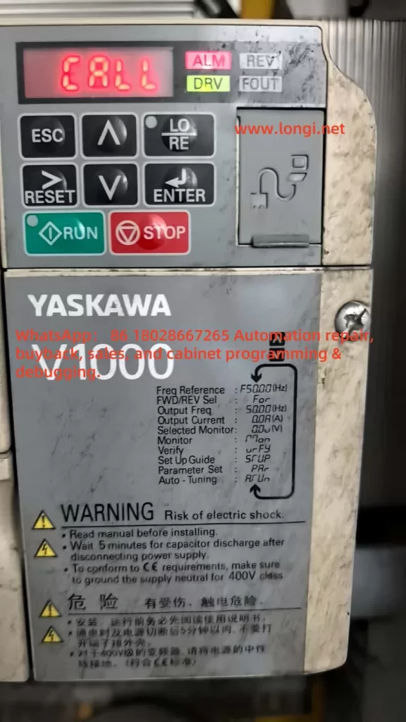
The Yaskawa V1000 series inverter is renowned for its efficient vector control performance and wide range of applications, making it a vital component in industrial automation, including systems like fans, pumps, and conveyor belts. However, during operation, the inverter may encounter various faults, with the “CALL” fault being a common communication-related issue. When the inverter’s display shows “CALL” accompanied by the ALM (alarm) light turning on, it typically indicates a communication link abnormality, which may result in system shutdown. This article provides an in-depth analysis of the nature of the “CALL” fault, its causes, and resolution methods, along with preventive measures to help users quickly restore equipment operation and enhance system reliability.

V1000 call

Nature of the “CALL” Fault

In the Yaskawa V1000 series inverter, “CALL” generally signifies a communication-related issue, potentially indicating that the inverter is awaiting a signal from a master device (e.g., PLC) or has detected an error in the communication link. In some instances, “CALL” may serve as a general prompt, urging users to investigate specific fault codes (e.g., “CE” for MEMOBUS/Modbus communication errors) further. The illumination of the ALM light suggests the inverter has detected an abnormal state, typically interrupting output and allowing the motor to enter a free-stop mode.

Based on relevant documentation, while “CALL” is not explicitly listed in the V1000 series fault code table, it is closely related to communication problems, possibly linked to codes like “CE” (MEMOBUS/Modbus communication error) or “bUS” (option card communication error). In certain communication protocols (e.g., Modbus), “CALL” might indicate a more severe communication issue, potentially necessitating inverter replacement.

Causes of the “CALL” Fault

The occurrence of a “CALL” fault may be attributed to the following causes:

  1. Communication Cable Wiring Issues:
    • Loose, broken, or short-circuited communication cables can lead to data transmission failure.
    • Incorrect wiring (e.g., improper terminal connections) may prevent communication between the inverter and the master device.
  2. Communication Parameter Configuration Errors:
    • Mismatched communication parameters (e.g., HS-01 slave address, HS-02 communication speed, HS-03 parity) with the master device.
    • For example, if the inverter’s baud rate is set to 9600 bps while the PLC is set to 19200 bps, communication will not establish.
  3. Hardware Problems:
    • Failure or improper installation of communication option cards (e.g., Modbus, CC-Link, or PROFIBUS-DP cards).
    • Damaged or poorly contacted communication terminals.
  4. Electromagnetic Interference (EMI):
    • Common electromagnetic noise in industrial environments (e.g., from motors or transformers) may disrupt communication signals, causing data transmission errors.
  5. Master Station Program Errors:
    • Incorrect configuration in the master device (e.g., PLC) may prevent proper command transmission or response reception.
    • For instance, the PLC may not have the correct slave address or communication protocol set.
  6. Communication Timeout:
    • If the inverter does not receive a response from the master within a specified time (e.g., as set by parameter HS-09), it may trigger a “CALL” fault.

Steps to Resolve the “CALL” Fault

To effectively address a “CALL” fault, follow these troubleshooting and resolution steps:

CIMR-VB4A0018FBA

Step 1: Inspect Physical Connections and Wiring

  • Check Cables: Inspect communication cables for damage, breaks, or short circuits. Ensure the correct cable type (e.g., RS-485 or RS-422) is used.
  • Verify Connections: Confirm all terminals are securely connected with no looseness or poor contact.
  • Refer to Manual: Ensure terminal connections (e.g., R+, R-, S+, S-) are correct as per the Yaskawa V1000 technical manual.

Step 2: Verify Communication Parameters

  • Use the inverter’s digital operator panel or programming software (e.g., DriveWorksEZ) to check the following parameters:
    • HS-01 (Slave Address): Set to a unique address between 1-247, matching the master device.
    • HS-02 (Communication Speed): Confirm baud rate (e.g., 9600, 19200 bps) matches the master.
    • HS-03 (Parity): Select the appropriate parity setting (none, odd, even).
    • HS-04 (Fault Action Selection): Define the action upon communication failure (e.g., decelerate to stop or free stop).
    • HS-09 (Timeout Time): Adjust timeout to suit system needs.
  • Save changes and retest communication.

Step 3: Perform Self-Diagnostic Test

  • Per the technical manual, set parameter H1-06 to 67 to enter communication test mode.
  • Power off, connect test terminals, power on again, and check if the display shows “PASS” (normal) or “CE” (fault).
  • This test helps identify issues with the communication line or hardware.

Step 4: Adjust Terminal Resistor Settings

  • For RS-485 networks, ensure terminal resistors are correctly set (typically “ON”).
  • Check terminal resistor configuration per the technical manual.

Step 5: Reduce Electromagnetic Interference

  • Check for EMI sources (e.g., motors, transformers) in the vicinity.
  • Use shielded cables and ensure proper grounding.
  • Install EMI filters or surge suppressors as recommended.

Step 6: Inspect Master Device

  • Verify the PLC or other master device’s communication settings and program are correct.
  • Ensure commands sent by the master match the inverter’s communication protocol and parameters.

Step 7: Consult Technical Support

  • If issues persist, refer to the Yaskawa V1000 technical manual’s troubleshooting section.
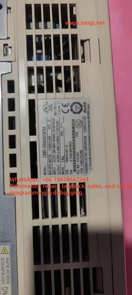
  • Contact Yaskawa support with details including model number, software version, purchase date, and fault description.

Note: In Modbus communication, if “CALL” persists, it may indicate a severe fault, potentially requiring inverter replacement as a last resort.

Preventive Measures

To reduce the likelihood of “CALL” faults, consider the following preventive actions:

  1. Regular Maintenance of Communication Lines:
    • Periodically inspect cables and terminals for damage or looseness.
    • Promptly replace aged or damaged cables.
  2. Record Communication Parameters:
    • Document all communication settings (e.g., slave address, baud rate) for quick verification and adjustment.
    • Update records after system changes or modifications.
  3. Use EMI Protection Measures:
    • Employ shielded cables and ensure proper grounding.
    • Install EMI filters or surge suppressors to reduce noise impact.
  4. Keep Firmware Updated:
    • Regularly check for firmware updates.
    • Update firmware to address known communication issues.
  5. Routine System Checks:
    • Conduct regular inspections of the inverter, master device, and communication network to identify potential issues early.
  6. Train Operating Personnel:
    • Train operators and maintenance staff on inverter operation, fault codes, and troubleshooting procedures.
    • Ensure personnel can correctly interpret “CALL” and other fault messages and take appropriate action.

Fault Code Reference Table

Below are common communication-related fault codes for the V1000 series inverters and their descriptions:

Fault CodeDescriptionPossible CausesResolution Methods
CEMEMOBUS/Modbus Communication ErrorNo response from master, parameter mismatch, wiring issuesCheck parameters, wiring, perform self-diagnostic test
bUSOption Card Communication ErrorOption card failure, wiring issues, incorrect terminal resistorCheck option card, wiring, adjust terminal resistor
CALLCommunication Wait or ErrorAwaiting communication signal, wiring/parameter issues, hardware failureCheck wiring, parameters, perform self-diagnostic, consider replacement

Conclusion

The “CALL” fault is a significant communication-related issue in Yaskawa V1000 series inverters, potentially leading to system downtime and affecting production efficiency. By inspecting wiring, verifying communication parameters, performing self-diagnostic tests, and reducing electromagnetic interference, most “CALL” faults can be resolved. Implementing preventive measures such as regular maintenance, parameter documentation, and the use of shielded cables can greatly reduce the incidence of such faults. For complex or persistent issues, consulting the Yaskawa V1000 technical manual or contacting Yaskawa technical support for professional assistance is recommended. Ensuring the reliability of the communication system is crucial for maintaining stable operation in industrial applications.

Posted on

Edwards EPX Series Vacuum Pump User Guide

Introduction

Edwards, a global leader in vacuum technology, offers the EPX series vacuum pumps, renowned for their innovative design and exceptional performance. The EPX series is a high-vacuum primary pump that integrates regenerative and Holweck stage mechanisms, enabling efficient pumping from atmospheric pressure to ultimate vacuums as low as 1 x 10^-4 mbar or 1 x 10^-5 mbar, depending on the model. This design eliminates the need for additional turbomolecular pumps in many applications, simplifying system setups.

EDWARDS EPX180L

Widely used in industries such as semiconductor manufacturing, vacuum coating, analytical instrumentation, pharmaceuticals, and optoelectronics, the EPX series excels in high-vacuum, high-cleanliness, and high-reliability applications. This guide provides a comprehensive overview of the EPX series’ performance features, applications, operational procedures, usage details, and troubleshooting methods to assist users in maximizing the pump’s potential.

1. Performance Features

The EPX series vacuum pumps are engineered for superior performance in high-vacuum environments. Below are the key technical specifications:

ParameterEPX180LEEPX180NEEPX500LEEPX500NE
Peak Pumping Speed (m³/h)175175500500
Ultimate Vacuum (mbar)<1 x 10^-4<1 x 10^-4<1 x 10^-5<1 x 10^-5
Max Exhaust Pressure (bar)0.20.200
Nitrogen Consumption (slm)025025
Cooling Water Consumption (l/h)120120120120
Supply Voltage (V)200/208/400200/208/400200/208/400200/208/400
Power at Ultimate (kW)1.41.61.41.6
Maximum Power (kW)3.03.03.03.0
Weight (kg)45474648
Inlet/Outlet ConnectionISO63/NW25ISO63/NW25ISO160/NW25ISO160/NW25
Noise (dB(A))<56<56<56<56
Vibration (mm/s, rms)<1.3<1.3<1.3<1.3
  • Pumping Speed and Vacuum: The EPX180 delivers a pumping speed of 175 m³/h, while the EPX500 achieves 500 m³/h. All models reach <1 x 10^-4 mbar, with the EPX500 capable of 1 x 10^-5 mbar due to an additional helical rotor stage.
  • Cooling System: Water cooling ensures a low environmental heat load, ideal for cleanroom settings.
  • Cleanliness: The oil- and grease-free mechanism prevents contamination, suitable for high-purity processes.
  • Nitrogen Purge: N variants (EPX180NE and EPX500NE) include a nitrogen purge facility for handling vapors and low-level corrosive gases and particulates.
  • Compact Design: Weighing approximately 45-48 kg, the EPX is smaller than equivalent turbomolecular pump and primary pump combinations.
  • Low Noise and Vibration: Noise levels below 56 dB(A) and inlet flange vibration under 1.3 mm/s ensure suitability for quiet environments.
  • Power Efficiency: Supports 200/208/400 V three-phase power, with power consumption of 1.4-1.6 kW at ultimate vacuum and a maximum of 3.0 kW.

These features position the EPX series as a high-performance solution for demanding vacuum applications.

2. Applications

The EPX series vacuum pumps are designed for a variety of high-demand applications, including:

  • High-Vacuum Processes: Ideal for applications requiring higher vacuum levels than typical primary pumps, such as semiconductor load locks, vacuum coating, and analytical instruments, where it can replace turbomolecular and primary pump combinations, reducing system complexity and cost.
  • Frequent Pressure Cycling: Suitable for processes that cycle frequently between atmospheric and low pressures, such as load locks and rapid-cycle coating systems.
  • High-Cleanliness Requirements: The oil-free design makes it perfect for pharmaceuticals, electronics, and optoelectronics, ensuring contamination-free systems.
  • Corrosive Gas Handling: The nitrogen purge facility in N variants enables handling of vapors and low-level corrosive gases, suitable for light-duty corrosive processes.

The EPX series’ versatility and efficiency make it a preferred choice in semiconductor, scientific research, and industrial production settings.

3. Operational Procedures

Proper operation of the EPX series vacuum pump is critical to ensuring performance and safety. Below are the detailed steps for operation:

3.1 Preparation and Installation

  • Installation Location: Install the pump in the vacuum system before connecting to the electrical supply to prevent accidental operation during setup, which could cause injury or equipment damage.
  • Inlet Protection: Do not remove the inlet screen or operate the pump with the inlet exposed. If hazardous substances are involved, isolate the pump from the atmosphere and process system.
  • Piping Connections: Connect the pump inlet to the process system using flexible connections to minimize vibration and stress. Use short pipes with an inner diameter no smaller than the pump inlet. Remove the inlet flange protective cap before installation and use an Edwards centering O-ring and claw clamps to seal the connection.

3.2 Connections

  • Cooling Water: Connect the cooling water supply and return lines via customer-specified water connectors (refer to Figure 2, items 4 and 9). Ensure cooling water meets environmental conditions (humidity and temperature, refer to Table 5).
  • Power Supply: Connect the electrical supply through a suitable fuse/isolator, ensuring proper grounding via the protective earth stud (Figure 2, item 3) in compliance with local electrical codes.
  • Control Interface: Connect external control equipment via the Tool Interface Module (TIM) or End User Controller (EUC). The EPX L, N, and NE series use the EUC for local and network control, while the EPX E series supports manual operation via EUC or PDT.

3.3 Starting the Pump

  • Use the run button on the EUC (Figure 7, item 1) to start the pump. The run LED (green) illuminates when the pump is operating normally.
  • For EPX N series pumps, supply nitrogen purge gas through a 1/4-inch compression fitting labeled “N2 Inlet” using 1/4-inch OD tubing, ensuring stable flow (refer to Table 10).

3.4 Monitoring and Control

  • Status Monitoring: Monitor pump status via front panel LEDs (refer to Table 1 and Figure 4):
    • Power LED (Green): Indicates main power supply is active.
    • Run LED (Green): Steady when running, flashing in idle mode.
    • Warning LED (Amber, EPX N only): Indicates low nitrogen flow.
    • Alarm LED (Red): Indicates shutdown due to a fault.
  • Control Options: Use the EUC or PDT menus (Normal, Status, Control, Setup) to check status, adjust controls, and configure parameters. The EUC display provides two-line, 16-character pump status information.

3.5 Stopping the Pump

  • Use the stop button on the EUC (Figure 7, item 10) to stop the pump.
  • In emergencies, connect to an emergency stop circuit to disconnect power immediately, requiring a separate start or reset action.

Precautions

  • Ensure proper grounding to prevent electrical hazards.
  • Verify cooling water supply meets requirements to avoid overheating.
  • For EPX N series, regularly confirm the nitrogen purge system is functioning correctly.

4. Usage Details

The EPX series vacuum pumps offer detailed operational features covering their operating range, variant functionalities, and protective mechanisms:

  • Operating Range: The pumps operate from atmospheric pressure to ultimate vacuum without lubricating or sealing fluids in the pumping chamber, ensuring a clean system with no oil back-migration.
  • Variants and Applications:
    • EPX L: Designed for clean tasks (e.g., load locks), supports local and network control via EUC.
    • EPX N: Equipped with a gas module for nitrogen purging, suitable for light-duty applications with diluted process gases.
    • EPX NE: Light-duty application pump with network and local control.
    • EPX E: Supports manual operation via EUC or PDT, ideal for network-controlled setups.
  • Capacity and Configuration: Available in 180 m³/h (EPX180LE/NE) and 500 m³/h (EPX500LE/NE) capacities, with voltage options of 200/208 V or 400 V, and water connector options of 1/4, 3/8, or 9/16-inch BSP or no quick connects.
  • Cooling System: Integrated water cooling circuit suits cleanroom environments, avoiding the drawbacks of fan cooling.
  • Performance Optimization: The EPX Twin offers enhanced performance between 1 bar and 0.2 mbar, ideal for load locks and rapid cycling applications.
  • Protective Mechanisms: Equipped with sensors like thermal cut-off switches to detect overheating and trigger automatic shutdowns. The EPX N series includes a nitrogen purge flow switch (set to 12 slm) to monitor flow.
EDWARDS EPX180NE

5. Troubleshooting

Below are common issues with the EPX series vacuum pumps and their solutions:

IssuePossible CauseSolution
Pump Shutdown (Alarm LED On)Overheating, drive faultCool the pump for at least 20 minutes, check cooling water supply (Section 2.4), restart.
Low Nitrogen Flow (Warning LED On)Insufficient nitrogen supplyVerify nitrogen flow to the gas module; if persistent, contact Edwards service center.
Noise on RestartRapid reapplication of run signalAllow the pump to fully stop before reapplying the run signal; noise is harmless.
Connection IssuesIncorrect control equipment connectionsVerify interface connections (Section 3.11); if persistent, contact Edwards service center.

Safety and Maintenance

  • Electrical Safety: Do not operate without proper grounding or correct electrical connections. The pump contains no user-serviceable parts; maintenance must be performed by Edwards professionals, with power disconnected for at least 4 minutes before removing covers.
  • Pump Seizure: If the pump seizes, wear gloves, eye protection, and a face mask due to potential aluminum sulfate dust and sulfurous odors.
  • Service Support: Contact Edwards service centers for repairs, spares, or accessories, providing model, serial number, and part details. Returns require a completed HS2 contamination form.

6. Conclusion

The Edwards EPX series vacuum pumps offer outstanding performance, versatility, and reliability for high-vacuum applications. Their oil-free design, high pumping speeds, and nitrogen purge capabilities make them ideal for semiconductor, pharmaceutical, and research industries. By following proper operational procedures, regular monitoring, and timely maintenance.

Posted on

Comprehensive User Guide for Jintech JTE280 Series Variable Frequency Drive (VFD)

I. Control Panel Operations and Parameter Management

1. Panel Interface Fundamentals

The JTE280 features two panel configurations (Fig.4-1/4-2) with essential controls:

  • RUN: Start operation (requires P0.03=0)
  • REV/JOG: Reverse/Jog (configured via P3.52)
  • STOP/RESET: Halt/Reset faults
  • PRGM: Access parameters (5-sec hold locks keyboard)
  • ▲/▼: Adjust values (real-time speed adjustment)
  • <<: Toggle monitoring parameters (J-00~J-11)

2. Factory Reset Procedure

Execute through hierarchical menu:

graph TD
    A[Press PRGM] --> B[Locate P3.01]
    B --> C[Set tens-digit=1 for default]
    C --> D[Confirm with DATA]
    D --> E[Set tens-digit=2 to clear faults]

3. Security Configuration

  • Password Protection: Set P0.00 (0001-9999)
  • Access Levels (P3.01 units-digit):
  • 0: Full access
  • 1: Only P3.01 adjustable
  • 2: Only P0.02+P3.01 adjustable
  • Keyboard Lock: 5-sec PRGM hold

II. External Control Implementation

1. Terminal-Based Motor Control

Critical Parameters:

P0.03 = 1      ; Terminal control mode
P4.08 = 0      ; 2-wire control scheme 1

Wiring Specification:

  • Forward: FWD-DCM short
  • Reverse: REV-DCM short
  • Stop: Open circuit

2. External Potentiometer Configuration

Parameter Chain:

P0.01 = 0      ; Potentiometer mode
P1.01 = 1.00   ; VI gain default
P1.02 = 0.00V  ; Min voltage
P1.05 = 50.00Hz; Max frequency

Connection Protocol:

  1. Potentiometer wiper → VI terminal
  2. Potentiometer V+ → +10V terminal
  3. Potentiometer V- → ACM terminal

Recommended: 10kΩ linear potentiometer

280-A

III. Fault Diagnosis Matrix

CodeDescriptionRoot CausesCorrective Actions
E-01Acceleration OCLoad surge/short acc.timeIncrease P0.17, inspect mechanics
E-02Deceleration OCRegenerative energyEnable P5.02 overvoltage stall
E-11DC Bus UnderVInput <305VVerify supply, set P5.07=1
E-12DC Bus OverVRapid decelerationAdjust braking parameters
E-15IGBT OverheatCooling failureClean vents, reduce loading

Troubleshooting Flow:

  1. Resolve hardware issues
  2. Press STOP/RESET to clear
  3. Analyze history (P6.00-P6.11)

IV. Advanced Application Techniques

1. Multi-Speed Programming

P4.00=1  # M11=Speed-bit1
P4.01=2  # M12=Speed-bit2
# Speed1: M11 ON
# Speed2: M12 ON
# Speed3: M11+M12 ON

2. Winding Control (Textile Applications)

P9.00=1      ; Enable wobble
P9.04=10.0%  ; Amplitude
P9.06=5.0s   ; Cycle time

3. PID Pressure Regulation

P7.00=1      ; Enable PID
P7.10=0.85   ; Proportional gain
P7.16=25.00  ; Preset frequency
JTE280

Key Operational Notes:

  1. High-altitude (>1000m) requires derating (Fig.1-3)
  2. Long cables (>30m) mandate output reactors (Sec.1.3.8)
  3. Braking resistors must comply with Table 3-25 specifications

This guide synthesizes critical operational knowledge from the 117-page manual. For complete technical specifications, refer to Chapter 9 (Application Examples) and Appendix (MODBUS protocols). Proper implementation of these procedures will optimize drive performance while ensuring operational safety.

Posted on

Delta MS300 Inverter CP30 Fault Analysis and Solutions

Introduction

Delta MS300 series inverters are widely used in industrial fields due to their high performance and reliability. However, various faults may occur during use. Among them, CP30 fault (internal communication abnormality) is a relatively common fault. This article will systematically analyze the causes, troubleshooting methods, and solutions of CP30 faults based on official materials and actual cases, helping engineers quickly locate problems and restore equipment operation.

CP30

I. Definition and Mechanism of CP30 Fault

1.1 Official Definition

According to Delta’s official technical documents, CP30 is a dedicated error code for internal communication of MS300 series inverters, indicating a communication interruption or signal delay between the control board and the drive board. This fault is usually related to abnormal hardware connections, power fluctuations, or component aging.

1.2 Fault Trigger Scenarios

  • Intermittent Fault: The equipment suddenly reports an error after running for a period of time. It temporarily recovers after restarting, but the fault recurs repeatedly.
  • After Environmental Changes: Such as restarting after holidays or when there are significant changes in ambient temperature and humidity.
  • During Load Fluctuations: Load mutations or frequent starts and stops increase communication pressure.

1.3 Fault Mechanism

The core mechanism of the CP30 fault lies in abnormal data interaction between the control board and the drive board, which may be caused by the following reasons:

  1. Hardware Connection Issues:
    • Loose or oxidized wiring at the control terminal block.
    • Communication cables longer than 15 meters without signal repeaters.
    • Power lines and control lines not laid in separate layers, causing electromagnetic interference.
  2. Power Fluctuations:
    • The 5V/12V output voltage of the switching power supply fluctuates beyond ±5%, leading to unstable power supply for the control board.
    • Harmonic interference or voltage mutations in the input power.
  3. Component Aging:
    • RS485 communication chip failure on the main control board.
    • EEPROM memory damage or degradation of optocoupler devices (such as PC923, PC929).
  4. Software and Parameters:
    • Incompatible firmware versions or incorrect parameter configurations.
    • Communication protocol settings not matching the upper computer.
MS300

II. Troubleshooting Process for CP30 Fault

2.1 Preliminary Inspection

2.1.1 Appearance and Wiring Inspection

  1. Control Terminal Block:
    • Check if the wiring is loose or oxidized, focusing on communication terminals (such as RS485 interfaces).
    • Ensure that the shielding layer of the cable is grounded at one end to avoid grounding loop interference.
  2. Communication Cables:
    • Measure the cable length. If it exceeds 15 meters, install a signal repeater.
    • Check if the cable insulation layer is damaged to avoid short circuits or crosstalk.
  3. Layered Wiring:
    • Ensure that power lines (main circuits) and control lines (signal lines) are laid separately with a spacing of at least 30cm.

2.1.2 Power and Grounding Inspection

  1. Switching Power Supply Test:
    • Use a multimeter to measure the control board power supply voltage (5V/12V). The fluctuation should be ≤±5%.
    • If the voltage is abnormal, check if the filter capacitor is aging or replace the switching power supply module.
  2. Grounding Verification:
    • Confirm that the grounding terminal is reliably connected and the grounding resistance is ≤4Ω.
    • Avoid sharing ground wires with power lines to prevent ground wire interference.

2.2 In-depth Hardware Detection

2.2.1 Circuit Board Inspection

  1. Connector Status:
    • Disassemble the inverter and observe if the connectors between the main control board and the drive board are offset, broken, or oxidized.
    • Clean the connectors and re-plug them to ensure good contact.
  2. Capacitor and Optocoupler Detection:
    • Measure the capacitance value of the main circuit filter capacitor. If it is below 80% of the rated value, replace it.
    • Use an oscilloscope to detect the input and output waveforms of optocoupler devices (such as PC923, PC929) to confirm there is no distortion or delay.

2.2.2 Communication Chip Test

  1. RS485 Chip Detection:
    • Use a multimeter to measure the voltage difference between the A and B lines of the RS485 chip. The normal value should be 2-3V.
    • If the voltage is abnormal, replace the RS485 communication chip or the control board.
  2. EEPROM Verification:
    • Test the EEPROM by initializing the inverter parameters (retain motor nameplate data).
    • If the fault persists after initialization, replace the control board.

2.3 Software and Parameter Inspection

  1. Parameter Initialization:
    • Restore the inverter to factory settings and re-enter motor parameters (such as power, number of poles, rated current, etc.).
    • Confirm that parameters 06-17~06-22 (communication-related parameters) are set correctly.
  2. Firmware Version Check:
    • Contact Delta or check the firmware version through the inverter panel.
    • If the version is too old, upgrade to the latest version to fix potential communication vulnerabilities.
  3. Communication Protocol Verification:
    • Confirm that the communication protocol (such as Modbus, CANopen) of the upper computer (such as PLC, touch screen) matches the inverter settings.
    • Use a serial debugging tool to simulate communication and verify if data interaction is normal.

III. Solutions for CP30 Fault

3.1 Hardware Repair

  1. Wiring Optimization:
    • Replace oxidized or loose wiring terminals and use tinned copper wires with crimped terminals.
    • Install signal repeaters or use shielded twisted pairs to improve communication stability.
  2. Component Replacement:
    • Replace aging capacitors, optocouplers, or RS485 chips.
    • If the control board is damaged, contact Delta for original replacement boards.
  3. Power Supply Improvement:
    • Install three-phase reactors or harmonic filters to suppress input power harmonics.
    • Replace with high-precision switching power supply modules to ensure stable power supply.

3.2 Software Adjustment

  1. Parameter Optimization:
    • Adjust the communication timeout time (parameters 14-70~14-73) and extend it appropriately to adapt to complex environments.
    • Disable unnecessary communication functions to reduce data interaction.
  2. Firmware Upgrade:
    • Download the latest firmware from Delta’s official website and upgrade the control board with a dedicated programmer.
  3. Protocol Adaptation:
    • Modify the upper computer program to ensure that the communication instruction format is compatible with the inverter.
    • Use intermediate devices (such as gateways) to convert different communication protocols.

3.3 Preventive Measures

  1. Regular Maintenance:
    • Check the tightness of wiring terminals quarterly and clean dust on circuit boards.
    • Test capacitor values and optocoupler performance annually, and replace aging components in advance.
  2. Environmental Optimization:
    • Ensure that the inverter is installed in a well-ventilated environment to avoid high temperature, high humidity, or dust pollution.
    • Keep away from high-power equipment or electromagnetic interference sources, and install shielding covers if necessary.
  3. Backup and Monitoring:
    • Regularly back up inverter parameters for quick recovery in case of faults.
    • Install communication status monitoring modules for real-time abnormality alerts.

IV. Typical Case Analysis

Case 1: Intermittent CP30 Fault

Phenomenon: An MS300 inverter in a factory frequently reported CP30 after holidays. It temporarily operated normally after restarting but failed again after a few hours.
Troubleshooting Process:

  1. Checked the control terminal block and found severe oxidation of the wiring, increasing contact resistance.
  2. Measured the communication cable length as 20 meters without a repeater, causing significant signal attenuation.
  3. Disassembled the inverter and found oxidation on the pins of the RS485 chip on the main control board, with distorted communication waveforms.
    Solution:
  4. Cleaned and tightened the wiring terminals and replaced oxidized cables.
  5. Installed a signal repeater to shorten the effective communication distance.
  6. Replaced the RS485 chip to restore communication stability.
    Result: The fault was completely eliminated, and the equipment operated normally for 3 months.

Case 2: CP30 Fault Caused by Parameter Configuration

Phenomenon: A newly installed MS300 inverter frequently reported CP30 during commissioning, but no hardware abnormalities were found.
Troubleshooting Process:

  1. Found that the engineer mistakenly set the communication timeout time to an extremely short value, causing data interaction interruption.
  2. The firmware version was too old, with communication protocol compatibility issues.
    Solution:
  3. Adjusted the communication timeout time to the default value and optimized other communication parameters.
  4. Upgraded the firmware to the latest version to fix protocol vulnerabilities.
    Result: The fault was immediately eliminated, and the equipment was successfully put into operation.

V. Conclusion

The CP30 fault is a relatively complex internal communication abnormality in Delta MS300 inverters, requiring systematic troubleshooting from multiple dimensions such as hardware connections, power quality, component aging, and software configurations. By standardizing wiring, conducting regular maintenance, optimizing parameters, and replacing components, such faults can be effectively solved. Engineers should combine official materials with actual cases, flexibly use detection tools, and gradually narrow down the fault scope to achieve rapid repair.

Posted on

In-Depth Analysis and Troubleshooting Guide for E017 Contactor Fault in Shengchuan S350 Inverter

1. Introduction: Background and Importance of the Fault

In industrial automation systems, inverters play a vital role in controlling motor speed, improving energy efficiency, and enabling flexible control. The Shengchuan S350 series inverter is widely used in automated production lines due to its high performance and reliability. However, when the inverter displays error code E017, it usually results in a startup failure or shutdown, which can seriously impact production continuity. Understanding the real cause behind the E017 alarm, distinguishing it from misinterpretations, and knowing how to troubleshoot it efficiently are crucial for technicians and maintenance engineers.


E017
_cuva

2. Understanding the E017 Fault Code

2.1 What Does E017 Mean?

In the Shengchuan S350 inverter, E017 is defined as a contactor fault, which occurs when the internal main circuit contactor (often the pre-charging or main contactor) fails to engage or the feedback signal is missing during power-up or start-up phases.

2.2 Misinterpretation in Some Manuals

Some manuals may mistakenly describe E017 as a “keypad fault.” However, in actual on-site scenarios and based on electrical logic and signal paths, this alarm is clearly linked to internal contactor failures, not the keypad (HMI) panel.


3. Causes of E017 Fault – Multi-dimensional Analysis

Type of CauseSpecific IssuesField Symptoms & Hints
Contactor ComponentCoil damage, oxidized or welded contactsNo clicking sound during start-up; blackened contacts
Drive Signal FailureNo output signal from control or drive boardNo control voltage present at coil terminals
Feedback Circuit IssueFeedback contact not closing or faultyContactor works, but inverter doesn’t recognize it
Power Supply InstabilityLow voltage, failing power boardInsufficient coil voltage to energize contactor
Control Logic MisjudgeIncorrect sequence or parameter settingsInverter fails to detect correct engagement logic

4. Step-by-Step Troubleshooting Procedure

4.1 Listen for Sound and Check Contactor Action

  • Upon power-up or start, is there a clicking sound (“clack”) from the contactor?
  • If no sound is heard, the contactor might not be energized or is physically damaged.

4.2 Measure Coil Voltage

  • Use a multimeter to check whether the contactor coil receives the control voltage (usually DC 24V or AC 220V).
  • If no voltage is detected, the issue is likely with the drive board or control signal.

4.3 Check Feedback Contact Integrity

  • Some inverters monitor auxiliary contacts on the contactor for feedback.
  • If the auxiliary contact is damaged or misaligned, even a working contactor may trigger E017.

4.4 Swap and Compare Boards

  • If you have another working S350 inverter, try swapping the contactor or drive board.
  • If the fault moves with the board, it’s likely a board-level issue. If it stays, the contactor is to blame.

S350
_cuva

5. Repair and Replacement Recommendations

5.1 Replace the Contactor

  • The most effective solution is to replace the faulty contactor with a manufacturer-approved component matching the same coil voltage and rated current.
  • Ensure proper tightening of terminals and clean installation surface.

5.2 Drive Board and Power Board Check

  • If the contactor has no drive signal, check if the relay or transistor circuit on the drive board is faulty.
  • A failing power supply board may output unstable voltage and should be checked or replaced.

5.3 Wiring and Signal Feedback

  • Verify all wiring is tight, corrosion-free, and correctly routed.
  • Clean and reconnect feedback lines if necessary.

5.4 Parameter Initialization and Reset

  • After component replacement, perform a full reset of the inverter and reconfigure necessary startup parameters.
  • Check if the inverter correctly recognizes contactor engagement signals.

6. Practical Case Studies

Case 1: Drive Board Failure

A technician encounters E017 on an S350 inverter. No clicking sound is heard on power-up. Measuring the coil terminal reveals 0V. After swapping the drive board with one from a working unit, the contactor clicks and the inverter starts normally. Conclusion: the original drive board failed to output the control signal.

Case 2: Feedback Contact Issue

Another unit shows E017 but the contactor does engage. Closer inspection shows the auxiliary feedback contact did not close properly due to carbon build-up. Cleaning restored function, but to ensure long-term reliability, the contactor was later replaced.


7. Preventive Maintenance Tips

  1. Regularly Clean Contactors
    Prevent dust, moisture, and carbon buildup from interfering with mechanical motion or electrical contact.
  2. Monitor Power Supply Quality
    Ensure stable voltage supply to the control board and contactor coil to prevent intermittent faults.
  3. Log Faults and Spare Part Info
    Keep a history of faults and maintain a stock of critical spares such as contactors, drive boards, and power boards.
  4. Perform Routine Start-Up Tests
    Periodically run the inverter in test mode to check for early signs of engagement or feedback failure.

8. Summary and Conclusions

  • The E017 error code in the Shengchuan S350 inverter most accurately refers to an internal contactor failure, not a keypad issue.
  • Diagnosing the fault involves confirming whether the contactor actuates, checking for control voltage, and verifying feedback signal integrity.
  • Most common causes include faulty contactors, failed drive boards, or broken feedback circuits.
  • Effective troubleshooting requires listening for sounds, using a multimeter for voltage checks, and replacing components as needed.
  • Preventive maintenance and spare part readiness are essential to avoid prolonged downtime in industrial systems.

Posted on

Understanding and Resolving the E-09 Undervoltage Fault in Shenzhen Tai Da V680 Series Variable Frequency Drives

Introduction

Variable frequency drives (VFDs) are critical components in industrial automation, enabling precise control of motor speed and torque to enhance efficiency and performance. The V680 series VFD, produced by Shenzhen Tai Da Holdings, is a high-performance model widely used in applications such as manufacturing, HVAC systems, and conveyor operations. However, like all sophisticated electronic devices, it may encounter faults that disrupt operations. One common issue is the “E-09” fault code, which indicates an undervoltage condition. This article provides a comprehensive analysis of the E-09 fault’s mechanisms, implications, diagnostic procedures, solutions, and preventive strategies, drawing from technical insights and industry resources.

E-09

Technical Background of the V680 Series VFD

Role of VFDs

VFDs regulate the speed and torque of AC motors by adjusting the frequency and voltage of the power supplied. This capability optimizes energy consumption, reduces mechanical stress, and enhances process control in industrial settings. The V680 series, with its advanced vector control algorithms, is designed for demanding applications requiring high reliability and precision.

V680 Series Specifications

Based on available information, the V680 series (model: SHZHD.V680-55KW/75KWP-3) has the following key specifications:

ParameterSpecification
Input3-phase, 380V ±15%, 50Hz
Output3-phase, 112/150A, 0-500Hz
PowerG-55kW
ManufacturerShenzhen Tai Da Holdings Co., Ltd.

The input voltage range of 323V to 437V is critical for understanding the E-09 fault, as voltages below 323V trigger undervoltage protection.

Definition and Implications of the E-09 Undervoltage Fault

Definition

The E-09 fault code signifies that the VFD’s input voltage has fallen below the minimum threshold required for safe operation, typically around 323V for a 380V system. This undervoltage condition prompts the VFD to halt operation to protect itself and the connected motor, displaying “E-09” on the control panel.

Implications

The E-09 fault can have significant consequences:

  • Operational Downtime: The VFD’s shutdown halts motor operation, disrupting production processes and potentially causing financial losses in industries reliant on continuous operation.
  • Component Wear: Prolonged undervoltage can stress electrolytic capacitors and other components, reducing their lifespan and increasing maintenance costs.
  • Performance Issues: In applications requiring precise motor control, such as conveyor systems, undervoltage may lead to erratic motor behavior, compromising product quality.

Mechanisms Behind the E-09 Undervoltage Fault

VFD Operational Principles

A VFD converts input AC power to DC through a rectifier, stores it in a DC bus with capacitors, and then inverts it back to AC with adjustable frequency and voltage to drive the motor. The DC bus voltage, typically around 520V for a 380V input, is crucial for stable operation. A drop in input voltage reduces the DC bus voltage, triggering the E-09 fault if it falls below the undervoltage threshold (approximately 60% of nominal, or ~312V DC).

Causes of Undervoltage

The E-09 fault may result from several factors:

  1. External Power Supply Instability:
    • Grid Fluctuations: Variations in the utility power supply, such as voltage sags or outages, can lower the input voltage.
    • Heavy Load Demands: Simultaneous operation of high-power equipment may cause voltage drops.
    • Phase Loss: Loss of one phase in a three-phase system increases DC bus ripple and may trigger undervoltage protection.
  2. Internal Component Failures:
    • Capacitor Degradation: Electrolytic capacitors in the DC bus may lose capacity over time, failing to smooth voltage fluctuations.
    • Rectifier Issues: Damaged diodes or rectifiers in the power conversion circuit can impair voltage regulation.
    • Pre-Charge Circuit Problems: Faulty pre-charge relays or resistors can prevent proper DC bus charging, especially during startup.
  3. Wiring and Connection Issues:
    • Loose or corroded connections increase resistance, causing voltage drops at the VFD’s input.
    • Improper wiring, as outlined in the V680 manual’s connection diagrams, can exacerbate the issue.
  4. Environmental Factors:
    • High temperatures or humidity can degrade component performance, indirectly contributing to undervoltage.
    • Dust accumulation may cause overheating or short circuits, affecting voltage stability.
  5. Sensing Circuit Malfunction:
    • A faulty DC voltage sensing circuit within the VFD may incorrectly detect low voltage, causing nuisance trips.

Trigger Mechanism

The VFD continuously monitors the DC bus voltage. When it detects a voltage below the undervoltage threshold, it activates the E-09 fault, halting operation. For the V680 series, this threshold is likely set to protect against voltages below 323V AC, corresponding to a DC bus voltage of approximately 312V. The fault may reset automatically after 5 seconds if the voltage stabilizes, as noted in some Tai Da VFD documentation.

Diagnostic Steps for the E-09 Fault

Diagnosing the E-09 fault requires a systematic approach to identify the root cause:

  1. Verify Input Voltage:
    • Measure the input voltage at the VFD’s terminals using a multimeter, ensuring it is within 380V ±15% (323V–437V).
    • Check all three phases for balance and absence of phase loss.
    • If the voltage is low, investigate upstream power supply issues with the utility provider.
  2. Inspect Internal Components:
    • Power down the VFD and inspect for visible signs of damage, such as capacitor leakage, bulging, or burn marks on the rectifier or control board.
    • Test capacitors and rectifiers with appropriate equipment, if qualified, or consult a technician.
    • Check the pre-charge circuit for relay or resistor functionality.
  3. Examine Wiring and Connections:
    • Refer to the V680 manual’s wiring diagrams to verify correct connections.
    • Tighten all terminal connections and inspect cables for damage or corrosion.
  4. Evaluate Environmental Conditions:
    • Ensure the VFD operates within the recommended temperature (-10°C to +40°C) and humidity (≤95% RH, non-condensing) ranges.
    • Clean dust from the VFD and improve ventilation if necessary.
  5. Review Control Panel Diagnostics:
    • Note any additional indicators on the control panel, such as “Hz” or “RUN” status, to contextualize the fault.
    • Cross-reference the E-09 code with the manual’s fault table, if available, for specific guidance.
  6. Test DC Bus Voltage:
    • If equipped, measure the DC bus voltage to confirm it aligns with the expected value (~520V for 380V input). Discrepancies may indicate internal issues or sensing circuit faults.

Solutions to Resolve the E-09 Undervoltage Fault

Immediate Corrective Actions

  1. Reset the Fault:
    • Power cycle the VFD by turning off the main supply, waiting a few minutes, and restarting. Alternatively, use the control panel’s reset function.
    • Verify if the fault clears after voltage stabilization.
  2. Address Power Supply Issues:
    • Install a voltage stabilizer or uninterruptible power supply (UPS) to maintain consistent 380V input.
    • Use a line reactor or isolation transformer to mitigate voltage sags and surges.
    • Coordinate with the utility provider to adjust transformer tap settings or resolve grid issues.
  3. Repair Internal Components:
    • Replace faulty capacitors, rectifiers, or pre-charge circuit components, adhering to the manual’s maintenance guidelines and using manufacturer-approved parts.
    • Engage a qualified technician for complex repairs to avoid further damage.
  4. Correct Wiring Issues:
    • Tighten loose connections and replace damaged cables as per the manual’s wiring specifications.
    • Ensure proper grounding to prevent electrical interference.
  5. Mitigate Environmental Factors:
    • Relocate the VFD to a cooler, drier location or enhance ventilation with fans or air conditioning.
    • Install dust filters to protect internal components.

Long-Term Preventive Measures

  1. Regular Maintenance:
    • Schedule monthly or quarterly inspections to check wiring, components, and cleanliness, as recommended in the V680 manual.
    • Monitor capacitor health and replace them proactively based on their rated lifespan.
  2. Power Protection Systems:
    • Deploy surge protectors, phase loss relays, and dynamic voltage restorers to safeguard against power anomalies.
    • Consider a static var compensator for facilities with frequent voltage sags.
  3. Environmental Optimization:
    • Maintain a controlled environment with stable temperature and humidity levels.
    • Enclose the VFD in a protective cabinet if exposed to harsh conditions.
  4. Operator Training:
    • Train personnel to recognize E-09 and other fault codes, enabling quick initial responses.
    • Provide access to the V680 manual for reference during troubleshooting.
  5. Manufacturer Support:
    • Establish a relationship with Shenzhen Tai Da Holdings’ customer service for technical support and access to firmware updates or replacement parts.
SHZHD.V680

Comparison with Other VFD Faults

To contextualize the E-09 fault, consider other common VFD faults:

Fault CodeDescriptionCommon Causes
E-10OvervoltageExcessive input voltage, regenerative energy
E-06OvercurrentMotor overload, short circuit
E-04OverheatingPoor ventilation, high ambient temperature
E-07Ground FaultMotor or wiring insulation failure

While E-09 is specific to undervoltage, its diagnostic and resolution strategies overlap with these faults, particularly in checking power supply and environmental conditions.

Additional Insights from Industry Resources

Research indicates that undervoltage faults, like E-09, are common in VFDs due to their sensitivity to power quality. , undervoltage protection is typically based on DC bus voltage, which for a 380V system should be around 520V. A drop to 60% of this value (~312V) triggers the fault. The site also highlights phase loss as a frequent cause.

Troubleshooting Flowchart

Below is a simplified flowchart for addressing the E-09 fault:

Start
  ↓
Check Input Voltage (380V ±15%)
  ↓
Voltage Normal? → Yes → Inspect Internal Components
  ↓ No
Adjust Power Supply (Stabilizer/UPS)
  ↓
Fault Cleared? → Yes → End
  ↓ No
Inspect Wiring/Connections
  ↓
Connections Secure? → Yes → Check Environment
  ↓ No
Tighten/Replace Wiring
  ↓
Environment Normal? → Yes → Reset Fault
  ↓ No
Improve Ventilation/Cleanliness
  ↓
Fault Cleared? → Yes → End
  ↓ No
Contact Manufacturer Support

Conclusion and Best Practices

The E-09 undervoltage fault in the V680 series VFD is a manageable issue when approached systematically. By identifying whether the cause is external power instability, internal component failure, wiring issues, or environmental factors, users can implement targeted solutions to restore operation. The V680 manual is a critical resource, providing wiring diagrams, safety guidelines, and maintenance protocols to support troubleshooting.

Best practices include:

  • Stable Power Supply: Use voltage stabilizers and UPS systems to ensure consistent 380V input.
  • Routine Maintenance: Conduct regular inspections to detect and address component wear early.
  • Environmental Control: Maintain optimal operating conditions to protect the VFD.
  • Operator Training: Equip staff with the knowledge to respond to fault codes promptly.
  • Manufacturer Support: Leverage Shenzhen Tai Da Holdings’ expertise for complex issues.

By adopting these strategies, users can minimize downtime, extend the VFD’s lifespan, and ensure reliable performance in industrial applications. This comprehensive approach not only resolves the E-09 fault but also enhances overall system resilience against future power-related issues.

Posted on

V&T VY-JY Injection Molding Machine Dedicated Asynchronous Servo Drive User Guide

I. Product Overview and Core Advantages

1. Product Positioning

The VY-JY series is a high-performance asynchronous servo drive specifically designed for the hydraulic systems of injection molding machines. It employs sensorless vector control technology to adjust the speed of the oil pump motor to match the flow/pressure requirements of the injection molding process, eliminating overflow energy consumption and achieving a 25%-70% energy savings rate.

2. Technical Highlights

Dual Vector Control Modes:

  • Vector Control 1: 180% starting torque at 0.50 Hz, speed regulation range of 1:100, and speed stability accuracy of ±0.5%.
  • Vector Control 2: 180% starting torque at 0.25 Hz, speed regulation range of 1:200, and speed stability accuracy of ±0.2% (comparable to DC motor control).

Core Energy-Saving Technologies for Injection Molding:

  • Real-time reception of injection molding machine pressure/flow signals to dynamically adjust oil pump speed, eliminating high-pressure overflow losses.
  • Support for 3 customizable flow-pressure curves (4-point, 5-segment correction) to adapt to different mold processes.

High Reliability Design:

  • Wide voltage range (DC 360-720V) and triple-protection technology (PCB coating, copper busbar plating, and sealed components).
  • Short-term overload capacity: 200% rated load for 0.5 seconds, 150% rated load for 1 minute.
V&T VY-JT

II. Installation and Wiring Specifications

1. Installation Environment Requirements

ParameterStandard ValueRemarks
Ambient Temperature-10°C to +40°CDerate rated current by 1% for every 1°C increase above 40°C
Humidity5% to 95%Condensation prohibited
Altitude≤2000 metersDerate by 1% for every 100 meters above 1000 meters
Vibration≤15 m/s² (200-500 Hz)Avoid metal dust/corrosive gases

2. Main Circuit Wiring Essentials

  • Power Terminals: Connect R/L1, S/L2, and T/L3 to a three-phase power supply (380-480V ±15%).
  • Motor Terminals: Connect U/T1, V/T2, and W/T3 to the motor. Reverse connection or short-circuiting is strictly prohibited.
  • Brake Resistor:
    • Models from 11-15 kW come with a built-in brake unit (terminals B1/B2) as standard.
    • Models above 18.5 kW require an optional brake resistor with a resistance value greater than the lower limit specified in the manual (e.g., ≥7Ω for a 55 kW model).
  • Grounding Requirements:
    • The PE terminal must be independently grounded (resistance <10Ω).
    • The grounding wire diameter should be selected based on power rating (e.g., 35 mm² for a 90 kW model).

3. Control Circuit Wiring

  • Analog Inputs:
    • AI1/AI2: 0-10V or 0-20mA (selectable via jumpers).
    • AI3: -10V to +10V (supports direction control).
  • Digital Inputs: X1-X7 support 24VDC switch/pulse signals (up to 50 kHz).
  • Communication Interface: Dual 485 ports (Modbus-RTU protocol), supporting master-slave control and parameter reading/writing.

⚠️ Safety Warning:

  • Separate or vertically cross the main and control circuit wiring to prevent interference.
  • When the motor cable exceeds 100 meters, an output reactor must be installed, and the carrier frequency must be reduced (≤5 kHz).

III. Operation Procedures and Parameter Settings

1. Initial Power-On Operation Procedure

mermaidgraph TD    A[Power On] --> B[Restore Factory Parameters P0.01=3]    B --> C[Set Motor Nameplate Parameters P9.00-P9.04]    C --> D{Can the Load Be Disconnected?}    D -->|Yes| E[Rotating Auto-Tuning P9.15=2]    D -->|No| F[Stationary Auto-Tuning P9.15=1]    E & F --> G[Press RUN Key to Execute Auto-Tuning]    G --> H[Set Operating Frequency P0.05]    H --> I[Select Control Mode P0.03]    I --> J[Start Operation]

2. Injection Molding-Specific Function Configuration

Energy-Saving Mode Activation (H0 Group Parameters):

Function CodeNameExample SettingFunction Description
H0.00Plastic Machine Frequency Setting Mode Selection1Enable User-Defined 1
H0.03Plastic Machine Frequency Setting User-Defined 10000Both Flow and Pressure Signals Are Valid
H0.09-H0.16Flow-Frequency Curve 1A0=0%, B0=0%
A3=100%, B3=100%
4-Point Linear Mapping

Soft PLC Logic Programming (H1 Group Parameters):
Perform logical operations (AND/OR/NOT) or mathematical operations (addition, subtraction, multiplication, division) on digital/analog quantities, and output the results to the Y terminal or control frequency.
Example: H1.00=111 enables 3-channel logical operations, and H1.01=123 sets X1/X2/X3 as input sources.

3. Key Operating Parameters

Parameter GroupFunction CodeNameRecommended ValueImpact
P0P0.08Acceleration Time 020.0sExtend for large inertia loads
P3P3.05Stopping Method2 (Deceleration + DC Braking)Prevent pump reversal
PAPA.00Carrier Frequency8.0kHzReduce for high-frequency noise-sensitive applications

IV. Fault Diagnosis and Maintenance

VY-JY-4T11G

1. Common Fault Handling

Fault CodeMeaningTroubleshooting Steps
E.OC1Acceleration Overcurrent1. Check for motor cable short-circuits.
2. Extend acceleration time.
E.OUDeceleration Overvoltage1. Check brake resistor value.
2. Enable energy dissipation braking.
E.PTCMotor Overheating1. Check PTC sensor wiring.
2. Reduce load rate.

2. Regular Maintenance Items

CycleItemOperation
MonthlyRadiator CleaningUse compressed air to remove dust (operate with power off).
Semi-AnnuallyElectrolytic Capacitor InspectionCheck for bulging/leakage; replace if capacity drops by ≥20%.
AnnuallyInsulation Resistance TestMotor winding-to-ground insulation resistance ≥5MΩ (500VDC).

🔧 Maintenance Note: Wait 10 minutes after power-off (until the CHARGE light goes out) before operating to ensure bus capacitor discharge is complete.

V. Energy-Saving Benefit Analysis

Energy Savings Rate Calculation Model:
Energy Savings Rate=(1−Servo System Energy ConsumptionPower Frequency System Energy Consumption​)×100%

Influencing Factors:

  • Mold Process Speed Value: Energy savings rate ≈70% at 30% speed and ≈25% at 90% speed.
  • Net Cooling Time: Energy savings rate decreases without cooling time.

✅ Case Study: Post-retrofit measurements for a 220T injection molding machine at a certain factory:

  • Power Frequency Monthly Energy Consumption: 18,600 kWh
  • Servo Monthly Energy Consumption: 7,440 kWh
  • Energy Savings Rate: 60%

VI. Appendix: Key Parameter Quick Reference Table

CategoryFunction CodeNameFactory Default
Motor ParametersP9.02Rated Speed1500 rpm
Communication SettingsPC.02Local Address1
Protection FunctionsPA.21Auto-Reset Count0 (Disabled)
Plastic Machine-SpecificH0.34AI1/AI2 Extended Input Enable0 (Disabled)

This guide covers the entire process of installation, parameter configuration, fault handling, and energy-saving optimization. It is compiled in conjunction with Chapter 9 (Injection Molding Energy-Saving Principles) and Chapter 10 (Technical Features) of the manual to ensure users quickly master the core applications of the VY-JY series. Before operation, be sure to read the manual’s “Safety Precautions” (Pages 14-16) in detail. Unauthorized operation is strictly prohibited.

Posted on

Rockwell PowerFlex 400 Series Inverter FAULT 008 Troubleshooting and Resolution

Key Points:

  • FAULT 008, known as “Heatsink Over Temperature,” indicates that the inverter’s heatsink temperature has exceeded safe limits, likely to protect the device from overheating damage.
  • Common causes include blocked or dirty heatsink fins, high ambient temperatures, or cooling fan failure.
  • Troubleshooting involves cleaning the heatsink, verifying ambient temperature, and checking fan operation.
  • Preventive measures include regular maintenance, temperature monitoring, and proper installation to ensure adequate airflow.

What is FAULT 008?
When a Rockwell PowerFlex 400 series inverter displays FAULT 008, labeled “Heatsink OvrTmp,” it signals that the heatsink temperature has surpassed its safe operating threshold. This fault halts the inverter to prevent damage to internal components, such as the power electronics. The control panel will show “FAULT 008 Heatsink Ovrtmp” with a yellow or orange indicator light, alerting the user to take immediate action.

fault  008

Why Does It Happen?
The overheating of the heatsink can stem from several issues:

  • Blocked or Dirty Heatsink Fins: Dust or debris accumulation reduces the heatsink’s ability to dissipate heat.
  • High Ambient Temperature: Operating environments exceeding 40°C (104°F) for IP 30/NEMA 1/UL Type 1 installations or 50°C (122°F) for open-type installations can overwhelm the cooling system.
  • Fan Failure: A malfunctioning or stopped cooling fan disrupts airflow, causing heat buildup.

How to Address It?
To resolve FAULT 008, follow these steps:

  • Clean the Heatsink: Power off the inverter, open the enclosure, and use compressed air or a soft brush to remove dust or debris from the heatsink fins.
  • Check Ambient Temperature: Measure the surrounding temperature to ensure it is within the specified limits. If too high, improve ventilation or relocate the inverter.
  • Inspect the Fan: Verify that the cooling fan is operational. Replace it if it’s not functioning, using a compatible part.

Preventing Future Issues
Regular maintenance, such as cleaning the heatsink and monitoring ambient conditions, along with proper installation to ensure good airflow, can help avoid this fault in the future.


Comprehensive Analysis and Solutions for FAULT 008 in Rockwell PowerFlex 400 Series Inverters

Introduction

The Rockwell PowerFlex 400 series inverters are widely used in industrial automation for controlling AC motor speed and torque, particularly in applications like fans and pumps. Known for their reliability and versatility, these inverters occasionally encounter faults that require prompt attention. One such fault, FAULT 008 (Heatsink Over Temperature), indicates that the inverter’s heatsink has exceeded its safe temperature threshold. This article provides a detailed exploration of FAULT 008, including its definition, causes, troubleshooting steps, solutions, and preventive measures to ensure reliable operation.

This content is based on information from the Rockwell PowerFlex 400 User Manual and fault code documentation, ensuring accuracy and relevance for users addressing this issue.

1. Understanding FAULT 008

FAULT 008, labeled “Heatsink OvrTmp,” is a critical fault in the PowerFlex 400 series that occurs when the heatsink temperature exceeds the safe operating limit. The heatsink is a vital component responsible for dissipating heat generated by the inverter’s power electronics, such as IGBT modules. When this fault is triggered, the inverter halts operation to prevent thermal damage, displaying “FAULT 008 Heatsink Ovrtmp” on the control panel with a yellow or orange indicator light. This fault is classified as an Auto-Reset/Run type, meaning it may attempt to reset automatically if configured (via parameters A092 and A093), provided the underlying issue is resolved.

2. Causes of FAULT 008

Several factors can lead to the heatsink overheating, triggering FAULT 008. The primary causes include:

2.1 Blocked or Dirty Heatsink Fins

The heatsink relies on air circulation to dissipate heat. Dust, oil, or debris accumulation on the fins can obstruct airflow, significantly reducing cooling efficiency. This is particularly common in dusty industrial environments.

2.2 High Ambient Temperature

The PowerFlex 400 has specific environmental temperature limits:

  • IP 30/NEMA 1/UL Type 1 Installations: Maximum ambient temperature of 40°C (104°F).
  • Open-Type Installations: Maximum ambient temperature of 50°C (122°F).
    If the operating environment exceeds these limits, the heatsink may struggle to maintain safe temperatures.

2.3 Cooling Fan Failure

The inverter’s cooling fan ensures adequate airflow over the heatsink. A malfunctioning fan—due to mechanical issues (e.g., worn bearings), electrical faults, or blockages—can lead to insufficient cooling and overheating.

2.4 Excessive Load or Duty Cycle

Running the inverter at or beyond its rated capacity for extended periods generates excessive heat, which the cooling system may not handle effectively.

2.5 Poor Ventilation

Improper installation, such as placing the inverter in a confined space or obstructing air inlets/outlets, can trap heat and cause the heatsink to overheat.

CauseDescriptionImpact
Blocked Heatsink FinsDust or debris reduces airflow, impairing heat dissipation.Heatsink temperature rises.
High Ambient TemperatureEnvironment exceeds 40°C (IP 30) or 50°C (Open type).Cooling system overwhelmed.
Cooling Fan FailureFan stops or operates inefficiently, reducing airflow.Inadequate heatsink cooling.
Excessive LoadProlonged high-load operation generates excessive heat.Heatsink temperature exceeds limits.
Poor VentilationRestricted airflow due to improper installation or obstructions.Heat accumulation.
powerflex 400

3. Troubleshooting FAULT 008

Resolving FAULT 008 requires a systematic approach to identify and address the root cause. Below are the recommended steps:

3.1 Inspect and Clean Heatsink Fins

  • Procedure: Disconnect the inverter from power, open the enclosure, and inspect the heatsink fins for dust, oil, or debris.
  • Tools: Use compressed air or a soft brush to clean the fins, ensuring no contaminants remain.
  • Precautions: Avoid introducing foreign objects into the inverter during cleaning.

3.2 Verify Ambient Temperature

  • Procedure: Measure the ambient temperature around the inverter using a thermometer.
  • Standards:
  • IP 30/NEMA 1/UL Type 1: ≤40°C (104°F).
  • Open Type: ≤50°C (122°F).
  • Action: If the temperature exceeds limits, enhance ventilation (e.g., add fans or air conditioning) or relocate the inverter to a cooler area.

3.3 Check Cooling Fan Operation

  • Procedure:
  • Power on the inverter and confirm the fan is running by listening for operation or checking for airflow.
  • Inspect for blockages or damage to the fan blades.
  • Listen for unusual noises indicating bearing wear or mechanical issues.
  • Action: Replace a faulty fan with a genuine Rockwell part, following the manual’s replacement instructions.

3.4 Evaluate Load and Duty Cycle

  • Procedure:
  • Check the inverter’s load to ensure it does not exceed the rated capacity.
  • Review parameter A089 [Current Limit 1] to confirm it matches the motor’s specifications.
  • Action: Reduce the load or adjust parameters if overloading is detected. Consider upgrading to a higher-capacity inverter if necessary.

3.5 Ensure Adequate Ventilation

  • Procedure:
  • Verify that the inverter has sufficient clearance (at least 10-15 cm) around air inlets and outlets.
  • Check for obstructions blocking airflow.
  • Action: Reposition the inverter or remove obstructions to improve ventilation.

4. Solutions and Preventive Measures

4.1 Solutions

Based on the troubleshooting results, apply the following solutions:

  • Dirty Heatsink Fins: Clean thoroughly to restore airflow.
  • High Ambient Temperature: Install cooling equipment or relocate the inverter.
  • Fan Failure: Replace the fan with a compatible part.
  • Excessive Load: Adjust load or parameters, or upgrade the inverter.
  • Poor Ventilation: Reconfigure the installation to ensure proper airflow.

4.2 Preventive Measures

To minimize the risk of FAULT 008 recurring, adopt these practices:

  • Regular Maintenance:
  • Clean heatsink fins and inspect fans every 3-6 months, adjusting frequency based on environmental conditions.
  • Replace aging fans proactively to avoid unexpected failures.
  • Environmental Monitoring:
  • Use temperature sensors to monitor ambient conditions and alert for exceedances.
  • Install cooling systems in high-temperature environments.
  • Load Management:
  • Ensure the inverter’s capacity matches the application’s demands.
  • Avoid prolonged operation at maximum load.
  • Proper Installation:
  • Adhere to the PowerFlex 400 User Manual’s installation guidelines, ensuring adequate clearance and ventilation.
  • Avoid enclosed or poorly ventilated spaces.

5. Conclusion

FAULT 008 (Heatsink Over Temperature) in the Rockwell PowerFlex 400 series inverters is a critical issue that requires immediate attention to prevent equipment damage. By understanding its causes—such as blocked heatsink fins, high ambient temperatures, or fan failures—users can systematically troubleshoot and resolve the fault. Implementing regular maintenance, monitoring environmental conditions, and ensuring proper installation are key to preventing recurrence. This comprehensive guide equips users with the knowledge and steps needed to maintain reliable and efficient operation of their PowerFlex 400 inverters.

Posted on

Analysis and Solution for ABB ACS580 Fault 4310 (A4B0): Power Unit Module Temperature Excessive

Introduction

Variable frequency drives (VFDs) like the ABB ACS580 are vital in industrial automation, offering precise control over motor speed and torque for applications such as pumps, fans, and conveyors. These drives enhance efficiency but can encounter faults that disrupt operations. One common issue is fault code 4310, also known as A4B0, which signals that the power unit module temperature has exceeded safe limits. This article explores the causes, mechanisms, troubleshooting steps, and preventive measures for this fault, providing a comprehensive guide for users and maintenance personnel to ensure reliable operation.

4310 FAULT

Understanding Fault 4310 (A4B0)

Fault 4310 (A4B0) in the ABB ACS580 indicates that the temperature of the power unit module, which contains insulated gate bipolar transistors (IGBTs) responsible for converting DC to AC for motor control, has become excessively high. IGBTs generate heat during operation due to switching and conduction losses. When the temperature exceeds a safe threshold (typically 90-100°C, depending on the model), the drive triggers this fault to halt operation and protect internal components from thermal damage. The fault code appears on the control panel, often with auxiliary codes indicating specific issues, such as overheating in the U, V, or W phase, or environmental factors.

Causes of Fault 4310 (A4B0)

Several factors can contribute to the power unit module overheating, including:

  1. High Ambient Temperature: The ACS580 is designed to operate in environments up to 40°C (104°F). If the surrounding temperature exceeds this, the cooling system may struggle to dissipate heat effectively, especially in enclosed or poorly ventilated spaces.
  2. Insufficient Cooling: The drive relies on cooling fans to draw air over heat sinks attached to the power modules. Fan failures due to worn bearings, electrical issues, or blocked airflow paths (e.g., by debris or improper placement) reduce cooling efficiency.
  3. Dust Accumulation: In industrial environments, dust and particulate matter can accumulate on heat sinks, acting as an insulator and hindering heat transfer. This reduces the cooling system’s effectiveness.
  4. Overloading: Operating the drive beyond its rated power capacity causes the IGBTs to generate excessive heat. This can occur if the connected motor or load exceeds the drive’s specifications.
  5. Incorrect Installation: ABB provides specific installation guidelines, including minimum clearance distances for airflow. Installing the drive in a confined space or near heat-generating equipment can trap heat, leading to overheating.

Mechanism of Fault 4310 (A4B0)

The ACS580 is equipped with temperature sensors that continuously monitor the power unit module’s temperature. These sensors are integrated into the drive’s control system, which compares the measured temperature against a predefined limit. If the temperature exceeds this threshold, the drive activates fault 4310 (A4B0) to stop operation, preventing damage to the IGBTs and other components. The fault may be accompanied by auxiliary codes that pinpoint the issue, such as specific phase overheating (U, V, or W), environmental temperature issues, or internal component failures. This protective mechanism ensures the drive’s longevity and reliability by addressing thermal risks promptly.

Troubleshooting and Solutions

To resolve fault 4310 (A4B0), follow these systematic steps:

  1. Check Ambient Temperature: Measure the temperature near the drive using a reliable thermometer. Ensure it is within the 0-40°C range specified for the ACS580. If the temperature is too high, improve ventilation by adding fans or air conditioning, or relocate the drive to a cooler area.
  2. Inspect Cooling Fans: With the drive powered off, check all cooling fans for proper operation. Look for signs of damage, loose connections, or worn bearings. Listen for unusual noises indicating fan issues. Replace faulty fans with ABB-approved components and verify that the fan direction supports proper airflow.
  3. Clear Airflow Paths: Ensure that air intake and exhaust vents are free from obstructions such as cable bundles, dust filters, or other objects. Remove any covers or panels that restrict airflow and reposition items as needed.
  4. Clean Heat Sinks: Disconnect the drive from power and use compressed air or a soft brush to remove dust and debris from the heat sinks. Avoid using liquids that could leave residues or damage components. Ensure the heat sinks are clean to maximize heat transfer.
  5. Verify Load: Compare the drive’s rated power (listed on its nameplate) with the motor’s specifications and the actual load. If the load exceeds the drive’s capacity, consider reducing the load or upgrading to a higher-capacity drive model.
  6. Review Installation: Consult the ABB ACS580 installation manual to confirm that the drive is mounted correctly. Ensure there is at least 100 mm (4 inches) of clearance on all sides for airflow. Verify that the drive is not exposed to direct sunlight or other heat sources.
  7. Reset the Drive: After addressing the above issues, reset the drive by cycling power or using the reset button on the control panel. Monitor the drive’s operation to ensure the fault does not recur. Check the event log for any additional diagnostic information.
ACS580

Troubleshooting Steps Table

StepActionNotes
Check Ambient TemperatureMeasure temperature near the driveEnsure within 0-40°C; improve ventilation if needed
Inspect Cooling FansCheck for operation, damage, or noiseReplace faulty fans; confirm correct airflow direction
Clear Airflow PathsRemove obstructions from ventsEnsure no cables or debris block intake/exhaust
Clean Heat SinksUse compressed air or brush to cleanPower off drive; avoid liquids
Verify LoadCompare drive and motor ratingsReduce load or upgrade drive if necessary
Review InstallationCheck clearance and placementEnsure 100 mm clearance; avoid heat sources
Reset DriveCycle power or use reset buttonMonitor for fault recurrence

Preventive Measures

To minimize the risk of fault 4310 (A4B0), implement these preventive strategies:

  1. Regular Maintenance Schedule: Establish a maintenance routine, inspecting and cleaning the cooling system every 6-12 months, depending on the environment’s dust levels. Regular checks prevent dust buildup and ensure fan reliability.
  2. Temperature Monitoring: Utilize the ACS580’s built-in temperature monitoring features (accessible via parameters like 04.11-04.13) to track temperature trends. Set alarms to alert personnel if temperatures approach critical levels, enabling early intervention.
  3. Load Management: Design systems with adequate headroom for peak loads. Avoid operating the drive at or near its maximum capacity for extended periods. Use energy-saving modes or adjust parameters to optimize performance for variable loads.
  4. Proper Installation Practices: Adhere to ABB’s installation guidelines, ensuring proper mounting, electrical connections, and grounding. Maintain specified clearance distances to support airflow and prevent heat buildup.
  5. Environmental Control: In harsh environments (e.g., dusty or hot locations), use NEMA-rated enclosures and maintain air filters. In high-temperature settings, consider additional cooling solutions like heat exchangers or air conditioning.

Preventive Measures Table

MeasureActionFrequency
Regular MaintenanceInspect and clean cooling systemEvery 6-12 months
Temperature MonitoringTrack temperature trends via parametersWeekly or monthly
Load ManagementEnsure load matches drive capacityDuring system design
Proper InstallationFollow ABB guidelines for mountingDuring installation
Environmental ControlUse enclosures, filters, or coolingAs needed per environment

Conclusion

Fault 4310 (A4B0) in the ABB ACS580, indicating excessive power unit module temperature, is a critical issue that demands prompt attention to prevent damage to the drive. By understanding its causes—such as high ambient temperatures, cooling failures, dust accumulation, overloading, or improper installation—users can follow systematic troubleshooting steps to resolve the issue. Preventive measures, including regular maintenance, temperature monitoring, load management, and proper installation, are essential for minimizing the risk of recurrence. Familiarity with the drive’s documentation, such as the user manual and fault tracing guide, and ongoing training for maintenance personnel further enhance operational reliability. By addressing this fault effectively, users can ensure the ACS580 operates efficiently, supporting uninterrupted industrial processes.

Posted on

Fault Analysis and Solutions for SPO Fault in Yuqiang Frequency Converter YQ3000-G11

Introduction

In industrial automation and control systems, Variable Frequency Drives (VFDs) are indispensable core devices. They convert fixed-frequency AC power into variable-frequency AC power, enabling precise control over the speed and torque of AC motors. This functionality is crucial in various fields, including manufacturing, Heating, Ventilation, and Air Conditioning (HVAC), and water pump systems. The Yuqiang YQ3000-G11 frequency converter, manufactured by Foshan Yuqiang Electromechanical Co., Ltd., is widely popular in the market for its reliability and high performance. However, like any electronic device, it may encounter faults, with the SPO fault (Output Phase Loss) being one of the common issues faced by YQ3000-G11 users. This article delves into the nature, causes, solutions, and preventive measures of the SPO fault, providing comprehensive guidance to ensure efficient and stable system operation.

FAULT SPO

Definition and Manifestation of SPO Fault

The SPO fault is displayed as “SPO” or “5P0” on the control panel of the YQ3000-G11 frequency converter, accompanied by the illumination of the “TRIP” indicator light. This indicates that the frequency converter has detected the absence of at least one phase or severe imbalance in the three-phase (U, V, W) output load. According to the provided diagnostic table (attached “image.png”), the SPO fault is described as “U, V, W phase loss output (or severe three-phase load asymmetry),” advising users to “check output wiring; check motor and cables.” This fault prevents the motor from starting or operating normally, potentially leading to overheating, inefficiency, and even damage to the motor or frequency converter.

In a three-phase power system, the U, V, and W phases must remain balanced to ensure proper motor operation. A phase loss means the absence of voltage or current in one phase, causing an imbalance in the three-phase system. This situation may manifest as:

  • Unstable motor operation, with抖动 (vibration) or abnormal noise.
  • Inability of the motor to reach the expected speed or power output.
  • Automatic shutdown of the frequency converter to protect the system, displaying the SPO fault code.

Nature of SPO Fault

The essence of the SPO fault is the imbalance or absence of three-phase power on the output side of the frequency converter. This anomaly can be caused by several factors:

Wiring Issues:

  • Loose or disconnected output cables, preventing normal power transmission in one phase.
  • Damaged cables, such as wear, burnout, or breakage.
  • Wiring errors, such as incorrect connection of the U, V, W phase sequence or improper connection.

Motor Issues:

  • Open circuit in the motor windings, preventing a complete circuit in one phase.
  • Internal short circuit or insulation damage in the motor, affecting current balance.
  • Loose or damaged motor connection terminals.

Internal Frequency Converter Faults:

  • Damaged Insulated Gate Bipolar Transistor (IGBT) modules, affecting the output of one phase.
  • Control circuit or drive board faults, leading to abnormal output signals.
  • Internal overvoltage or overheating protection triggering, suspending output.

External Factors:

  • Overloading, exceeding the rated capacity of the frequency converter or motor.
  • Environmental factors, such as high temperature, high humidity, or dust accumulation, affecting device performance.
  • Grid voltage fluctuations or interference, potentially indirectly affecting output stability.

Parameter Setting Issues:

  • Improper setting of the phase loss protection threshold in the frequency converter, which may be overly sensitive or incorrectly configured.
  • Mismatch between other parameters (such as current limit or frequency setting) and the actual load.

These causes may occur individually or in combination, leading to the occurrence of the SPO fault. Understanding the nature of the fault helps users quickly locate the problem and take effective measures.

Solutions for SPO Fault

Resolving the SPO fault requires a systematic troubleshooting approach. The following is a detailed diagnostic and repair process:

Step 1: Check Output Wiring

  • Inspect Cable Condition: Carefully examine the U, V, and W phase cables from the frequency converter to the motor for signs of wear, burnout, or breakage.
  • Confirm Secure Connections: Ensure all wiring terminals are tightened and free from looseness or poor contact.
  • Verify Wiring Correctness: Refer to the YQ3000-G11 frequency converter manual (attached “YQ3000-G11 Yuqiang Frequency Converter Manual.pdf”) to confirm the correct connection of the U, V, and W phase sequence.

Step 2: Check Motor

  • Measure Winding Resistance: Use a multimeter to measure the resistance between U-V, V-W, and W-U on the motor. Normally, the resistance of each phase should be close and balanced. Significant differences may indicate an open circuit or damage to the windings.
  • Check for Short Circuits: Test for continuity between each phase and ground to ensure no short circuits exist.
  • Disconnect Motor Test: Disconnect the motor from the frequency converter, run the frequency converter, and measure the output voltage. If the fault disappears, the problem may lie with the motor or load.

Step 3: Verify Frequency Converter Output

  • No-Load Test: With the motor disconnected, start the frequency converter and use a multimeter to measure the output voltage between U-V, V-W, and W-U. Normally, the three-phase voltage should be balanced and conform to the frequency converter specifications.
  • Check for Internal Faults: If the output voltage is unbalanced or missing, it may indicate an IGBT module or control circuit fault. Further hardware inspection or contact with professional maintenance personnel is required at this point.

Step 4: Check Load and Environment

  • Confirm Load Matching: Ensure the connected load is within the rated capacity of the frequency converter and motor. Overloading may trigger protection mechanisms, leading to the SPO fault.
  • Check Environmental Conditions: Confirm that the operating environment temperature and humidity of the frequency converter are within the recommended ranges (refer to the manual). High temperatures or humidity may cause component performance degradation.

Step 5: Check Parameter Settings

  • Enter Parameter Settings: Access the parameter settings menu through the control panel (attached “spo.jpg”) and check parameters related to phase loss protection.
  • Adjust Thresholds: Ensure the phase loss protection threshold is suitable for the current application and adjust it if necessary.
  • Restore Factory Settings: If unsure about the parameter configuration, try restoring the factory settings and reconfiguring them.

Step 6: Seek Professional Help

  • If the above steps fail to resolve the issue, it is recommended to contact us for technical support.
  • For internal hardware faults (such as IGBT module damage), professional technicians using specialized tools are required for repair or replacement.
YQ3000-G11

Fault Troubleshooting Flowchart

StepInspection ContentToolsExpected Results
1Check output cablesVisual inspection, screwdriverCables undamaged, connections secure
2Measure motor winding resistanceMultimeterBalanced three-phase resistance, no short circuits
3Test frequency converter output voltageMultimeterBalanced three-phase voltage, conforming to specifications
4Check load and environmentAmmeter, thermometerLoad within rated range, suitable environment
5Check parameter settingsControl panelCorrect parameter configuration
6Contact professional supportPhone/emailObtain further guidance or repair

Preventive Measures

To reduce the occurrence of SPO faults and extend the service life of the YQ3000-G11 frequency converter, the following preventive measures can be taken:

Regular Maintenance:

  • Inspect and tighten all electrical connections quarterly.
  • Regularly clean the frequency converter and motor to prevent dust accumulation leading to overheating.

Proper Installation:

  • Install the frequency converter in a well-ventilated area away from high temperatures and humidity.
  • Use high-quality cables and connectors that meet specifications.

Load Management:

  • Ensure the motor load is within the rated range to avoid overloading.
  • Use soft start or progressive acceleration functions to reduce electrical shock during startup.

Monitoring System:

  • Install monitoring equipment to track frequency converter performance in real-time and detect anomalies promptly.
  • Regularly review fault logs to address potential issues.

Training and Documentation:

  • Train operators to ensure they are familiar with the correct use and basic troubleshooting of the frequency converter.
  • Keep the frequency converter manual (attached “YQ3000-G11 Yuqiang Frequency Converter Manual.pdf”) for easy reference.

Conclusion

The SPO fault is a common issue that may be encountered during the operation of the Yuqiang YQ3000-G11 frequency converter. Its essence is the absence or imbalance of three-phase power on the output side, which may be caused by wiring issues, motor faults, internal frequency converter problems, or external factors. Through systematic troubleshooting steps, such as checking wiring, motor, output voltage, and parameter settings, users can effectively diagnose and resolve the fault. Regular maintenance, proper installation, and load management are key measures to prevent SPO faults. For further assistance, it is recommended to refer to the manual or contact the technical support team of Yuqiang Electromechanical. By taking these measures, users can ensure the stable operation of the frequency converter system, maximizing equipment lifespan and production efficiency.