Posted on

Understanding and Resolving the E0021 Fault in Hpmont HD20 Series Inverters: A Comprehensive Guide to Control Board EEPROM Read/Write Errors

Introduction

Variable Frequency Drives (VFDs), such as the Hpmont HD20 series, are indispensable in industrial automation, providing precise control over motor speed and torque to enhance efficiency and performance. However, even the most reliable systems can encounter faults that disrupt operations. One such fault, identified by the error code E0021—a “Control Board EEPROM Read/Write Error”—can halt the inverter’s functionality, leading to costly downtime. This article delves into the nature of the E0021 fault, its underlying causes, and offers a detailed, actionable guide to diagnosing and resolving it. Drawing from the HD20 series user manual and fault screenshots, we aim to equip users with the knowledge to restore their inverters efficiently and prevent future occurrences.

E0021

What is the E0021 Fault?

The E0021 fault in the Hpmont HD20 series inverter indicates a Control Board EEPROM Read/Write Error. EEPROM, or Electrically Erasable Programmable Read-Only Memory, is a non-volatile memory type integral to the inverter’s control board. It stores essential data, including:

  • Configuration Parameters: Settings like motor ratings, control modes, and operational limits.
  • User Settings: Custom adjustments made for specific applications.
  • Firmware Data: Variables and instructions critical to the inverter’s software operation.

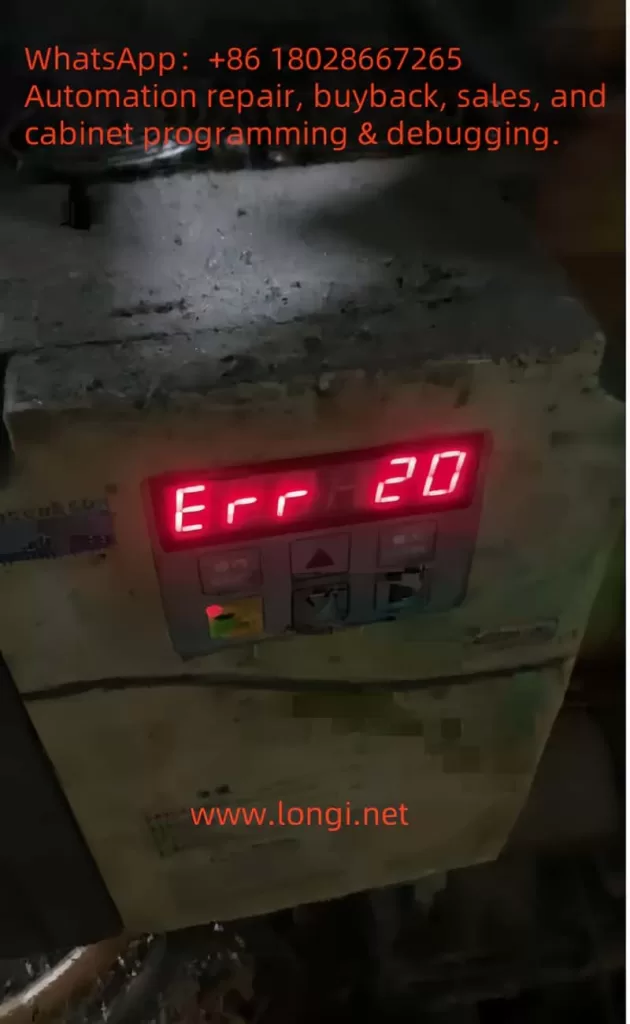
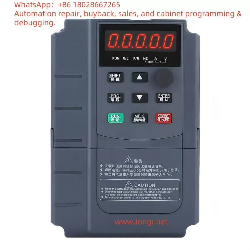
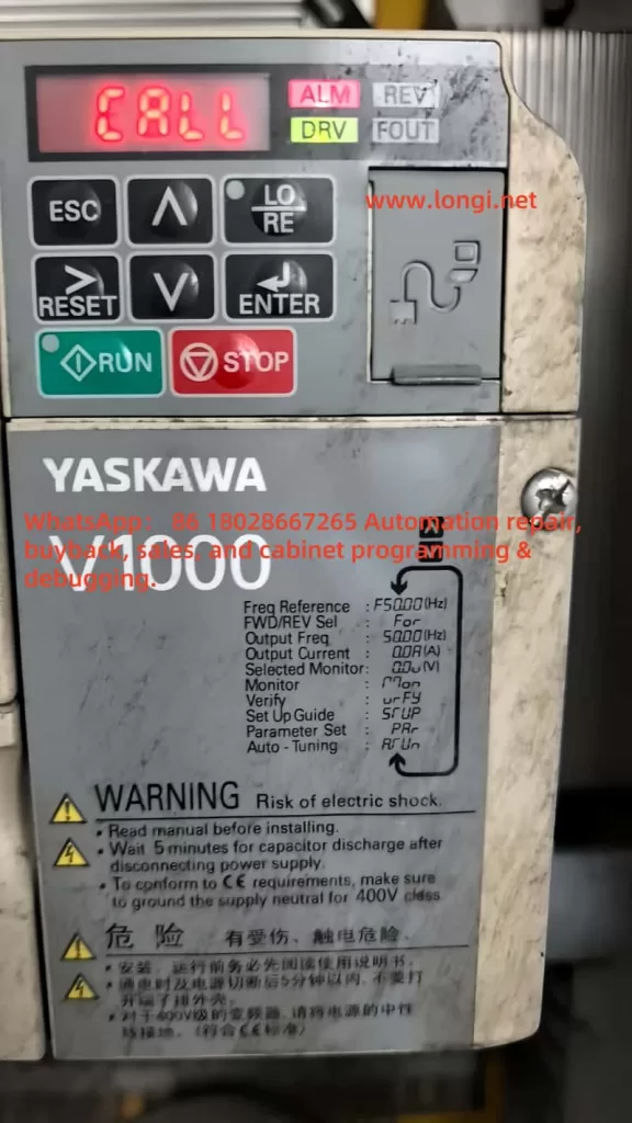
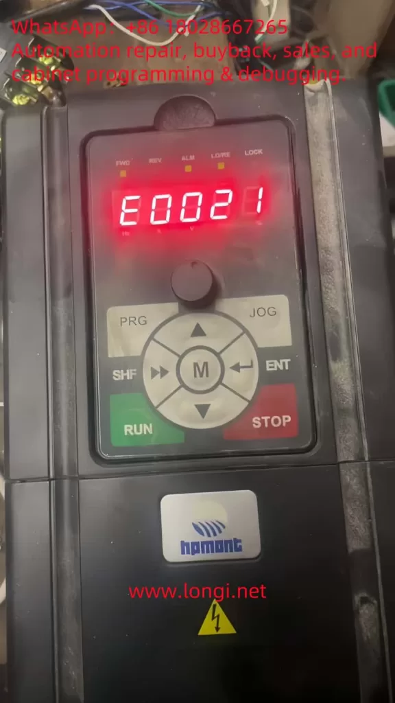
When the inverter displays the E0021 fault, as shown on the control panel with the illuminated “ALM” (alarm) light and the error code in red, it signifies a failure to read from or write to the EEPROM. This disruption can prevent the inverter from loading its operational parameters, resulting in startup failures, erratic behavior, or complete shutdowns. The user manual and fault description (e.g., “控制板EEPROM读写故障” or “Control Board EEPROM Read/Write Fault”) highlight this as a critical issue requiring immediate attention.

The Nature and Essence of the E0021 Fault

At its core, the E0021 fault reflects a breakdown in the inverter’s ability to manage its stored data. The EEPROM’s role is to ensure that the inverter retains its settings across power cycles, making it a cornerstone of reliable operation. A read/write error could stem from:

  • Data Access Failure: The control board cannot retrieve stored parameters.
  • Data Modification Failure: New settings or updates cannot be saved.
  • Data Integrity Issues: Corrupted data renders the EEPROM unreadable or unusable.

This fault’s essence lies in its potential to compromise the inverter’s functionality entirely. Without access to its configuration, the HD20 series inverter cannot control the connected motor effectively, impacting production lines and industrial processes.

Potential Causes of the E0021 Fault

Understanding the root causes of the E0021 fault is crucial for effective troubleshooting. Based on the fault description and general VFD principles, the following factors may contribute:

  1. Power Supply Instability
    Voltage fluctuations, surges, or sudden power losses can interrupt EEPROM operations. The HD20 series manual (Page 16) specifies a rated voltage (e.g., “额定电压”), and deviations from this range can affect data integrity.
  2. EEPROM Hardware Failure
    The EEPROM chip may degrade over time due to its finite write cycles (typically 100,000–1,000,000) or suffer damage from electrical stress, heat, or manufacturing defects.
  3. Data Corruption
    Electrical noise, improper shutdowns, or electromagnetic interference (EMI) in industrial environments can corrupt the EEPROM’s data, making it inaccessible.
  4. Firmware Issues
    Bugs or corruption in the inverter’s firmware, which manages EEPROM interactions, can lead to read/write errors. An incomplete firmware update could exacerbate this.
  5. Environmental Factors
    The manual (Page 20, “第三条 机械安装”) advises on installation conditions. Excessive heat, humidity, or dust can degrade the EEPROM and control board.
  6. Control Board Malfunction
    Damage to other components, such as solder joints or circuits interfacing with the EEPROM, can disrupt communication.
HD20

Diagnosing the E0021 Fault

Accurate diagnosis is the first step to resolution. Follow these steps to identify the cause:

  1. Observe Symptoms
    • Check the control panel (as per the screenshot) for the E0021 code and “ALM” light.
    • Note if the inverter fails to start, loses settings, or shows additional faults.
  2. Verify Power Supply
    • Measure input voltage with a multimeter to ensure it aligns with the manual’s specifications (e.g., 380V ±15%).
    • Look for fluctuations or noise using an oscilloscope if available.
  3. Inspect the Environment
    • Ensure compliance with installation guidelines (Page 20), checking for proper ventilation, temperature (e.g., 0°C–40°C), and EMI sources.
  4. Power Cycle the Inverter
    • Turn off the inverter, wait 5 minutes, and restart it to rule out temporary glitches.
  5. Check Firmware and Fault Logs
    • Access the fault history via the control panel (“PRG” and “ENT” buttons) to identify patterns.
    • Verify the firmware version against Hpmont’s latest release.
  6. Examine the Control Board
    • Power down safely and inspect for visible damage (e.g., burnt components, loose connections) around the EEPROM chip (often labeled “24Cxx” or “25Cxx”).

Resolving the E0021 Fault

Once diagnosed, apply these solutions tailored to the cause:

  1. Stabilize Power Supply
    • Install a surge protector or UPS to mitigate voltage issues.
    • Ensure proper grounding to reduce EMI.
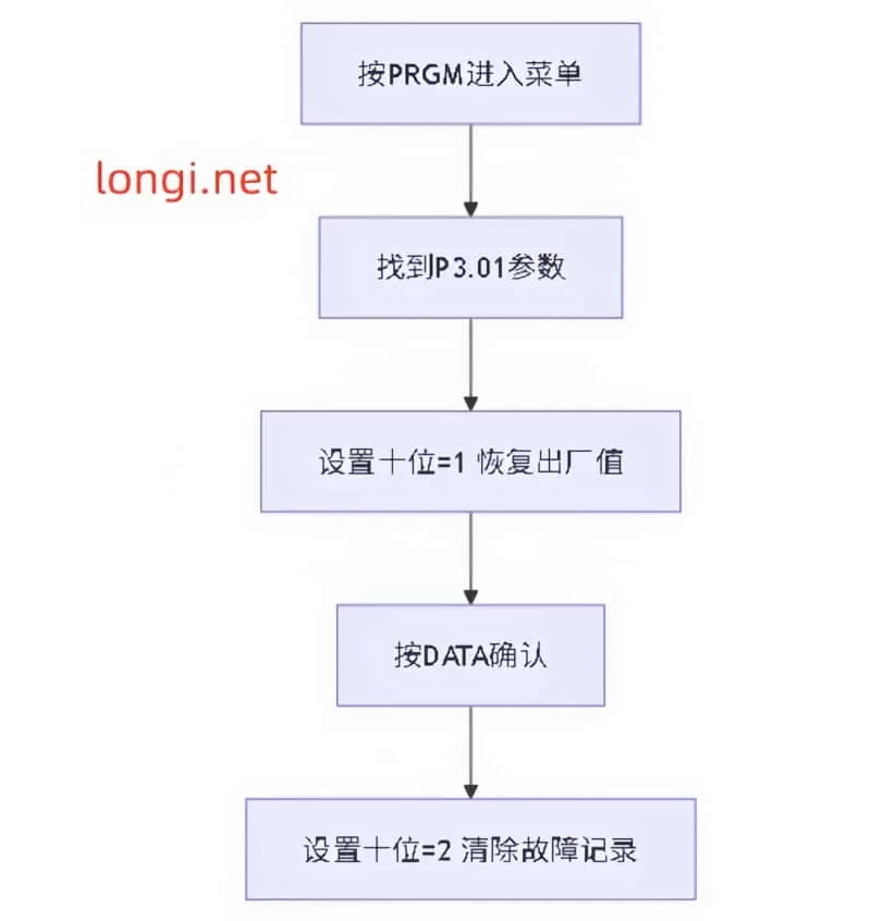
  2. Reset to Factory Settings
    • Use the control panel to reset parameters (refer to the manual for exact steps, typically via “PRG” and a reset code).
    • Reprogram settings post-reset, using backups if available.
  3. Update Firmware
    • Download the latest firmware from Hpmont’s website and follow update instructions, ensuring an uninterrupted process.
  4. Replace the EEPROM or Control Board
    • If the EEPROM is faulty, a technician can desolder and replace it with an identical chip, reprogramming it with default or backed-up data.
    • For broader control board issues, replace the entire board (e.g., compatible with HD20-4T5PSG), then reset and reconfigure.
  5. Address Environmental Issues
    • Enhance cooling, reduce humidity, or shield the inverter from interference sources.

Preventive Measures

To avoid future E0021 faults:

  • Maintain Power Quality: Use stabilizers and avoid frequent power interruptions.
  • Limit EEPROM Writes: Minimize unnecessary parameter changes.
  • Optimize Environment: Adhere to manual guidelines for temperature and humidity.
  • Regular Maintenance: Inspect and clean the inverter periodically.
  • Backup Parameters: Save settings regularly if the HD20 supports it.

Conclusion

The E0021 fault—Control Board EEPROM Read/Write Error—in the Hpmont HD20 series inverter is a significant challenge that can disrupt industrial operations. By understanding its nature as a data access failure, identifying causes like power instability or hardware issues, and applying systematic diagnosis and resolution steps, users can restore functionality efficiently. Preventive measures further ensure long-term reliability. For persistent issues, Hpmont’s technical support can provide expert assistance, leveraging the manual’s guidance and replacement parts. This comprehensive approach minimizes downtime and sustains the HD20 series’ performance in demanding applications.

Posted on

Understanding and Resolving the Err20 Fault (Module Overcurrent) in Baojie Servo AG Series

Understanding and Resolving the Err20 Fault (Module Overcurrent) in Baojie Servo AG Series

The Baojie Servo AG Series is a widely utilized industrial servo drive system known for its robust performance and advanced control features. However, like any sophisticated machinery, it is susceptible to operational faults, one of which is the “Err20” fault code displayed on the control panel. This error, accompanied by the indication of “module overcurrent,” signals a critical issue that requires immediate attention to prevent damage to the equipment and ensure uninterrupted production. This article delves into the nature of the Err20 fault, its potential causes, diagnostic procedures, and effective resolution strategies, drawing from the technical insights provided in the AG Series user manual.

ERR20

What is the Err20 Fault?

The Err20 fault code on the Baojie Servo AG Series control panel indicates a module overcurrent condition. Overcurrent occurs when the electrical current flowing through the servo drive’s power module exceeds its rated capacity. This can lead to overheating, potential damage to the internal components, or even a complete system shutdown to protect the hardware. The user manual highlights that such faults are part of the system’s safety diagnostics, designed to alert operators to issues that could compromise the drive’s integrity or the machinery it controls.

The display of “Err20” alongside a numerical value (e.g., 20) suggests a specific error category within the fault diagnostic framework outlined in Chapter 8 of the manual, “Fault Diagnosis Explanation.” This chapter emphasizes the importance of understanding alarm codes to identify and rectify underlying issues promptly.

Potential Causes of the Err20 Fault

Several factors can trigger the Err20 fault in the Baojie Servo AG Series. Understanding these causes is the first step toward effective troubleshooting:

  1. Overload Conditions: Excessive mechanical load on the servo motor, beyond its specified capacity, can cause the current to spike, triggering the overcurrent protection. This might occur due to jammed machinery or an improperly calibrated load.
  2. Short Circuits: An unintended electrical connection between the drive’s output terminals (e.g., U, V, W) or within the motor wiring can result in a short circuit, leading to a sudden surge in current.
  3. Faulty Wiring or Connections: Loose, damaged, or incorrectly installed wiring can disrupt normal current flow, potentially causing overcurrent conditions. The manual’s Chapter 3, “Installation and Debugging,” stresses the importance of secure and correct wiring practices.
  4. Component Wear or Failure: Over time, components such as the power module, capacitors, or transistors may degrade, especially if maintenance schedules (detailed in Chapter 9, “Maintenance and Care”) are not followed. A failing component can lead to irregular current draw.
  5. Improper Parameter Settings: Incorrect settings in the drive’s internal parameters, such as those adjustable via the operation panel (Chapter 5, “Parameter Setting Explanation”), can misconfigure the current limits, inadvertently allowing overcurrent situations.
  6. Environmental Factors: Operating the drive in harsh conditions—high temperatures, dust, or humidity—can affect its performance. The manual recommends regular cleaning (e.g., Section 9.4 for 7.5-11kW drive cleaning methods) to mitigate such risks.
PORCHESON AG10

Diagnostic Procedures

To resolve the Err20 fault, a systematic diagnostic approach is essential. The following steps, informed by the manual’s guidelines, should be undertaken:

  1. Initial Safety Check: Ensure the power supply is disconnected, as advised in Section 9.2 for insulation testing, to avoid electrical hazards during inspection.
  2. Visual Inspection: Examine the control panel, wiring, and motor for visible signs of damage, loose connections, or burn marks. Refer to Chapter 3.7 for the control terminal function table to verify wiring integrity.
  3. Review Operating Conditions: Check the mechanical load and operating environment. Compare the current load against the motor’s specifications listed in Chapter 4.7, “Servo Motor Parameter Table.”
  4. Parameter Verification: Access the operation panel (Section 5.1) to review and reset parameters under the “PA” or “PB” menus, ensuring they align with the application’s requirements.
  5. Testing with Diagnostic Tools: Use a multimeter to test for short circuits or abnormal current draw, following the insulation test procedures in Section 9.2. A resistance value of 5 MΩ or higher indicates normal insulation.
  6. Monitor System Logs: If the drive supports logging (as hinted in Chapter 6, “Computer Screen Parameter Monitoring”), review historical data to identify patterns leading to the fault.

Resolution Strategies

Once the cause is identified, the following corrective actions can be implemented:

  • Addressing Overload: Reduce the mechanical load by inspecting and repairing any jams or obstructions. Recalibrate the system to match the load to the motor’s rated capacity, as per the selection guidelines in Chapter 4.9.
  • Fixing Short Circuits: Trace and repair any shorted wires or terminals. Replace damaged cables or connectors, ensuring compliance with the wiring instructions in Chapter 3.11.
  • Repairing Connections: Tighten loose connections and replace any frayed or corroded wires. Refer to the user manual’s wiring diagrams for accuracy.
  • Replacing Faulty Components: If a component failure is suspected, replace it with a compatible part. The manual’s Section 9.3 provides a replacement schedule (e.g., fans every 3 years, capacitors every 5 years), which should guide the decision.
  • Adjusting Parameters: Correct any misconfigured parameters using the panel’s menu system. Ensure changes are made with the power off, as warned in Section 5.5.
  • Environmental Control: Clean the drive using the methods in Section 9.4 (e.g., blowing dust with air) and relocate it if environmental conditions are unfavorable. Install cooling systems if necessary.

Preventive Measures

To prevent recurrence of the Err20 fault, adopt the following practices:

  • Regular Maintenance: Follow the daily checks and periodic maintenance outlined in Chapter 9.1, including insulation tests and component replacements.
  • Training Operators: Ensure personnel are trained in the parameter settings and fault diagnosis procedures detailed in Chapters 5 and 8.
  • Environmental Monitoring: Maintain the operating environment within the recommended temperature and humidity ranges, as noted throughout the manual.
  • Load Management: Regularly assess and adjust the mechanical load to prevent exceeding the drive’s capacity.

Conclusion

The Err20 fault (module overcurrent) in the Baojie Servo AG Series is a critical alert that demands a thorough understanding of its causes and a structured approach to resolution. By leveraging the detailed guidance in the user manual—spanning installation, parameter settings, fault diagnosis, and maintenance—operators can effectively diagnose and rectify this issue. Implementing preventive measures ensures the longevity and reliability of the servo drive system, minimizing downtime and maintaining productivity. For complex cases or persistent faults, consulting the manufacturer’s technical support, as recommended in the manual’s preface, can provide additional expertise. With proactive management, the AG Series can continue to deliver optimal performance in industrial applications.

Posted on

Understanding and Resolving AL.72.8 Fault in Sanyo Denki SanMotion RS2 Series Servo Drivers

Introduction

Sanyo Denki’s SanMotion RS2 series servo drivers are renowned for their precision and reliability in industrial automation applications, such as robotics, CNC machines, and automated manufacturing systems. These drivers are designed to deliver high-performance motion control, but like any sophisticated electronic system, they can encounter faults that disrupt operations. One such fault is the AL.72.8 error code, which, based on available information, likely indicates a ±12V power supply abnormality. This fault can halt critical operations, making it essential for technicians and engineers to understand its causes, troubleshooting steps, and preventive measures. This article provides a comprehensive guide to diagnosing and resolving the AL.72.8 fault, ensuring minimal downtime and sustained system performance.

Understanding the AL.72.8 Fault Code

The AL.72.8 fault code, sometimes displayed as “72H” in hexadecimal format, is believed to indicate an abnormality in the ±12V power supply within the Sanyo Denki SanMotion RS2 series servo driver. The ±12V supply is a critical component that powers various control circuits, including:

  • Encoder Interfaces: For precise motor position feedback.
  • Communication Ports: Such as RS-485 or CANopen, used for interfacing with control systems.
  • Logic Circuits: For processing control signals and ensuring proper operation.

When the ±12V supply deviates from its nominal range (typically ±12V ±10%) or fails entirely, it can lead to erratic behavior, loss of control, or complete system shutdown. The fault is displayed prominently on the driver’s digital panel, as observed in user-provided images, signaling the need for immediate troubleshooting.

Potential Causes of AL.72.8

Several factors can trigger the AL.72.8 fault. Understanding these causes is the first step toward effective resolution:

  1. Internal Power Supply Failure:
    • The servo driver relies on an internal DC-DC converter to generate the ±12V supply from the main AC input (typically 200-240V AC). Failures in this converter, due to component wear, overheating, or manufacturing defects, can result in unstable or absent ±12V output.
    • Symptoms may include intermittent faults, random resets, or loss of communication with the motor or controller.
  2. Short Circuit or Open Circuit:
    • A short circuit in the ±12V line can cause excessive current draw, triggering protective circuits or damaging components.
    • An open circuit, conversely, prevents voltage from reaching critical components, leading to operational failures.
  3. Damaged Components:
    • Components on the control board, such as operational amplifiers, logic ICs, or microcontrollers powered by the ±12V supply, may fail due to overvoltage, overheating, or prolonged use.
    • Visual signs include burnt, discolored, or swollen components, particularly electrolytic capacitors.
  4. Incorrect Wiring:
    • While the ±12V supply is typically internal, external modifications or incorrect wiring during maintenance can introduce faults.
    • Unauthorized changes or loose connections can disrupt the power supply chain.
  5. Main Power Supply Issues:
    • The main AC input voltage must remain within 200-240V AC (±10%) for proper operation. Fluctuations, spikes, or sags can stress the internal DC-DC converter, affecting the ±12V supply.
    • Phase imbalances or power quality issues can exacerbate this problem.
  6. Aging Components:
    • Electrolytic capacitors, commonly used in power supply circuits, degrade over time, losing capacitance or increasing equivalent series resistance (ESR). This can destabilize the ±12V supply, especially under load.
    • Other components, such as voltage regulators, may also deteriorate with prolonged use.

The following table summarizes the potential causes and their impacts:

CausePotential Impact
Internal Power Supply FailureUnstable or missing ±12V supply, system shutdown
Short Circuit/Open CircuitExcessive current or no voltage to circuits
Damaged ComponentsAbnormal voltage behavior, circuit failure
Incorrect WiringDisrupted power supply, erratic operation
Main Power Supply IssuesStress on internal converter, voltage instability
Aging ComponentsReduced performance, intermittent faults

Troubleshooting the AL.72.8 Fault

Resolving the AL.72.8 fault requires a systematic approach to identify and address the root cause. Below are detailed troubleshooting steps:

  1. Verify Main Power Supply:
    • Use a true RMS multimeter to measure the input AC voltage at the driver’s power terminals, ensuring it is within 200-240V AC (±10%).
    • Check for voltage stability using a power quality analyzer if fluctuations are suspected.
    • Ensure the power source is free from phase imbalances or excessive noise.
  2. Inspect Internal and External Wiring:
    • With the power off and proper safety precautions (e.g., wearing ESD-safe gear), open the servo driver.
    • Visually inspect internal wiring for loose connections, burnt wires, or signs of overheating.
    • Check external connections, such as those to the motor or controller, for damage or improper wiring.
  3. Measure ±12V Supply:
    • Locate the ±12V test points on the control board, as specified in the RS2 series service manual.
    • With the driver powered on (in a safe, servo-off state), measure the voltage using a multimeter. The reading should be close to ±12V with minimal ripple (<1% of nominal voltage).
    • If the voltage is out of range, trace the ±12V lines to identify the point of failure.
  4. Check for Short Circuits:
    • Disconnect the driver from power.
    • Use a multimeter in continuity mode to check for shorts between the ±12V lines and ground or other circuits.
    • Measure resistance across the ±12V lines; it should be high (open circuit) unless intentional loads are present.
  5. Inspect Components:
    • Examine the control board for visible damage, such as bulging capacitors, discolored resistors, or burnt ICs.
    • If possible, measure the resistance or capacitance of suspect components and compare with expected values.
  6. Use Diagnostic Tools:
    • Utilize Sanyo Denki’s SANMOTION R Setup Software to access fault logs and additional error codes.
    • Monitor parameters related to power supply status to gain further insight into the fault.
  7. Consult Manufacturer’s Documentation:
    • Refer to the RS2 series manual for specific troubleshooting flowcharts or procedures for AL.72.8.
    • Check for service bulletins or known issues related to this fault code.
  8. Contact Technical Support:
    • If the issue persists, contact Sanyo Denki’s technical support or an authorized service center. Provide the model number, serial number, fault code, and detailed observations from your troubleshooting efforts.
    • Support contact details include:

    The following table outlines the troubleshooting steps and their objectives:

    StepObjective
    Verify Main Power SupplyEnsure input voltage is within specifications
    Inspect WiringIdentify loose or damaged connections
    Measure ±12V SupplyConfirm voltage stability and range
    Check for Short CircuitsDetect electrical faults in ±12V lines
    Inspect ComponentsIdentify damaged or faulty components
    Use Diagnostic ToolsAccess detailed fault logs and parameters
    Consult DocumentationFollow manufacturer’s troubleshooting guide
    Contact Technical SupportObtain expert assistance for unresolved issues

    Preventive Measures

    Preventing the AL.72.8 fault and similar issues requires proactive maintenance and careful system design. Here are key preventive measures:

    1. Regular Maintenance:
      • Schedule inspections every 6-12 months, depending on the operating environment.
      • Clean the driver to remove dust and debris, which can cause overheating or electrical issues.
      • Replace aging components, such as electrolytic capacitors, as per the manufacturer’s maintenance schedule.
    2. Stable Power Supply:
      • Install voltage stabilizers or uninterruptible power supply (UPS) systems to protect against power fluctuations.
      • Ensure the electrical panel includes overcurrent protection and surge suppression devices.
    3. Proper Installation:
      • Mount the servo driver vertically to optimize cooling and ensure adequate airflow.
      • Install in a clean, dry, and well-ventilated environment to prevent overheating and contamination.
    4. Monitor System Performance:
      • Use the driver’s built-in monitoring functions or diagnostic software to log temperatures, voltages, and other parameters.
      • Set up alerts for abnormal conditions, such as voltage deviations or temperature increases.
    5. Training and Documentation:
      • Train maintenance personnel on the specific RS2 series model and its fault codes.
      • Maintain up-to-date documentation, including service manuals and wiring diagrams, for quick reference.

    Conclusion

    The AL.72.8 fault code in Sanyo Denki SanMotion RS2 series servo drivers likely indicates a ±12V power supply abnormality, which can disrupt critical control functions. Potential causes include internal power supply failures, short circuits, damaged components, or main power supply issues. By following a systematic troubleshooting approach—verifying the main power supply, inspecting wiring, measuring voltages, and consulting technical support—technicians can effectively diagnose and resolve the issue. Preventive measures, such as regular maintenance, stable power supply, and proper installation, are essential for minimizing the occurrence of this fault and ensuring the longevity of the servo system. For further assistance, refer to the official Sanyo Denki documentation or contact their technical support team.

    Posted on

    Maintenance Analysis Report on YT‑3300 Smart Positioner Showing “TEST / FULL OUT 7535” Status

    I. Overview and Equipment Background

    This report addresses the status display of the Rotork YTC YT-3300 RDn 5201S smart valve positioner. The front panel shows the following:

    TEST  
    FULL OUT  
    7535
    

    The YT-3300 series smart positioner is produced by YTC (Young Tech Co., Ltd.), often labeled under the Rotork brand. It is designed for precise valve actuator control using a 4–20 mA input signal. The unit supports automatic calibration, self-diagnostics, manual testing, and performance optimization.


    TEST FULL OUT

    II. Interpretation of Display Information

    1. TEST Mode

    The “TEST” message indicates the unit is currently in self-test or calibration mode. This occurs typically during initial power-up, after parameter reset, or when manually triggered.

    2. FULL OUT

    “FULL OUT” means the actuator has moved to the end of its travel range—either fully open or fully closed—depending on the configured logic.

    3. 7535

    The number “7535” is not an error code. It usually represents the raw feedback signal from the internal position sensor, such as a potentiometer or encoder, scaled between 0–9999. This value gives the current travel position.


    III. Possible Root Causes

    The following table summarizes possible causes for this status:

    No.Possible CauseDescription
    1Power-on self-testAfter powering up or parameter loss, the device automatically initiates self-calibration.
    2Manual test triggeredThe test mode may have been manually entered via front-panel buttons.
    3Feedback sensor issueA stuck or damaged position sensor can cause the value (7535) to freeze or become invalid.
    4Air pressure problemInsufficient or unstable air pressure may prevent the actuator from completing movement.
    5Mainboard faultMalfunction of internal controller or microprocessor may lock the unit in test mode.

    YT-3300 RDn 5201S

    IV. Recommended Inspection and Repair Steps

    1. Safety and Initial Checks

    • Disconnect the actuator from live control and ensure safe access.
    • Ensure that air pressure is fully vented to prevent unintended valve motion.
    • Confirm the unit is grounded properly (ground resistance <100 ohms).

    2. Check Air Supply

    • Verify pressure gauges show clean, dry air within 0.14–0.7 MPa (1.4–7 bar).
    • Check for blocked air tubing or clogged filters.

    3. Exit TEST Mode

    • Press the ESC button repeatedly to try returning to the RUN display.
    • If that fails, power cycle the unit and enter Auto Calibration mode via the front panel.

    4. Execute Auto Calibration

    • Set the A/M switch to AUTO.
    • Use the keypad to navigate to “AUTO CAL” or “AUTO2 CAL” and execute.
    • The actuator will automatically stroke to both ends and calibrate zero and full travel points.
    • After successful calibration, the display should return to RUN mode.

    5. Verify Position Feedback

    If the value “7535” remains static or fails to reflect position changes:

    • Open the lower cover and check wiring to the potentiometer (typically yellow, white, blue wires).
    • Measure the feedback voltage (should range from ~0.5 to 4.5V DC).
    • If no variation is detected with actuator movement, the potentiometer or sensor board may need replacement.

    6. Diagnostics and Alarm Monitoring

    • Enter the DIAGNOSTIC menu to check for alarm codes or travel deviation alerts.
    • If high or low limit alarms (e.g., HH ALRM or LL ALRM) are detected, reset as per standard procedures.

    7. Functional Test and Tuning

    • After restoring to RUN mode, input varying mA signals and observe feedback value (PV) changes accordingly.
    • If actuator motion is slow or unstable, adjust Dead-Zone, Gain, or Filter settings to fine-tune performance.
    • Conduct partial stroke tests (PST) if available to verify control reliability.

    TEST FULL OUT

    V. Evaluation and Conclusion

    Depending on the inspection and action taken, the following scenarios are possible:

    • If Auto Calibration completes successfully and feedback changes smoothly: No hardware failure is present. The unit was simply in test mode after reset.
    • If TEST mode persists and feedback value remains frozen: The position feedback sensor or its circuit is likely faulty and needs replacement.
    • If actuator fails to move despite calibration attempts: Check for blocked pneumatic valves, damaged tubing, or insufficient pressure.
    • If diagnostic menu shows active alarms: Follow alarm-specific reset instructions.

    VI. Summary and Recommendations

    1. Preliminary Conclusion: The current “TEST / FULL OUT 7535” status likely indicates a post-reset auto-test, not a malfunction. However, persistent status or failed calibration points to feedback or hardware problems.
    2. Recommended Actions:
      • First attempt to complete auto calibration;
      • Check wiring, feedback sensor, and air supply;
      • Monitor diagnostic menu for error indicators;
      • Replace faulty components if auto-calibration cannot be completed.
    3. Follow-up Advice:
      • Acquire the official user manual for this specific model;
      • Record all air pressures, input/output values, alarms, and parameter settings during troubleshooting for future analysis;
      • If manual steps do not resolve the issue, contact the manufacturer or authorized support for further diagnostics or part replacement.

    Posted on

    Anchuan G9300 Series Frequency Inverter User Manual: Usage Guide

    Abstract

    The Anchuan G9300 series frequency inverter is a high-performance vector inverter widely used in various industrial automation applications. This article will provide a detailed introduction to the operation panel functions, parameter settings, password management, external terminal control, and fault codes and their solutions for the G9300 series frequency inverter, helping users better understand and utilize this equipment.


    G9300

    1. Operation Panel Function Introduction

    The operation panel of the Anchuan G9300 series frequency inverter is designed to be simple and functional, mainly consisting of the following parts:

    • Display Screen: Used to display current operating status, parameter settings, and other information.
    • Function Keys: Include PRG (Programming Key), ENTER (Confirm Key), SHIFT (Shift Key), RUN (Start Key), STOP/RST (Stop/Reset Key), and MF.K (Multi-Function Key).
    • Increment and Decrement Keys: Used to adjust parameter values or browse menus.

    1.1 Restoring Factory Settings

    Before using the G9300 series frequency inverter, it is usually necessary to restore the parameters to factory settings to ensure the device is in a known state. Here are the steps to restore factory settings:

    1. Enter Parameter Setting Mode: Press the PRG key to enter the first-level menu, then press the ENTER key to enter the second-level menu.
    2. Select Parameter Initialization Function: In the second-level menu, find the PP-01 (Parameter Initialization) function code.
    3. Restore Factory Parameters: Set PP-01 to 1, then press the ENTER key to confirm. At this point, all parameters of the frequency inverter will be restored to factory settings.

    1.2 Setting and Removing Passwords

    To protect parameter settings from being arbitrarily changed, the G9300 series frequency inverter provides a password protection function. Here are the steps to set and remove passwords:

    1. Setting a Password:
      • Enter the parameter setting mode and find the P7-11 (User Password) function code.
      • Set P7-11 to the desired password value (range 0~32766), then press the ENTER key to confirm.
    2. Removing a Password:
      • Enter the parameter setting mode and find the P7-11 function code.
      • Set P7-11 to 0, then press the ENTER key to confirm, and the password will be removed.

    1.3 Parameter Access Restrictions

    To further protect parameter settings, the G9300 series frequency inverter also provides a parameter locking function. Here are the steps to set parameter access restrictions:

    1. Locking Parameters:
      • Enter the parameter setting mode and find the PP-04 (Parameter Lock) function code.
      • Set PP-04 to 1, then press the ENTER key to confirm. At this point, all parameters will be locked and cannot be changed.
    2. Unlocking Parameters:
      • Enter the parameter setting mode and find the PP-04 function code.
      • Set PP-04 to 0, then press the ENTER key to confirm, and the parameter lock will be removed.

    2. External Terminal Forward/Reverse Control and External Potentiometer Speed Regulation

    The G9300 series frequency inverter supports forward/reverse control and potentiometer speed regulation through external terminals, making it very flexible and convenient in industrial automation control.

    2.1 External Terminal Forward/Reverse Control

    To achieve external terminal forward/reverse control, the following wiring and parameter settings are required:

    1. Wiring:
      • Connect the forward control signal to the DI1 terminal.
      • Connect the reverse control signal to the DI2 terminal.
      • Ensure the ground terminal (GND) is correctly connected.
    2. Parameter Settings:
      • Enter the parameter setting mode and find the P4-00 (DI1 Terminal Function Selection) and P4-01 (DI2 Terminal Function Selection) function codes.
      • Set P4-00 to 1 (Forward Operation), and P4-01 to 2 (Reverse Operation), then press the ENTER key to confirm.

    2.2 External Potentiometer Speed Regulation

    To achieve external potentiometer speed regulation, the following wiring and parameter settings are required:

    1. Wiring:
      • Connect the output of the potentiometer to the AI1 terminal.
      • Ensure the ground terminal (GND) is correctly connected.
    2. Parameter Settings:
      • Enter the parameter setting mode and find the P0-03 (Main Frequency Source A Selection) function code.
      • Set P0-03 to 4 (Keypad Potentiometer), then press the ENTER key to confirm.

    3. Fault Codes and Their Solutions

    During the use of the G9300 series frequency inverter, various faults may be encountered. Here are some common fault codes and their solutions:

    Fault CodeFault DescriptionSolution
    E001IGBT Short Circuit FaultCheck the IGBT module and its drive circuit, replace the IGBT module if necessary.
    E002Acceleration OvercurrentCheck if the acceleration time setting is too short or if the load is too large, adjust the acceleration time or reduce the load.
    E003Deceleration OvercurrentCheck if the deceleration time setting is too short or if the load is too large, adjust the deceleration time or reduce the load.
    E004Constant Speed OvercurrentCheck if the load is too large or if the motor parameters are set correctly, reduce the load or reset the motor parameters.
    E005Acceleration OvervoltageCheck if the acceleration time setting is too short or if the bus voltage is too high, adjust the acceleration time or check the bus voltage.
    E006Deceleration OvervoltageCheck if the deceleration time setting is too short or if the bus voltage is too high, adjust the deceleration time or check the bus voltage.
    E007Constant Speed OvervoltageCheck if the bus voltage is too high or if the load is too small, adjust the bus voltage or increase the load.
    E008Stop OvervoltageCheck if the stop mode setting is correct or if the bus voltage is too high, adjust the stop mode or check the bus voltage.
    E009UndervoltageCheck if the input voltage is normal or if the power line is in good contact, ensure the input voltage is stable.
    E010Inverter OverloadCheck if the load is too large or if the heat dissipation is good, reduce the load or improve the heat dissipation conditions.
    E011Motor OverloadCheck if the motor load is too large or if the heat dissipation is good, reduce the load or improve the heat dissipation conditions.
    E012Input Phase LossCheck if the input power supply is missing a phase, ensure all three phases are normally powered.
    E013Output Phase Loss or Three-Phase Output ImbalanceCheck if the output line is normal, ensure the three-phase output is balanced.
    E014Module OverheatCheck if the heat sink is blocked or if the ambient temperature is too high, ensure good heat dissipation.
    E015External FaultCheck if the external control line is normal, ensure the external control signal is correct.
    E016Communication AbnormalityCheck if the communication line is normal or if the communication parameters are set correctly, ensure stable communication.
    E017Motor Tuning AbnormalityCheck if the motor parameters are set correctly, re-perform motor tuning.
    E018Parameter Read/Write AbnormalityCheck if the parameter settings are correct, reset the parameters.
    E019Inverter Hardware AbnormalityCheck if the inverter hardware is normal, contact after-sales service if necessary.
    E020Motor Ground Short CircuitCheck if the motor line is short-circuited, ensure the motor insulation is good.
    E021AD Zero Drift Too LargeCheck if the analog input circuit is normal, contact after-sales service if necessary.
    E022Inverter Hardware Abnormality (Clear Latch Timeout)Check if the inverter hardware is normal, contact after-sales service if necessary.
    E023Motor Ground Short CircuitCheck if the motor line is short-circuited, ensure the motor insulation is good.
    E024AD Zero Drift Too LargeCheck if the analog input circuit is normal, contact after-sales service if necessary.
    E025User-Defined Fault 1Check if the setting of user-defined fault 1 is correct, ensure the logic is correct.
    E026User-Defined Fault 2Check if the setting of user-defined fault 2 is correct, ensure the logic is correct.
    E027Power-On Time ReachedCheck if the power-on time setting is correct, adjust the power-on time appropriately.
    E028PID Feedback Disconnection FaultCheck if the PID feedback line is normal, ensure the feedback signal is stable.
    E029PID Feedback Overlimit (Overvoltage) FaultCheck if the PID feedback signal is too large, adjust the PID parameters appropriately.
    E030Keypad STOP Key Stop FaultCheck if the STOP key is normal, ensure the control logic is correct.
    E031Hardware Current Limit TimeoutCheck if the current limit setting is correct or if the load is too large, adjust the current limit parameters or reduce the load.
    E032Auto-Reset Count ExceededCheck if the auto-reset count setting is correct, adjust the reset count appropriately.

    Standard Wiring Diagram for G9300

    4. Conclusion

    The Anchuan G9300 series frequency inverter is a powerful and high-performance industrial automation device. Through this article, users can better understand and use this equipment, including operation panel functions, parameter settings, password management, external terminal control, and fault codes and their solutions. In practical applications, users should perform parameter settings and fault troubleshooting according to specific needs to ensure the stable operation and high efficiency of the equipment.

    It is hoped that this article can help users better master the usage methods of the Anchuan G9300 series frequency inverter and improve the efficiency and quality of industrial automation control.

    Posted on

    K-DRIVE KD600M Series Variable Frequency Drive User Manual Guide

    Introduction

    The K-DRIVE KD600M series variable frequency drive (VFD) is a powerful and versatile device designed for motor speed and torque control in various industrial applications. This guide, based on the K-DRIVE KD600M series user manual, provides a detailed overview of the operation panel functions, parameter initialization, password and parameter access restrictions, external terminal forward/reverse control and potentiometer speed adjustment, as well as common fault codes and their resolutions. By mastering these features, users can operate and maintain the VFD efficiently and safely, ensuring optimal performance across different scenarios.

    KD600M-4T-2.2G

    Operation Panel Functions

    The KD600M series VFD’s operation panel is the central interface for user interaction, integrating intuitive buttons, LED indicators, and a 5-digit display for parameter settings, status monitoring, and motor control. Below are the key functionalities:

    Buttons and Controls

    The panel includes the following buttons:

    • PRG: Enters programming mode to access parameter menus.
    • ESC: Exits the current menu or cancels an operation.
    • OK: Confirms parameter settings or selections.
    • RUN: Starts motor operation.
    • STOP: Stops motor operation or resets faults.
    • QUICK: Quickly sets commonly used parameters.
    • JOG: Enters jog mode for testing or fine-tuning.
    • UP/DOWN: Adjusts parameter values or navigates menus.

    For example, to adjust the frequency from 0.00Hz to 5.00Hz, users can press PRG to enter the parameter menu, use the UP/DOWN keys to select the target parameter (e.g., P1-04), input the new value, and press OK to confirm.

    LED Indicators

    The panel’s LED indicators provide real-time status feedback:

    • RUN: Green, on indicates running, off indicates stopped, flashing indicates sleep mode.
    • L/D/C: Red, off indicates panel control, on indicates terminal control, flashing indicates communication control.
    • FWD/REV: Red, off indicates forward, on indicates reverse, flashing indicates direction mismatch.
    • TUNE/TC: Red, on indicates torque control, flashing indicates tuning or a fault.

    Display Screen

    The 5-digit LED display shows frequency, current, voltage, fault codes, and other information. Hexadecimal values are prefixed with “H.” (e.g., P7-29 displays as “H.3f”). The display supports multi-level menu navigation (group → code → value), enabling quick access and modification of parameters.

    Related Parameters

    Key parameters related to operation panel functions include:

    • P7-00 (Jog Run Frequency): Range: 0.00Hz to maximum frequency; Factory default: 6.00Hz.
    • P7-01 (Jog Acceleration Time): Range: 0.0s to 3000.0s; Factory default: 10.0s.
    • P7-02 (Jog Deceleration Time): Range: 0.0s to 3000.0s; Factory default: 10.0s.
    • P7-28 (QUICK/JOG Key Function Selection): Options: 0 (forward jog), 1 (forward/reverse switch), 2 (reverse jog), 3 (panel/remote switch), 4 (panel frequency source switch); Factory default: 0.
    • P7-16 (Keyboard Knob Precision): Options: 0 (0.01Hz) to 10 (10Hz); Factory default: 2.

    These features make the operation panel a powerful and flexible tool for various control needs.

    Parameter Initialization

    Parameter initialization is a critical step for restoring default settings or backing up user configurations. The KD600M series offers the following function codes:

    P0-28 (Parameter Initialization)

    • Options:
      • 0: No operation
      • 1: Restore factory settings (excludes motor parameters, records, and P0-20)
      • 2: Clear records
      • 3: Back up user parameters
      • 4: Restore backed-up parameters
    • Factory Default: 0
    • Modifiable State: Running state (★)

    To perform initialization, users should enter P0-28 while the device is stopped, set it to 1, and confirm. The VFD will revert to factory settings, preserving motor parameters and run records.

    P0-29 (Parameter Upload/Download)

    • Options:
      • 0: No function
      • 1: Upload parameters
      • 2: Download parameters (excludes P4 and A1)
      • 3: Download parameters (includes P4 and A1)
      • 4: Download all parameters
      • 5-7: Download modified parameters
    • Factory Default: 0
    • Modifiable State: Stopped or running state (☆)

    This function allows users to back up custom parameters or restore from a backup, suitable for multi-device configurations or fault recovery.

    Password and Parameter Access Restrictions

    To prevent unauthorized modifications, the KD600M series provides password protection and parameter access restrictions:

    Password Protection

    • P7-49 (User Password):
      • Range: 0 to 65535
      • Factory Default: 0
    • PF.00 (Factory Password):
      • Range: 0 to 65535
      • Factory Default: ***** (hidden for security)

    Users can enable password protection by setting P7-49. Fault codes like Err25 (EEPROM read/write failure) or Err1A (password entry limit exceeded) may indicate password-related issues, requiring EEPROM chip inspection or technical support.

    Parameter Access Restrictions

    • B0-00 (Function Code Read-Only Selection):
      • 0: Invalid (no restriction)
      • 1: Read-only (parameters cannot be modified)
      • Factory Default: 0
    • Parameter Status:
      • : Not modifiable during operation (e.g., P0-03: motor control).
      • : Manufacturer-only modification.
      • : Read-only (e.g., PF group parameters).

    These restrictions ensure the security of critical parameters, preventing accidental changes or unauthorized access.

    External Terminal Forward/Reverse Control and Potentiometer Speed Adjustment

    The KD600M series supports external terminal control for forward/reverse operation and potentiometer speed adjustment, ideal for automated systems.

    Forward/Reverse Control

    • Digital Input Terminals (DI1-DI10):
      • DI1: Default forward (function code 1).
      • DI2: Default reverse (function code 2).
      • Supports PNP/NPN modes, switchable via DIP switches.
      • Up to 10 digital inputs with optional IO1/IO2 expansion cards.
    • P5-11 (Terminal Command Mode):
      • 0: Two-wire mode 1
      • 1: Two-wire mode 2
      • 2: Three-wire mode 1
      • 3: Three-wire mode 2
      • Factory Default: 0

    Wiring Method:

    • Connect DI1 and DI2 to a PLC or switch, with the COM terminal as the common return.
    • Ensure secure connections to avoid short circuits or poor contact.

    Potentiometer Speed Adjustment

    • Analog Input Terminals (AI1, AI2):
      • Supports 0-10V or 4-20mA input.
      • P5-15 (AI1 Minimum Input): Range: 0.00V to 10.00V; Corresponding setting: -100.0% to 100.0%.
      • P5-16 (AI1 Maximum Input): Range: 0.00V to 10.00V; Corresponding setting: -100.0% to 100.0%.
    • Wiring Method:
      • Use a 1-5kΩ potentiometer, connecting to AI1 and +10V-GND terminals (+10V provides up to 10mA power).
      • Recommended wiring length is less than 20 meters to minimize signal interference.

    Setup Steps:

    1. Set P5-11 to 0 (two-wire mode 1) to enable terminal control.
    2. Configure P5-15 and P5-16 to define the potentiometer input range.
    3. Rotate the potentiometer and observe frequency changes on the display to ensure proper speed adjustment.

    Common Fault Codes and Resolutions

    The KD600M series manual lists various fault codes with corresponding resolution methods. Below are common faults and their troubleshooting steps:

    Fault CodeFault NameResolution Method
    Err01Inverter Module ProtectionCheck U, V, W terminals for shorts or grounding, inspect overheating, wiring, fans, and vents; contact support if unresolved.
    Err04Acceleration OvercurrentCheck output circuit, motor parameters, acceleration time (P9-22), V/F gain, voltage, load, and VFD capacity; adjust parameters.
    Err05Deceleration OvercurrentCheck output circuit, motor parameters, deceleration time (P9-23), voltage, load, brake unit/resistor, and flux gain; adjust parameters.
    Err06Constant Speed OvercurrentCheck output circuit, motor parameters, voltage, load, and VFD capacity; adjust parameters.
    Err08Acceleration OvervoltageCheck voltage, external force, acceleration time, brake unit/resistor, and motor parameters; adjust settings.
    Err09Deceleration OvervoltageCheck voltage, external force, deceleration time, and brake unit/resistor; adjust settings.
    Err10Constant Speed OvervoltageCheck voltage, external force, and resistor installation; adjust parameters.
    Err12Undervoltage FaultCheck power stability, voltage range, bus voltage, rectifier, and drive/control board; reset or contact support.
    Err13Drive OverloadReduce load, check motor condition, consider upgrading VFD.
    Err14Motor OverloadAdjust P9-01 settings, check load and motor condition, upgrade VFD if needed.
    Err15Drive OverheatingLower ambient temperature, clean vents, check fans and thermistor, replace module if necessary.
    Err17Current Detection FaultCheck wiring, current devices, and main/control board; contact support.
    Err20Ground Short CircuitCheck motor and cables for shorts, replace if needed; contact support.
    Err23Input Phase LossCheck power supply, drive/lightning/main board; contact support.
    Err24Output Phase LossCheck motor wires, output balance, drive/module; resolve fault or contact support.
    Err25EEPROM Operation FailureCheck EEPROM chip, replace main board if necessary; contact support.
    Err27Communication FaultCheck host, communication settings, and P8 group parameters; adjust wiring/parameters.
    Err28External FaultCheck DI terminal input, reset fault.
    Err29Speed Deviation ExcessiveExtend acceleration/deceleration time, reset P9-31/P9-32.
    Err30/31User-Defined Fault 1/2Check DI terminal input, reset fault.
    Err32PID Feedback LossCheck feedback signal, reset PA-13.
    Err33Quick Current LimitReduce load, extend acceleration time, or upgrade VFD.
    Err34Load Drop FaultReset or adjust P9-28 to P9-30 conditions.
    Err35Input Power FaultAdjust voltage, extend power cycle.
    Err37Parameter Storage AnomalyCheck DSP-EEPROM communication, replace main board if needed.
    Err39Run Time ReachedCheck run time, reset if necessary.
    Err40Cumulative Run Time ReachedCheck cumulative run time, reset.
    Err42Motor Switching During RunEnsure correct motor switching procedure.
    Err46Master-Slave Communication InterruptCheck master-slave communication connections.

    General Fault Handling Steps

    1. Power Off Check: Disconnect the VFD power before addressing any fault to ensure safety.
    2. Refer to Manual: Consult the manual’s troubleshooting section for specific steps based on the fault code.
    3. Parameter Adjustment: Adjust relevant parameters (e.g., acceleration time P9-22, deceleration time P9-23) according to the fault cause.
    4. Reset: Use the STOP key or set P9-11 (auto-reset attempts, 0-20, default 0) and P9-13 (reset interval, 0.1s-100.0s, default 1.0s) to reset faults.
    5. Technical Support: Contact K-DRIVE technical support if the fault persists.
    K-DRIVE KD600M

    Conclusion

    The K-DRIVE KD600M series VFD offers robust control capabilities through its intuitive operation panel, flexible parameter settings, and powerful external control features. By mastering the operation panel functions, parameter initialization, password protection, external terminal control, and fault resolution methods, users can ensure stable operation across various industrial scenarios. It is recommended to always refer to the user manual for detailed guidance and safety precautions to maximize the device’s performance and longevity.

    Posted on

    Yaskawa V1000 Series “CALL” Fault Analysis and Resolution Methods

    Introduction

    The Yaskawa V1000 series inverter is renowned for its efficient vector control performance and wide range of applications, making it a vital component in industrial automation, including systems like fans, pumps, and conveyor belts. However, during operation, the inverter may encounter various faults, with the “CALL” fault being a common communication-related issue. When the inverter’s display shows “CALL” accompanied by the ALM (alarm) light turning on, it typically indicates a communication link abnormality, which may result in system shutdown. This article provides an in-depth analysis of the nature of the “CALL” fault, its causes, and resolution methods, along with preventive measures to help users quickly restore equipment operation and enhance system reliability.

    V1000 call

    Nature of the “CALL” Fault

    In the Yaskawa V1000 series inverter, “CALL” generally signifies a communication-related issue, potentially indicating that the inverter is awaiting a signal from a master device (e.g., PLC) or has detected an error in the communication link. In some instances, “CALL” may serve as a general prompt, urging users to investigate specific fault codes (e.g., “CE” for MEMOBUS/Modbus communication errors) further. The illumination of the ALM light suggests the inverter has detected an abnormal state, typically interrupting output and allowing the motor to enter a free-stop mode.

    Based on relevant documentation, while “CALL” is not explicitly listed in the V1000 series fault code table, it is closely related to communication problems, possibly linked to codes like “CE” (MEMOBUS/Modbus communication error) or “bUS” (option card communication error). In certain communication protocols (e.g., Modbus), “CALL” might indicate a more severe communication issue, potentially necessitating inverter replacement.

    Causes of the “CALL” Fault

    The occurrence of a “CALL” fault may be attributed to the following causes:

    1. Communication Cable Wiring Issues:
      • Loose, broken, or short-circuited communication cables can lead to data transmission failure.
      • Incorrect wiring (e.g., improper terminal connections) may prevent communication between the inverter and the master device.
    2. Communication Parameter Configuration Errors:
      • Mismatched communication parameters (e.g., HS-01 slave address, HS-02 communication speed, HS-03 parity) with the master device.
      • For example, if the inverter’s baud rate is set to 9600 bps while the PLC is set to 19200 bps, communication will not establish.
    3. Hardware Problems:
      • Failure or improper installation of communication option cards (e.g., Modbus, CC-Link, or PROFIBUS-DP cards).
      • Damaged or poorly contacted communication terminals.
    4. Electromagnetic Interference (EMI):
      • Common electromagnetic noise in industrial environments (e.g., from motors or transformers) may disrupt communication signals, causing data transmission errors.
    5. Master Station Program Errors:
      • Incorrect configuration in the master device (e.g., PLC) may prevent proper command transmission or response reception.
      • For instance, the PLC may not have the correct slave address or communication protocol set.
    6. Communication Timeout:
      • If the inverter does not receive a response from the master within a specified time (e.g., as set by parameter HS-09), it may trigger a “CALL” fault.

    Steps to Resolve the “CALL” Fault

    To effectively address a “CALL” fault, follow these troubleshooting and resolution steps:

    CIMR-VB4A0018FBA

    Step 1: Inspect Physical Connections and Wiring

    • Check Cables: Inspect communication cables for damage, breaks, or short circuits. Ensure the correct cable type (e.g., RS-485 or RS-422) is used.
    • Verify Connections: Confirm all terminals are securely connected with no looseness or poor contact.
    • Refer to Manual: Ensure terminal connections (e.g., R+, R-, S+, S-) are correct as per the Yaskawa V1000 technical manual.

    Step 2: Verify Communication Parameters

    • Use the inverter’s digital operator panel or programming software (e.g., DriveWorksEZ) to check the following parameters:
      • HS-01 (Slave Address): Set to a unique address between 1-247, matching the master device.
      • HS-02 (Communication Speed): Confirm baud rate (e.g., 9600, 19200 bps) matches the master.
      • HS-03 (Parity): Select the appropriate parity setting (none, odd, even).
      • HS-04 (Fault Action Selection): Define the action upon communication failure (e.g., decelerate to stop or free stop).
      • HS-09 (Timeout Time): Adjust timeout to suit system needs.
    • Save changes and retest communication.

    Step 3: Perform Self-Diagnostic Test

    • Per the technical manual, set parameter H1-06 to 67 to enter communication test mode.
    • Power off, connect test terminals, power on again, and check if the display shows “PASS” (normal) or “CE” (fault).
    • This test helps identify issues with the communication line or hardware.

    Step 4: Adjust Terminal Resistor Settings

    • For RS-485 networks, ensure terminal resistors are correctly set (typically “ON”).
    • Check terminal resistor configuration per the technical manual.

    Step 5: Reduce Electromagnetic Interference

    • Check for EMI sources (e.g., motors, transformers) in the vicinity.
    • Use shielded cables and ensure proper grounding.
    • Install EMI filters or surge suppressors as recommended.

    Step 6: Inspect Master Device

    • Verify the PLC or other master device’s communication settings and program are correct.
    • Ensure commands sent by the master match the inverter’s communication protocol and parameters.

    Step 7: Consult Technical Support

    • If issues persist, refer to the Yaskawa V1000 technical manual’s troubleshooting section.
    • Contact Yaskawa support with details including model number, software version, purchase date, and fault description.

    Note: In Modbus communication, if “CALL” persists, it may indicate a severe fault, potentially requiring inverter replacement as a last resort.

    Preventive Measures

    To reduce the likelihood of “CALL” faults, consider the following preventive actions:

    1. Regular Maintenance of Communication Lines:
      • Periodically inspect cables and terminals for damage or looseness.
      • Promptly replace aged or damaged cables.
    2. Record Communication Parameters:
      • Document all communication settings (e.g., slave address, baud rate) for quick verification and adjustment.
      • Update records after system changes or modifications.
    3. Use EMI Protection Measures:
      • Employ shielded cables and ensure proper grounding.
      • Install EMI filters or surge suppressors to reduce noise impact.
    4. Keep Firmware Updated:
      • Regularly check for firmware updates.
      • Update firmware to address known communication issues.
    5. Routine System Checks:
      • Conduct regular inspections of the inverter, master device, and communication network to identify potential issues early.
    6. Train Operating Personnel:
      • Train operators and maintenance staff on inverter operation, fault codes, and troubleshooting procedures.
      • Ensure personnel can correctly interpret “CALL” and other fault messages and take appropriate action.

    Fault Code Reference Table

    Below are common communication-related fault codes for the V1000 series inverters and their descriptions:

    Fault CodeDescriptionPossible CausesResolution Methods
    CEMEMOBUS/Modbus Communication ErrorNo response from master, parameter mismatch, wiring issuesCheck parameters, wiring, perform self-diagnostic test
    bUSOption Card Communication ErrorOption card failure, wiring issues, incorrect terminal resistorCheck option card, wiring, adjust terminal resistor
    CALLCommunication Wait or ErrorAwaiting communication signal, wiring/parameter issues, hardware failureCheck wiring, parameters, perform self-diagnostic, consider replacement

    Conclusion

    The “CALL” fault is a significant communication-related issue in Yaskawa V1000 series inverters, potentially leading to system downtime and affecting production efficiency. By inspecting wiring, verifying communication parameters, performing self-diagnostic tests, and reducing electromagnetic interference, most “CALL” faults can be resolved. Implementing preventive measures such as regular maintenance, parameter documentation, and the use of shielded cables can greatly reduce the incidence of such faults. For complex or persistent issues, consulting the Yaskawa V1000 technical manual or contacting Yaskawa technical support for professional assistance is recommended. Ensuring the reliability of the communication system is crucial for maintaining stable operation in industrial applications.

    Posted on

    Edwards EPX Series Vacuum Pump User Guide

    Introduction

    Edwards, a global leader in vacuum technology, offers the EPX series vacuum pumps, renowned for their innovative design and exceptional performance. The EPX series is a high-vacuum primary pump that integrates regenerative and Holweck stage mechanisms, enabling efficient pumping from atmospheric pressure to ultimate vacuums as low as 1 x 10^-4 mbar or 1 x 10^-5 mbar, depending on the model. This design eliminates the need for additional turbomolecular pumps in many applications, simplifying system setups.

    EDWARDS EPX180L

    Widely used in industries such as semiconductor manufacturing, vacuum coating, analytical instrumentation, pharmaceuticals, and optoelectronics, the EPX series excels in high-vacuum, high-cleanliness, and high-reliability applications. This guide provides a comprehensive overview of the EPX series’ performance features, applications, operational procedures, usage details, and troubleshooting methods to assist users in maximizing the pump’s potential.

    1. Performance Features

    The EPX series vacuum pumps are engineered for superior performance in high-vacuum environments. Below are the key technical specifications:

    ParameterEPX180LEEPX180NEEPX500LEEPX500NE
    Peak Pumping Speed (m³/h)175175500500
    Ultimate Vacuum (mbar)<1 x 10^-4<1 x 10^-4<1 x 10^-5<1 x 10^-5
    Max Exhaust Pressure (bar)0.20.200
    Nitrogen Consumption (slm)025025
    Cooling Water Consumption (l/h)120120120120
    Supply Voltage (V)200/208/400200/208/400200/208/400200/208/400
    Power at Ultimate (kW)1.41.61.41.6
    Maximum Power (kW)3.03.03.03.0
    Weight (kg)45474648
    Inlet/Outlet ConnectionISO63/NW25ISO63/NW25ISO160/NW25ISO160/NW25
    Noise (dB(A))<56<56<56<56
    Vibration (mm/s, rms)<1.3<1.3<1.3<1.3
    • Pumping Speed and Vacuum: The EPX180 delivers a pumping speed of 175 m³/h, while the EPX500 achieves 500 m³/h. All models reach <1 x 10^-4 mbar, with the EPX500 capable of 1 x 10^-5 mbar due to an additional helical rotor stage.
    • Cooling System: Water cooling ensures a low environmental heat load, ideal for cleanroom settings.
    • Cleanliness: The oil- and grease-free mechanism prevents contamination, suitable for high-purity processes.
    • Nitrogen Purge: N variants (EPX180NE and EPX500NE) include a nitrogen purge facility for handling vapors and low-level corrosive gases and particulates.
    • Compact Design: Weighing approximately 45-48 kg, the EPX is smaller than equivalent turbomolecular pump and primary pump combinations.
    • Low Noise and Vibration: Noise levels below 56 dB(A) and inlet flange vibration under 1.3 mm/s ensure suitability for quiet environments.
    • Power Efficiency: Supports 200/208/400 V three-phase power, with power consumption of 1.4-1.6 kW at ultimate vacuum and a maximum of 3.0 kW.

    These features position the EPX series as a high-performance solution for demanding vacuum applications.

    2. Applications

    The EPX series vacuum pumps are designed for a variety of high-demand applications, including:

    • High-Vacuum Processes: Ideal for applications requiring higher vacuum levels than typical primary pumps, such as semiconductor load locks, vacuum coating, and analytical instruments, where it can replace turbomolecular and primary pump combinations, reducing system complexity and cost.
    • Frequent Pressure Cycling: Suitable for processes that cycle frequently between atmospheric and low pressures, such as load locks and rapid-cycle coating systems.
    • High-Cleanliness Requirements: The oil-free design makes it perfect for pharmaceuticals, electronics, and optoelectronics, ensuring contamination-free systems.
    • Corrosive Gas Handling: The nitrogen purge facility in N variants enables handling of vapors and low-level corrosive gases, suitable for light-duty corrosive processes.

    The EPX series’ versatility and efficiency make it a preferred choice in semiconductor, scientific research, and industrial production settings.

    3. Operational Procedures

    Proper operation of the EPX series vacuum pump is critical to ensuring performance and safety. Below are the detailed steps for operation:

    3.1 Preparation and Installation

    • Installation Location: Install the pump in the vacuum system before connecting to the electrical supply to prevent accidental operation during setup, which could cause injury or equipment damage.
    • Inlet Protection: Do not remove the inlet screen or operate the pump with the inlet exposed. If hazardous substances are involved, isolate the pump from the atmosphere and process system.
    • Piping Connections: Connect the pump inlet to the process system using flexible connections to minimize vibration and stress. Use short pipes with an inner diameter no smaller than the pump inlet. Remove the inlet flange protective cap before installation and use an Edwards centering O-ring and claw clamps to seal the connection.

    3.2 Connections

    • Cooling Water: Connect the cooling water supply and return lines via customer-specified water connectors (refer to Figure 2, items 4 and 9). Ensure cooling water meets environmental conditions (humidity and temperature, refer to Table 5).
    • Power Supply: Connect the electrical supply through a suitable fuse/isolator, ensuring proper grounding via the protective earth stud (Figure 2, item 3) in compliance with local electrical codes.
    • Control Interface: Connect external control equipment via the Tool Interface Module (TIM) or End User Controller (EUC). The EPX L, N, and NE series use the EUC for local and network control, while the EPX E series supports manual operation via EUC or PDT.

    3.3 Starting the Pump

    • Use the run button on the EUC (Figure 7, item 1) to start the pump. The run LED (green) illuminates when the pump is operating normally.
    • For EPX N series pumps, supply nitrogen purge gas through a 1/4-inch compression fitting labeled “N2 Inlet” using 1/4-inch OD tubing, ensuring stable flow (refer to Table 10).

    3.4 Monitoring and Control

    • Status Monitoring: Monitor pump status via front panel LEDs (refer to Table 1 and Figure 4):
      • Power LED (Green): Indicates main power supply is active.
      • Run LED (Green): Steady when running, flashing in idle mode.
      • Warning LED (Amber, EPX N only): Indicates low nitrogen flow.
      • Alarm LED (Red): Indicates shutdown due to a fault.
    • Control Options: Use the EUC or PDT menus (Normal, Status, Control, Setup) to check status, adjust controls, and configure parameters. The EUC display provides two-line, 16-character pump status information.

    3.5 Stopping the Pump

    • Use the stop button on the EUC (Figure 7, item 10) to stop the pump.
    • In emergencies, connect to an emergency stop circuit to disconnect power immediately, requiring a separate start or reset action.

    Precautions

    • Ensure proper grounding to prevent electrical hazards.
    • Verify cooling water supply meets requirements to avoid overheating.
    • For EPX N series, regularly confirm the nitrogen purge system is functioning correctly.

    4. Usage Details

    The EPX series vacuum pumps offer detailed operational features covering their operating range, variant functionalities, and protective mechanisms:

    • Operating Range: The pumps operate from atmospheric pressure to ultimate vacuum without lubricating or sealing fluids in the pumping chamber, ensuring a clean system with no oil back-migration.
    • Variants and Applications:
      • EPX L: Designed for clean tasks (e.g., load locks), supports local and network control via EUC.
      • EPX N: Equipped with a gas module for nitrogen purging, suitable for light-duty applications with diluted process gases.
      • EPX NE: Light-duty application pump with network and local control.
      • EPX E: Supports manual operation via EUC or PDT, ideal for network-controlled setups.
    • Capacity and Configuration: Available in 180 m³/h (EPX180LE/NE) and 500 m³/h (EPX500LE/NE) capacities, with voltage options of 200/208 V or 400 V, and water connector options of 1/4, 3/8, or 9/16-inch BSP or no quick connects.
    • Cooling System: Integrated water cooling circuit suits cleanroom environments, avoiding the drawbacks of fan cooling.
    • Performance Optimization: The EPX Twin offers enhanced performance between 1 bar and 0.2 mbar, ideal for load locks and rapid cycling applications.
    • Protective Mechanisms: Equipped with sensors like thermal cut-off switches to detect overheating and trigger automatic shutdowns. The EPX N series includes a nitrogen purge flow switch (set to 12 slm) to monitor flow.
    EDWARDS EPX180NE

    5. Troubleshooting

    Below are common issues with the EPX series vacuum pumps and their solutions:

    IssuePossible CauseSolution
    Pump Shutdown (Alarm LED On)Overheating, drive faultCool the pump for at least 20 minutes, check cooling water supply (Section 2.4), restart.
    Low Nitrogen Flow (Warning LED On)Insufficient nitrogen supplyVerify nitrogen flow to the gas module; if persistent, contact Edwards service center.
    Noise on RestartRapid reapplication of run signalAllow the pump to fully stop before reapplying the run signal; noise is harmless.
    Connection IssuesIncorrect control equipment connectionsVerify interface connections (Section 3.11); if persistent, contact Edwards service center.

    Safety and Maintenance

    • Electrical Safety: Do not operate without proper grounding or correct electrical connections. The pump contains no user-serviceable parts; maintenance must be performed by Edwards professionals, with power disconnected for at least 4 minutes before removing covers.
    • Pump Seizure: If the pump seizes, wear gloves, eye protection, and a face mask due to potential aluminum sulfate dust and sulfurous odors.
    • Service Support: Contact Edwards service centers for repairs, spares, or accessories, providing model, serial number, and part details. Returns require a completed HS2 contamination form.

    6. Conclusion

    The Edwards EPX series vacuum pumps offer outstanding performance, versatility, and reliability for high-vacuum applications. Their oil-free design, high pumping speeds, and nitrogen purge capabilities make them ideal for semiconductor, pharmaceutical, and research industries. By following proper operational procedures, regular monitoring, and timely maintenance.

    Posted on

    Comprehensive User Guide for Jintech JTE280 Series Variable Frequency Drive (VFD)

    I. Control Panel Operations and Parameter Management

    1. Panel Interface Fundamentals

    The JTE280 features two panel configurations (Fig.4-1/4-2) with essential controls:

    • RUN: Start operation (requires P0.03=0)
    • REV/JOG: Reverse/Jog (configured via P3.52)
    • STOP/RESET: Halt/Reset faults
    • PRGM: Access parameters (5-sec hold locks keyboard)
    • ▲/▼: Adjust values (real-time speed adjustment)
    • <<: Toggle monitoring parameters (J-00~J-11)

    2. Factory Reset Procedure

    Execute through hierarchical menu:

    graph TD
        A[Press PRGM] --> B[Locate P3.01]
        B --> C[Set tens-digit=1 for default]
        C --> D[Confirm with DATA]
        D --> E[Set tens-digit=2 to clear faults]

    3. Security Configuration

    • Password Protection: Set P0.00 (0001-9999)
    • Access Levels (P3.01 units-digit):
    • 0: Full access
    • 1: Only P3.01 adjustable
    • 2: Only P0.02+P3.01 adjustable
    • Keyboard Lock: 5-sec PRGM hold

    II. External Control Implementation

    1. Terminal-Based Motor Control

    Critical Parameters:

    P0.03 = 1      ; Terminal control mode
    P4.08 = 0      ; 2-wire control scheme 1

    Wiring Specification:

    • Forward: FWD-DCM short
    • Reverse: REV-DCM short
    • Stop: Open circuit

    2. External Potentiometer Configuration

    Parameter Chain:

    P0.01 = 0      ; Potentiometer mode
    P1.01 = 1.00   ; VI gain default
    P1.02 = 0.00V  ; Min voltage
    P1.05 = 50.00Hz; Max frequency

    Connection Protocol:

    1. Potentiometer wiper → VI terminal
    2. Potentiometer V+ → +10V terminal
    3. Potentiometer V- → ACM terminal

    Recommended: 10kΩ linear potentiometer

    280-A

    III. Fault Diagnosis Matrix

    CodeDescriptionRoot CausesCorrective Actions
    E-01Acceleration OCLoad surge/short acc.timeIncrease P0.17, inspect mechanics
    E-02Deceleration OCRegenerative energyEnable P5.02 overvoltage stall
    E-11DC Bus UnderVInput <305VVerify supply, set P5.07=1
    E-12DC Bus OverVRapid decelerationAdjust braking parameters
    E-15IGBT OverheatCooling failureClean vents, reduce loading

    Troubleshooting Flow:

    1. Resolve hardware issues
    2. Press STOP/RESET to clear
    3. Analyze history (P6.00-P6.11)

    IV. Advanced Application Techniques

    1. Multi-Speed Programming

    P4.00=1  # M11=Speed-bit1
    P4.01=2  # M12=Speed-bit2
    # Speed1: M11 ON
    # Speed2: M12 ON
    # Speed3: M11+M12 ON

    2. Winding Control (Textile Applications)

    P9.00=1      ; Enable wobble
    P9.04=10.0%  ; Amplitude
    P9.06=5.0s   ; Cycle time

    3. PID Pressure Regulation

    P7.00=1      ; Enable PID
    P7.10=0.85   ; Proportional gain
    P7.16=25.00  ; Preset frequency
    JTE280

    Key Operational Notes:

    1. High-altitude (>1000m) requires derating (Fig.1-3)
    2. Long cables (>30m) mandate output reactors (Sec.1.3.8)
    3. Braking resistors must comply with Table 3-25 specifications

    This guide synthesizes critical operational knowledge from the 117-page manual. For complete technical specifications, refer to Chapter 9 (Application Examples) and Appendix (MODBUS protocols). Proper implementation of these procedures will optimize drive performance while ensuring operational safety.

    Posted on

    Delta MS300 Inverter CP30 Fault Analysis and Solutions

    Introduction

    Delta MS300 series inverters are widely used in industrial fields due to their high performance and reliability. However, various faults may occur during use. Among them, CP30 fault (internal communication abnormality) is a relatively common fault. This article will systematically analyze the causes, troubleshooting methods, and solutions of CP30 faults based on official materials and actual cases, helping engineers quickly locate problems and restore equipment operation.

    CP30

    I. Definition and Mechanism of CP30 Fault

    1.1 Official Definition

    According to Delta’s official technical documents, CP30 is a dedicated error code for internal communication of MS300 series inverters, indicating a communication interruption or signal delay between the control board and the drive board. This fault is usually related to abnormal hardware connections, power fluctuations, or component aging.

    1.2 Fault Trigger Scenarios

    • Intermittent Fault: The equipment suddenly reports an error after running for a period of time. It temporarily recovers after restarting, but the fault recurs repeatedly.
    • After Environmental Changes: Such as restarting after holidays or when there are significant changes in ambient temperature and humidity.
    • During Load Fluctuations: Load mutations or frequent starts and stops increase communication pressure.

    1.3 Fault Mechanism

    The core mechanism of the CP30 fault lies in abnormal data interaction between the control board and the drive board, which may be caused by the following reasons:

    1. Hardware Connection Issues:
      • Loose or oxidized wiring at the control terminal block.
      • Communication cables longer than 15 meters without signal repeaters.
      • Power lines and control lines not laid in separate layers, causing electromagnetic interference.
    2. Power Fluctuations:
      • The 5V/12V output voltage of the switching power supply fluctuates beyond ±5%, leading to unstable power supply for the control board.
      • Harmonic interference or voltage mutations in the input power.
    3. Component Aging:
      • RS485 communication chip failure on the main control board.
      • EEPROM memory damage or degradation of optocoupler devices (such as PC923, PC929).
    4. Software and Parameters:
      • Incompatible firmware versions or incorrect parameter configurations.
      • Communication protocol settings not matching the upper computer.
    MS300

    II. Troubleshooting Process for CP30 Fault

    2.1 Preliminary Inspection

    2.1.1 Appearance and Wiring Inspection

    1. Control Terminal Block:
      • Check if the wiring is loose or oxidized, focusing on communication terminals (such as RS485 interfaces).
      • Ensure that the shielding layer of the cable is grounded at one end to avoid grounding loop interference.
    2. Communication Cables:
      • Measure the cable length. If it exceeds 15 meters, install a signal repeater.
      • Check if the cable insulation layer is damaged to avoid short circuits or crosstalk.
    3. Layered Wiring:
      • Ensure that power lines (main circuits) and control lines (signal lines) are laid separately with a spacing of at least 30cm.

    2.1.2 Power and Grounding Inspection

    1. Switching Power Supply Test:
      • Use a multimeter to measure the control board power supply voltage (5V/12V). The fluctuation should be ≤±5%.
      • If the voltage is abnormal, check if the filter capacitor is aging or replace the switching power supply module.
    2. Grounding Verification:
      • Confirm that the grounding terminal is reliably connected and the grounding resistance is ≤4Ω.
      • Avoid sharing ground wires with power lines to prevent ground wire interference.

    2.2 In-depth Hardware Detection

    2.2.1 Circuit Board Inspection

    1. Connector Status:
      • Disassemble the inverter and observe if the connectors between the main control board and the drive board are offset, broken, or oxidized.
      • Clean the connectors and re-plug them to ensure good contact.
    2. Capacitor and Optocoupler Detection:
      • Measure the capacitance value of the main circuit filter capacitor. If it is below 80% of the rated value, replace it.
      • Use an oscilloscope to detect the input and output waveforms of optocoupler devices (such as PC923, PC929) to confirm there is no distortion or delay.

    2.2.2 Communication Chip Test

    1. RS485 Chip Detection:
      • Use a multimeter to measure the voltage difference between the A and B lines of the RS485 chip. The normal value should be 2-3V.
      • If the voltage is abnormal, replace the RS485 communication chip or the control board.
    2. EEPROM Verification:
      • Test the EEPROM by initializing the inverter parameters (retain motor nameplate data).
      • If the fault persists after initialization, replace the control board.

    2.3 Software and Parameter Inspection

    1. Parameter Initialization:
      • Restore the inverter to factory settings and re-enter motor parameters (such as power, number of poles, rated current, etc.).
      • Confirm that parameters 06-17~06-22 (communication-related parameters) are set correctly.
    2. Firmware Version Check:
      • Contact Delta or check the firmware version through the inverter panel.
      • If the version is too old, upgrade to the latest version to fix potential communication vulnerabilities.
    3. Communication Protocol Verification:
      • Confirm that the communication protocol (such as Modbus, CANopen) of the upper computer (such as PLC, touch screen) matches the inverter settings.
      • Use a serial debugging tool to simulate communication and verify if data interaction is normal.

    III. Solutions for CP30 Fault

    3.1 Hardware Repair

    1. Wiring Optimization:
      • Replace oxidized or loose wiring terminals and use tinned copper wires with crimped terminals.
      • Install signal repeaters or use shielded twisted pairs to improve communication stability.
    2. Component Replacement:
      • Replace aging capacitors, optocouplers, or RS485 chips.
      • If the control board is damaged, contact Delta for original replacement boards.
    3. Power Supply Improvement:
      • Install three-phase reactors or harmonic filters to suppress input power harmonics.
      • Replace with high-precision switching power supply modules to ensure stable power supply.

    3.2 Software Adjustment

    1. Parameter Optimization:
      • Adjust the communication timeout time (parameters 14-70~14-73) and extend it appropriately to adapt to complex environments.
      • Disable unnecessary communication functions to reduce data interaction.
    2. Firmware Upgrade:
      • Download the latest firmware from Delta’s official website and upgrade the control board with a dedicated programmer.
    3. Protocol Adaptation:
      • Modify the upper computer program to ensure that the communication instruction format is compatible with the inverter.
      • Use intermediate devices (such as gateways) to convert different communication protocols.

    3.3 Preventive Measures

    1. Regular Maintenance:
      • Check the tightness of wiring terminals quarterly and clean dust on circuit boards.
      • Test capacitor values and optocoupler performance annually, and replace aging components in advance.
    2. Environmental Optimization:
      • Ensure that the inverter is installed in a well-ventilated environment to avoid high temperature, high humidity, or dust pollution.
      • Keep away from high-power equipment or electromagnetic interference sources, and install shielding covers if necessary.
    3. Backup and Monitoring:
      • Regularly back up inverter parameters for quick recovery in case of faults.
      • Install communication status monitoring modules for real-time abnormality alerts.

    IV. Typical Case Analysis

    Case 1: Intermittent CP30 Fault

    Phenomenon: An MS300 inverter in a factory frequently reported CP30 after holidays. It temporarily operated normally after restarting but failed again after a few hours.
    Troubleshooting Process:

    1. Checked the control terminal block and found severe oxidation of the wiring, increasing contact resistance.
    2. Measured the communication cable length as 20 meters without a repeater, causing significant signal attenuation.
    3. Disassembled the inverter and found oxidation on the pins of the RS485 chip on the main control board, with distorted communication waveforms.
      Solution:
    4. Cleaned and tightened the wiring terminals and replaced oxidized cables.
    5. Installed a signal repeater to shorten the effective communication distance.
    6. Replaced the RS485 chip to restore communication stability.
      Result: The fault was completely eliminated, and the equipment operated normally for 3 months.

    Case 2: CP30 Fault Caused by Parameter Configuration

    Phenomenon: A newly installed MS300 inverter frequently reported CP30 during commissioning, but no hardware abnormalities were found.
    Troubleshooting Process:

    1. Found that the engineer mistakenly set the communication timeout time to an extremely short value, causing data interaction interruption.
    2. The firmware version was too old, with communication protocol compatibility issues.
      Solution:
    3. Adjusted the communication timeout time to the default value and optimized other communication parameters.
    4. Upgraded the firmware to the latest version to fix protocol vulnerabilities.
      Result: The fault was immediately eliminated, and the equipment was successfully put into operation.

    V. Conclusion

    The CP30 fault is a relatively complex internal communication abnormality in Delta MS300 inverters, requiring systematic troubleshooting from multiple dimensions such as hardware connections, power quality, component aging, and software configurations. By standardizing wiring, conducting regular maintenance, optimizing parameters, and replacing components, such faults can be effectively solved. Engineers should combine official materials with actual cases, flexibly use detection tools, and gradually narrow down the fault scope to achieve rapid repair.