1. Introduction
Variable Frequency Drives (VFDs) play an increasingly critical role in water supply, HVAC, and industrial automation. Beyond simple motor speed control, VFDs are now deeply integrated into supervisory systems, exchanging data with PLCs and HMIs to enable centralized control and monitoring.
However, in real-world operation, communication faults are not uncommon. In particular, when multiple drives are connected in a network, a single issue can sometimes cause a complete loss of communication across all devices, leading to system downtime.
This article examines a case involving three AS180 series VFDs manufactured by STEP Electric in a water supply system. The drives simultaneously reported Er.43 communication fault codes, and the HMI displayed “Communicating…”. By analyzing the fault mechanism and field conditions, we summarize the causes, provide structured troubleshooting steps, and present practical solutions.
2. Fault Description
2.1 System Overview
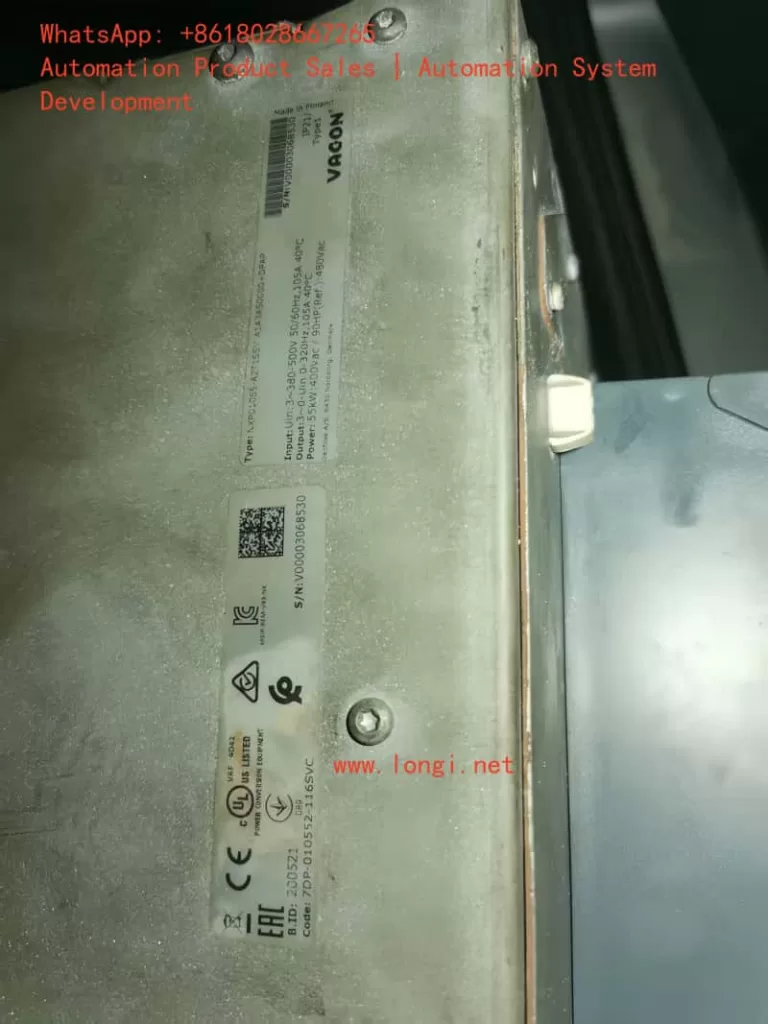
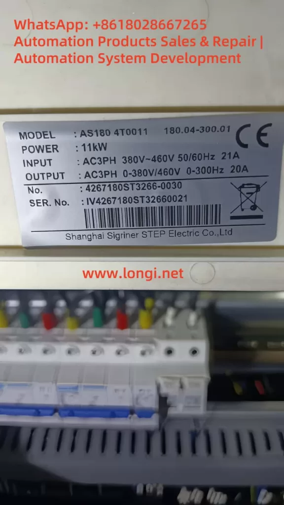
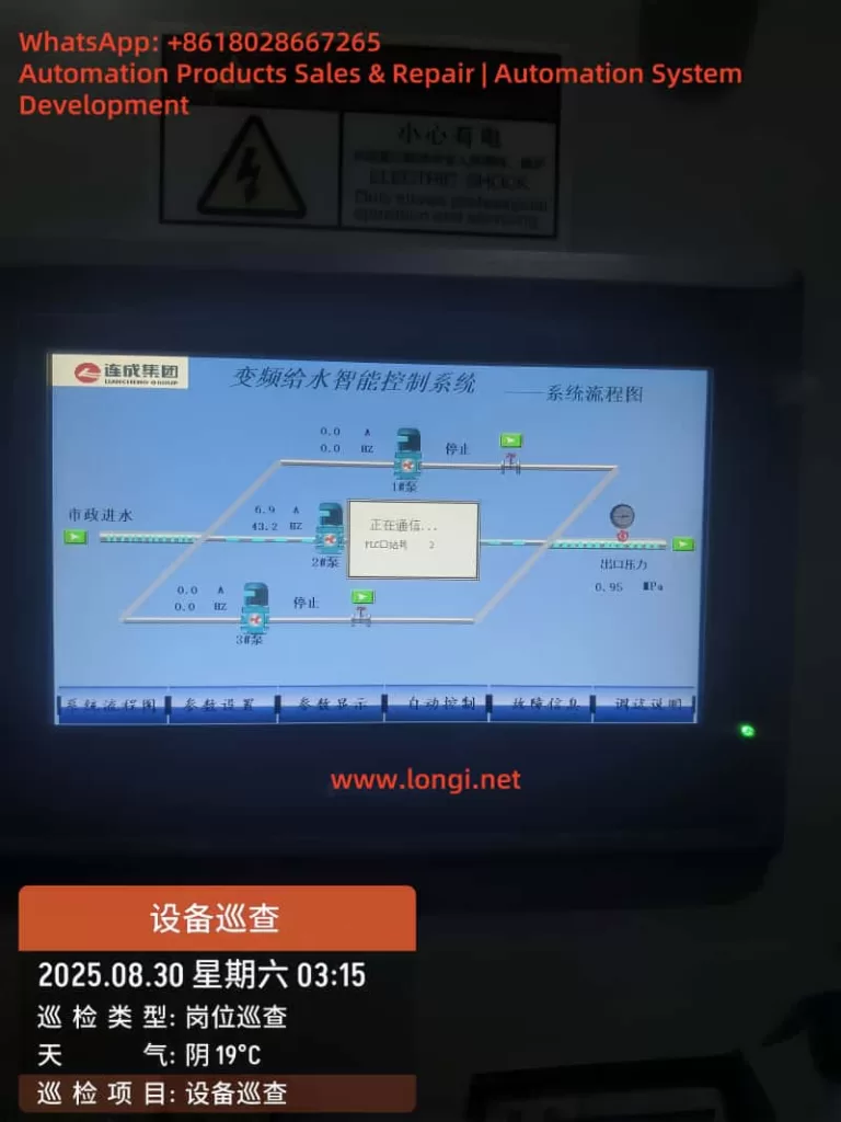
The system consists of three 11 kW AS180 VFDs, each driving a water pump. The VFDs are connected to a PLC and an HMI, forming an intelligent constant-pressure water supply system. Both the run command and frequency reference for the drives are configured to be received via the RS-485 communication interface, using the Modbus-RTU protocol.
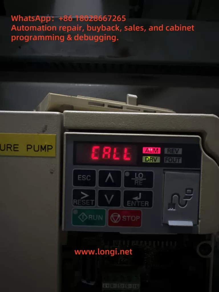
2.2 Fault Symptoms
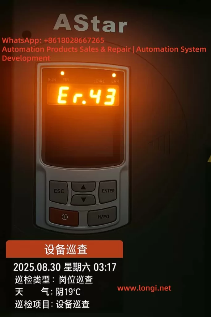
During operation, all three VFDs displayed “Er.43” on their front panels simultaneously. The HMI screen froze with the message “Communicating…”, while the PLC could no longer read current, frequency, or pressure data from the drives. This effectively disabled automatic control of the pumps.
2.3 Manual Interpretation
According to the AS180 manual, fault code 43 is defined as:
- Communication fault – No communication data received within the specified time window.
This indicates that the VFDs did not detect any polling signal from the master device (PLC/HMI) during the configured timeout period, thus triggering communication loss protection.
3. Root Cause Analysis
The simultaneous occurrence of Er.43 alarms across all three VFDs suggests that the problem was not isolated to an individual drive. Instead, the issue likely originated from the master device or the RS-485 bus. The potential causes can be categorized as follows:
3.1 Master Device Failure
If the PLC or HMI fails to transmit Modbus queries, the drives will all report a communication fault. Possible reasons include:
- PLC/HMI power supply failure or reset;
- Serial communication module failure or gateway malfunction (RS-232/485 converter);
- Software/program crash, leaving the serial port idle.
3.2 RS-485 Physical Layer Issues
The RS-485 bus is inherently sensitive to wiring quality and terminations. Typical physical-layer issues include:
- Open circuit or miswiring of A/B lines;
- Reversed polarity (A and B swapped);
- Multiple or missing termination resistors, causing reflections;
- Absence of bias resistors, leaving the bus floating;
- Poor shielding or proximity to high-voltage cables, leading to EMI.
3.3 Parameter Configuration Errors
If the drives and master are not configured with consistent communication parameters, the entire system may fail:
- Inconsistent baud rate, parity, or stop bits;
- Duplicate station addresses causing response conflicts;
- VFD command channel not set to “communication reference.”
3.4 Electromagnetic Interference
In pump rooms or industrial sites, large motors and contactors switch frequently, generating strong electromagnetic noise. If RS-485 wiring runs parallel to power cables without proper shielding, frame loss or CRC errors can occur, leading to timeouts and Er.43 alarms.
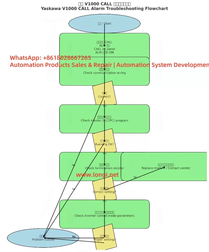
4. Structured Troubleshooting Steps
Based on experience, the following step-by-step troubleshooting process is recommended:
Step 1: Verify Master Device Status
- Check that PLC/HMI power supplies are stable;
- Observe communication LED indicators on the PLC serial port or gateway;
- If necessary, reboot the PLC/HMI and check whether VFD alarms clear;
- If the master does not transmit at all, the problem lies upstream.
Step 2: Inspect Wiring Integrity
- Use a multimeter to check continuity of A/B lines;
- Verify there is no short circuit to ground;
- Confirm polarity is correct (A to A, B to B);
- Ensure terminals are properly tightened.
Step 3: Check Communication Parameters
- Each VFD must have a unique station address (e.g., 1, 2, 3);
- Baud rate, parity, and stop bits must match the PLC settings;
- Run and frequency command channels must be set to “communication.”
Step 4: Adjust Timeout Settings
- Parameter P94.19 (communication timeout) can be temporarily increased from the default 2 seconds to 5–10 seconds to reduce nuisance trips during debugging;
- Parameter P94.18 (communication loss protection) should remain enabled for system safety.
Step 5: Mitigate Interference
- Use shielded twisted-pair cable for RS-485 wiring;
- Connect the shield to ground at one end only;
- Keep communication wiring at least 30 cm away from power cables;
- Route communication lines separately whenever possible.
Step 6: Isolate and Test Individually
- Disconnect two VFDs, leaving only one connected to the master;
- Verify stable communication with a single device;
- Reconnect drives one by one to determine if issues are related to wiring topology or specific devices.
5. Case Study Findings
During on-site troubleshooting of this specific case, the following observations were made:
- All three drives had consistent parameters, with station numbers 1, 2, and 3;
- RS-485 cabling was intact, but termination resistors were mistakenly installed on all three drives, rather than only at the two ends of the bus;
- The PLC serial module was intermittently freezing in the noisy environment, causing polling to stop;
- The HMI simply displayed “Communicating…” while awaiting PLC responses.
Corrective Actions Taken
- Removed redundant termination resistors, leaving only one at each end of the RS-485 bus (120 Ω each);
- Added bias resistors (1 kΩ pull-up/pull-down) to stabilize the bus idle state;
- Improved shielding and grounding of the communication line;
- Replaced the PLC serial port module and implemented a watchdog function in software.
Outcome
After implementing these measures, the three drives resumed stable communication. The Er.43 alarms disappeared, and the water supply system returned to normal automatic operation.
6. Lessons Learned and Best Practices
From this case, several important lessons can be drawn:
- Simultaneous alarms across all drives usually point to the master device or the RS-485 backbone, rather than the drives themselves.
- Follow RS-485 wiring standards strictly. Proper termination, biasing, and shielding are essential for stable communication.
- Tune communication protection parameters wisely. Extending the timeout can reduce nuisance trips during debugging, but should be optimized during commissioning.
- EMI is a real threat. In pump rooms and industrial settings, interference must be mitigated through careful routing and shielding.
- Equip maintenance teams with RS-485 analyzers. These tools can quickly identify whether polling frames are transmitted and whether responses are correct, greatly accelerating troubleshooting.
7. Conclusion
The AS180 VFD is widely applied in water supply and industrial systems, but communication reliability is crucial for its proper operation. The Er.43 communication fault is not typically caused by defects in the VFD itself, but by issues in the RS-485 bus or master station.
By applying a systematic troubleshooting approach—from verifying the master, inspecting wiring, checking parameters, to mitigating interference—engineers can quickly locate and resolve the root cause.
This case study demonstrates that once proper RS-485 wiring practices were restored and the PLC module replaced, the system regained full stability.
For operators and maintenance engineers, this provides both a reference case and a practical methodology to handle similar faults effectively in the future.