
I. Control Panel Operations and Parameter Management
1. Panel Interface Fundamentals
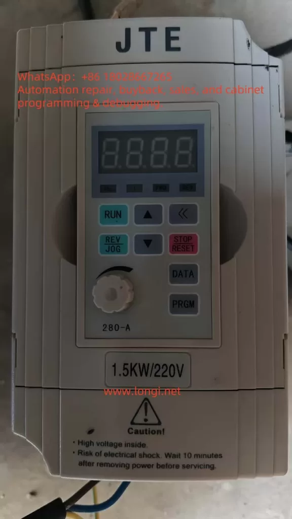
The JTE280 features two panel configurations (Fig.4-1/4-2) with essential controls:
RUN: Start operation (requires P0.03=0)REV/JOG: Reverse/Jog (configured via P3.52)STOP/RESET: Halt/Reset faultsPRGM: Access parameters (5-sec hold locks keyboard)▲/▼: Adjust values (real-time speed adjustment)<<: Toggle monitoring parameters (J-00~J-11)
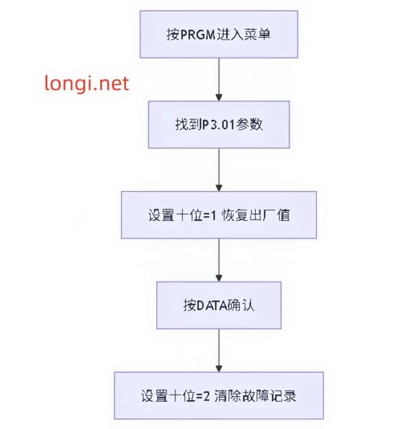
2. Factory Reset Procedure
Execute through hierarchical menu:
graph TD
    A[Press PRGM] --> B[Locate P3.01]
    B --> C[Set tens-digit=1 for default]
    C --> D[Confirm with DATA]
    D --> E[Set tens-digit=2 to clear faults]
3. Security Configuration
- Password Protection: Set P0.00 (0001-9999)
- Access Levels (P3.01 units-digit):
0: Full access1: Only P3.01 adjustable2: Only P0.02+P3.01 adjustable- Keyboard Lock: 5-sec
PRGMhold
II. External Control Implementation
1. Terminal-Based Motor Control
Critical Parameters:
P0.03 = 1      ; Terminal control mode
P4.08 = 0      ; 2-wire control scheme 1
Wiring Specification:
- Forward: FWD-DCM short
- Reverse: REV-DCM short
- Stop: Open circuit
2. External Potentiometer Configuration
Parameter Chain:
P0.01 = 0      ; Potentiometer mode
P1.01 = 1.00   ; VI gain default
P1.02 = 0.00V  ; Min voltage
P1.05 = 50.00Hz; Max frequency
Connection Protocol:
- Potentiometer wiper → VI terminal
- Potentiometer V+ → +10V terminal
- Potentiometer V- → ACM terminal
Recommended: 10kΩ linear potentiometer
III. Fault Diagnosis Matrix
| Code | Description | Root Causes | Corrective Actions |
|---|---|---|---|
| E-01 | Acceleration OC | Load surge/short acc.time | Increase P0.17, inspect mechanics |
| E-02 | Deceleration OC | Regenerative energy | Enable P5.02 overvoltage stall |
| E-11 | DC Bus UnderV | Input <305V | Verify supply, set P5.07=1 |
| E-12 | DC Bus OverV | Rapid deceleration | Adjust braking parameters |
| E-15 | IGBT Overheat | Cooling failure | Clean vents, reduce loading |
Troubleshooting Flow:
- Resolve hardware issues
- Press
STOP/RESETto clear - Analyze history (P6.00-P6.11)
IV. Advanced Application Techniques
1. Multi-Speed Programming
P4.00=1  # M11=Speed-bit1
P4.01=2  # M12=Speed-bit2
# Speed1: M11 ON
# Speed2: M12 ON
# Speed3: M11+M12 ON
2. Winding Control (Textile Applications)
P9.00=1      ; Enable wobble
P9.04=10.0%  ; Amplitude
P9.06=5.0s   ; Cycle time
3. PID Pressure Regulation
P7.00=1      ; Enable PID
P7.10=0.85   ; Proportional gain
P7.16=25.00  ; Preset frequency
Key Operational Notes:
- High-altitude (>1000m) requires derating (Fig.1-3)
- Long cables (>30m) mandate output reactors (Sec.1.3.8)
- Braking resistors must comply with Table 3-25 specifications
This guide synthesizes critical operational knowledge from the 117-page manual. For complete technical specifications, refer to Chapter 9 (Application Examples) and Appendix (MODBUS protocols). Proper implementation of these procedures will optimize drive performance while ensuring operational safety.