
The EST900 series inverter from Yiste, as a high-performance vector inverter, is widely applied in the control and speed regulation of three-phase asynchronous motors. This article, based on the official manual, will elaborate in detail on its operation panel functions, parameter setting methods, external terminal control and speed regulation implementation, as well as handling measures for common fault codes, helping users quickly master the usage skills.
I. Introduction to Operation Panel Functions and Parameter Settings
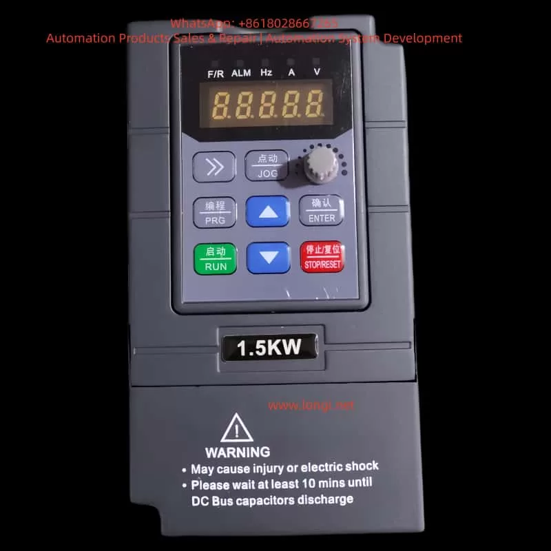
(A) Overview of Operation Panel Functions
The EST900 series inverter comes standard with an LED operation panel, which offers a variety of functions:
- Status Monitoring: It can display key information such as operating frequency, current, voltage, and fault codes in real time.
- Parameter Setting: It supports viewing and modifying functional parameters.
- Operation Control: Control commands such as start, stop, and forward/reverse rotation can be executed through the panel.
- Indicator Lights: It is equipped with indicator lights including RUN (operation), LOCAL/REMOT (control source), FWD/REV (direction), and TUNE/TC (tuning/torque/fault), which visually reflect the equipment status.
(B) Factory Parameter Settings
During debugging or when parameters are in disarray, a factory reset operation can be performed:
- Steps:
- Enter the FP – 01 parameter.
- Set it to 1 (restore factory parameters, excluding motor parameters).
- Press the ENTER key to confirm.
- Wait for the display to restore, indicating parameter initialization is complete.
- Notes:
- FP – 01 = 2 can clear fault records and other information.
- FP – 01 = 4 can back up the current parameters.
- FP – 01 = 501 can restore the backed-up parameters.
(C) Password Setting and Clearing
To prevent misoperation, a user password can be set:
- Setting a Password:
- Enter FP – 00 and set it to a non-zero value (e.g., 1234).
- After exiting, the password needs to be entered when accessing parameters again.
- Clearing a Password:
- Set FP – 00 to 0.
(D) Parameter Access Restrictions
Parameter access can be restricted in the following ways:
- Parameter Group Display Control:
- Set the FP – 02 parameter to control whether Group A and Group U parameters are displayed.
- For example, setting it to “11” can hide some parameter groups to prevent mismodification.
- Prohibition of Modification during Operation:
- Some parameters marked with “★” cannot be modified during operation and need to be set after shutdown.
II. External Terminal Forward/Reverse Rotation Control and Potentiometer Speed Regulation
(A) External Terminal Forward/Reverse Rotation Control
- Wiring Terminals:
- D11: Forward rotation (FWD)
- D12: Reverse rotation (REV)
- COM: Digital input common terminal
- Parameter Settings:
| Parameter Code | Name | Setting Value | Description |
| —- | —- | —- | —- |
| F0 – 02 | Operation Command Selection | 1 | Terminal control |
| F4 – 00 | D11 Function Selection | 1 | Forward rotation |
| F4 – 01 | D12 Function Selection | 2 | Reverse rotation |
| F4 – 11 | Terminal Command Mode | 0 | Two-wire type 1 | - Note: If a three-wire control system is used, set F4 – 11 = 2 or 3 and cooperate with other DI terminals.
(B) External Potentiometer Speed Regulation
- Wiring Terminals:
- +10V: Positive pole of potentiometer power supply
- GND: Negative pole of potentiometer power supply
- A11: Analog voltage input (0 – 10V)
- Parameter Settings:
| Parameter Code | Name | Setting Value | Description |
| —- | —- | —- | —- |
| F0 – 03 | Main Frequency Command Selection | 2 | A11 |
| F4 – 13~F4 – 16 | A11 Curve Settings | Adjust according to actual conditions | Minimum/maximum input corresponds to frequency | - Tip: It is recommended that the potentiometer resistance be between 1kΩ and 5kΩ to ensure that the current does not exceed 10mA.
III. Common Fault Codes and Handling Methods
The EST900 series inverter has a comprehensive fault diagnosis function. The following are common faults and their handling methods:
(A) Overcurrent Faults
| Fault Code | Name | Possible Causes | Handling Measures |
|---|---|---|---|
| Err02 | Acceleration Overcurrent | Motor short circuit, too short acceleration time | Check motor insulation, increase acceleration time |
| Err03 | Deceleration Overcurrent | Short deceleration time, large load inertia | Increase deceleration time, install a braking resistor |
| Err04 | Constant-speed Overcurrent | Load mutation, mismatched motor parameters | Check the load, perform motor tuning again |
(B) Overvoltage Faults
| Fault Code | Name | Possible Causes | Handling Measures |
|---|---|---|---|
| Err05 | Acceleration Overvoltage | High input voltage, external force during acceleration | Check power supply voltage, enable overvoltage suppression |
| Err06 | Deceleration Overvoltage | Short deceleration time, energy feedback | Increase deceleration time, install a braking unit |
| Err07 | Constant-speed Overvoltage | External force dragging during operation | Check the mechanical system, enable overvoltage suppression |
(C) Other Common Faults
| Fault Code | Name | Possible Causes | Handling Measures |
|---|---|---|---|
| Err09 | Undervoltage Fault | Low power supply voltage, rectifier bridge fault | Check the power supply, measure the bus voltage |
| Err10 | Inverter Overload | Excessive load, undersized selection | Check the load, replace with a higher-power inverter |
| Err11 | Motor Overload | Excessive motor load, improper protection parameter setting | Adjust the F9 – 01 motor overload gain |
| Err14 | Module Overheating | Poor heat dissipation, fan fault | Clean the air duct, replace the fan |
| Err16 | Communication Fault | Wiring error, improper parameter setting | Check the communication line, set FD group parameters |
(D) Fault Reset Methods
- Press the STOP/RESET key on the panel.
- Set a DI terminal to the “Fault Reset” function (F4 – xx = 9).
- Write “2000H = 7” through communication.
- Power off and restart (wait for more than 10 minutes).
IV. Conclusion
The Yiste EST900 series inverter is powerful and flexible in operation, capable of adapting to various industrial scenarios. Through the introduction in this article, users can master the following key contents:
- Basic usage methods of the operation panel and parameter setting skills.
- How to control and regulate the speed of the motor using external terminals and a potentiometer.
- Diagnostic ideas and handling skills for common faults.
- Effective use of password management and parameter protection mechanisms.
During actual use, it is recommended that users strictly follow the manual specifications for wiring and parameter setting, and regularly carry out maintenance work to ensure the long-term stable operation of the equipment.