
Introduction
The Delixi EM60 series inverter is a robust variable frequency drive (VFD) designed to regulate the speed and torque of AC motors in industrial applications. Engineered for reliability, it features advanced protective mechanisms to safeguard both the inverter and the connected motor. One such protection is the “quick current limit,” which prevents damage from sudden overcurrent conditions. However, when this limit is exceeded for too long, the inverter triggers the ERR34 fault code, known as “quick current limit timeout” (快速限流超时). This article explores the meaning of the ERR34 fault, its potential causes, and provides a detailed guide on how to troubleshoot and repair this issue, drawing on the Delixi EM60 series user manual and practical VFD maintenance principles.
What Does ERR34 Mean?
The ERR34 fault code indicates that the inverter’s output current has surpassed the quick current limit threshold for a duration exceeding the specified timeout period. In the Delixi EM60 series, this protective feature is part of the motor control strategy, managed through parameters in the P1 group (pages 31-73 of the user manual). The quick current limit activates during transient overcurrent events—such as sudden load spikes or short circuits—by reducing the output frequency or voltage to stabilize the current. If the current remains high beyond the timeout threshold (typically a few seconds), the inverter halts operation and displays ERR34 to prevent damage.
This fault serves as a critical alert, signaling that the system could not resolve an overcurrent condition within the allotted time. Understanding its implications is key to diagnosing whether the issue lies in the motor, wiring, parameters, or the inverter itself.
Potential Causes of ERR34
Several factors can trigger the ERR34 fault. Based on the manual’s fault diagnosis section (pages 191-199) and general VFD operation, the following are the most likely culprits:
- Motor Overload
Excessive mechanical load, such as a jammed rotor or heavy machinery, forces the motor to draw more current than the inverter can safely handle, activating the current limit. - Incorrect Parameter Settings
Misconfigured settings in the P1 group (motor control parameters, pages 31-73) or P3 group (programmable functions, pages 47-117), such as a low current limit or short timeout period, can cause the fault to trigger prematurely. - Power Supply Instability
Voltage fluctuations, harmonics, or transients in the input power can disrupt the inverter’s ability to regulate current, as emphasized in the safety guidelines (pages 6-7). - Wiring Issues
Loose connections, damaged cables, or short circuits between the inverter and motor can lead to abnormal current spikes. The manual’s installation section (page 213) highlights the importance of secure wiring. - Motor or Inverter Faults
Internal motor issues (e.g., shorted windings) or inverter hardware failures (e.g., damaged IGBT modules or current sensors) can sustain overcurrent conditions. - Environmental Factors
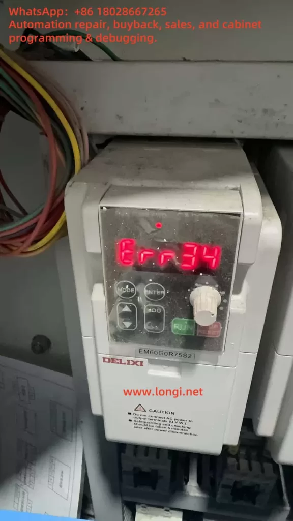
Dust accumulation or poor ventilation, as observed in the image of an EM60G0R7S2 inverter, can overheat the unit, exacerbating current-related problems.
Troubleshooting the ERR34 Fault
Diagnosing the ERR34 fault requires a systematic approach. The following steps, inspired by the manual’s troubleshooting sections (pages 56-128) and practical experience, will help identify the root cause:
- Ensure Safety
Disconnect the power supply and verify with a multimeter that the system is de-energized, adhering to the caution label warning against live servicing. - Check Motor Load
Inspect the motor and driven equipment for mechanical issues like binding or overloading. Measure the current draw with a clamp meter and compare it to the motor’s rated capacity. - Review Parameter Settings
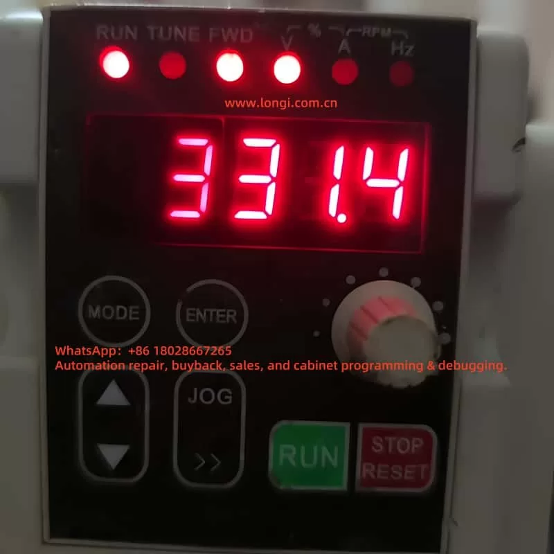
Use the inverter’s keypad (featuring “MODE,” “ENTER,” and arrow buttons) to access the P1 group. Verify the current limit (e.g., P1-03) and acceleration/deceleration times (P1-09, P1-10, page 159). Adjust if they are too restrictive for the application. - Inspect Wiring
Examine all connections between the inverter and motor for looseness, fraying, or burn marks. Test for continuity and insulation resistance to rule out shorts. - Assess Power Supply
Measure the input voltage to ensure it’s within the specified range (e.g., 380V ± 15% for three-phase models). Use a power quality analyzer to detect noise or surges. - Monitor Environmental Conditions
Check the inverter’s surroundings for dust or high temperatures (recommended range: 0-40°C). Clean the unit and ensure proper ventilation. - Reset and Test
After addressing potential issues, reset the fault via the “STOP” button or power cycle (page 128). Run the system at a low speed to observe if ERR34 reoccurs.
Solutions and Repairs
Once the cause is pinpointed, apply these solutions:
- Reduce Overload
Lighten the mechanical load or upgrade to a higher-capacity motor and inverter if the demand exceeds specifications. - Adjust Parameters
Increase the current limit or extend the timeout period in the P1 group to accommodate normal operation. For example, lengthening acceleration time (P1-09) can reduce startup current spikes. - Stabilize Power
Install a voltage stabilizer or harmonic filter to ensure consistent input power. - Repair Wiring
Tighten connections or replace faulty cables, ensuring compliance with the manual’s wiring guidelines (page 213). - Fix Hardware
- Motor: Test windings with an insulation tester; repair or replace if defective.
- Inverter: If internal components are suspected (e.g., IGBTs), consult Delixi support for repair, as detailed diagnostics may require proprietary tools (P8 group, page 66).
- Improve Environment
Relocate the inverter to a cleaner, cooler area or add cooling fans to mitigate thermal stress.
Preventive Measures
To avoid future ERR34 faults:
- Conduct regular maintenance on the motor and machinery to prevent overloads.
- Periodically review P1 and P3 group settings, adjusting for changes in load or application (pages 31-117).
- Install surge protectors to safeguard against power issues.
- Clean the inverter routinely to remove dust, as recommended in the safety sections (pages 6-7).
- Train staff on parameter configuration and fault handling, leveraging the manual’s application cases (pages 180-183).
Conclusion
The ERR34 fault code in the Delixi EM60 series inverter is a vital safeguard against prolonged overcurrent conditions. Whether caused by overload, parameter errors, wiring faults, or environmental factors, this issue can be resolved through careful troubleshooting and targeted repairs. By following the steps outlined and adhering to the user manual’s guidance, users can restore functionality and enhance system reliability. For complex hardware failures, professional assistance from Delixi or a certified technician ensures long-term performance and safety.