
Abstract
The Leadshine L7 series AC servo drives are crucial components in the field of industrial automation. The startup display sequence reflects the device’s initialization status and operational readiness. This paper provides an in-depth analysis of the phenomenon where users observe a brief display of “1.d002” followed by a switch to “00ST,” indicating a normal initialization process. By interpreting the manual, safety precautions, and incorporating online resources from similar EL7 series, it explores the meanings of display codes, diagnostic methods, potential causes, and optimization strategies, aiming to offer comprehensive guidance to engineers and technicians.
Introduction
In modern industrial automation systems, servo drives play a pivotal role. The Leadshine L7 series AC servo drives utilize the latest DSP from Texas Instruments (TI), featuring high integration and reliability. Users often encounter startup display issues, such as the display showing “1.d002” briefly after power-on, followed by a switch to “00ST.” This paper centers on this phenomenon, conducting a systematic analysis by combining excerpts from the user manual and online resources, aiming to assist users in understanding the technical implications of the display sequence and providing practical diagnostic steps.
Servo Drive Fundamentals
Basic Principles
Servo drives drive servo motors to achieve precise motion by receiving command signals from an upper-level controller. The fundamental principles include triple-loop control (position loop, speed loop, and current loop), with PID algorithms at the core.
L7 Series Characteristics
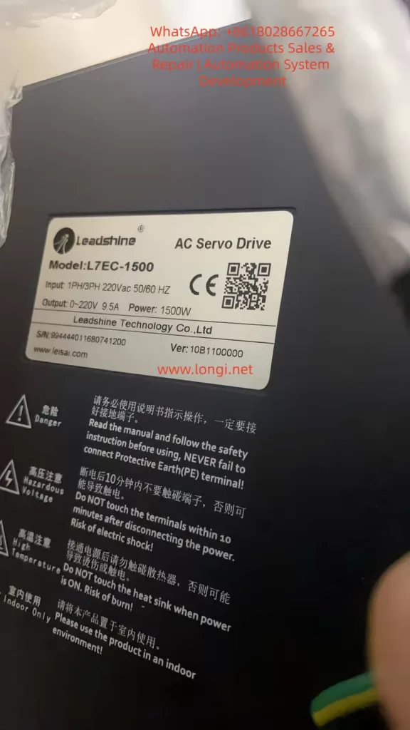
The L7 series belongs to AC servo drives, supporting 220VAC input and a wide power range. The manual emphasizes that improper operation can lead to severe consequences, and users must adhere to safety precautions.
Key Components and Initialization
The key components of a servo system include the drive, motor, and encoder. The drive integrates a DSP processor, and the initialization process involves self-tests, parameter loading, and status monitoring.
Display Panel Basics
The display panel employs a seven-segment LED digital tube, supporting status display, parameter settings, and alarm prompts. Understanding these codes is crucial for diagnosing device status.
Control Modes and Parameter Settings
Servo drives offer control modes including position, speed, and torque modes. Parameter settings are achieved through panel buttons or MotionStudio software.
Safety Guidelines
The manual stresses that product storage and transportation must comply with environmental conditions, and user modifications will void the warranty.
Overview of the L7 Series
Product Features and Updates
The Leadshine L7 series is a fully digital AC servo drive, utilizing TI DSP, supporting stiffness tables, inertia identification, and vibration suppression. The version has evolved from V1.00 to V2.10 with continuous updates.
Application Areas and Manual Structure
The L7 series finds wide applications in PLC control, robotic arms, and other fields. The manual structure covers the preface, safety matters, specifications, installation, wiring, commissioning, and maintenance.
Wiring and Version Descriptions
Wiring includes power, motor, encoder, and I/O ports. The version description indicates program compatibility and content updates.
Display Panel in Detail
Operation Interface and Key Functions
The L7 drive’s operation interface consists of a 6-digit LED digital tube and 5 keys for status display and parameter settings.
Initialization and Monitoring Mode Codes
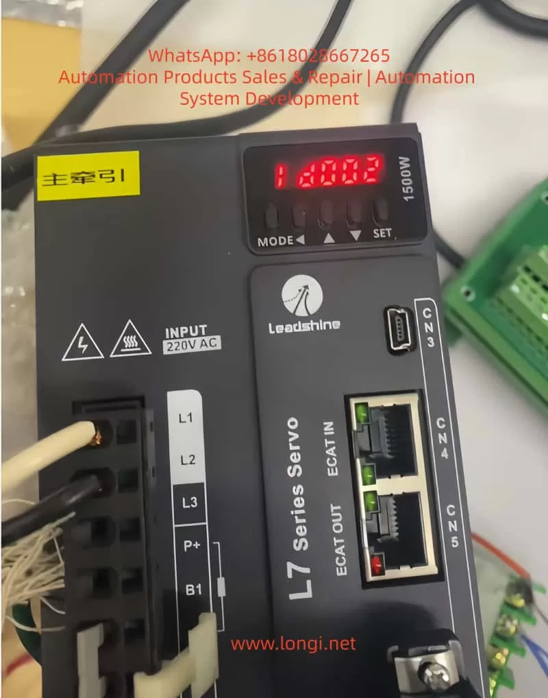
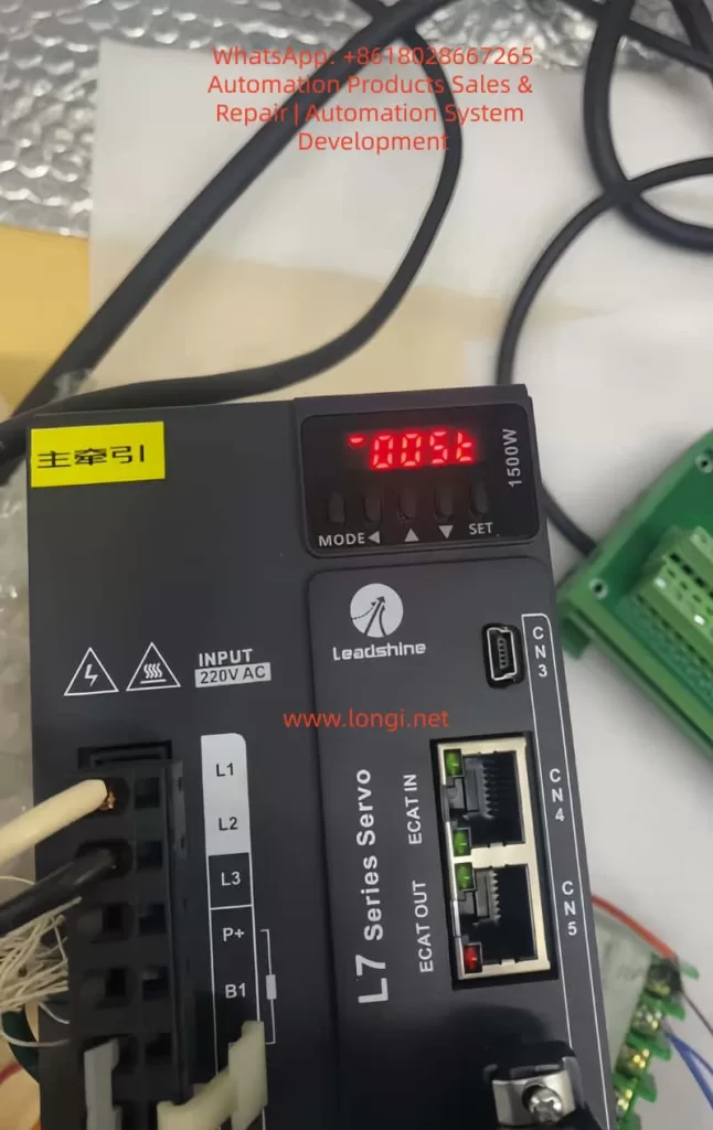
Upon power-on, the panel first displays initialization codes. “1.d002” may be a custom or transient display, and switching to “00ST” indicates a standby state. Monitoring mode codes include position deviation, motor speed, etc.
Alarm Code Interpretation
Alarm codes start with “Er,” and the absence of “Er” indicates normal operation.
Diagnostic Analysis
Core Phenomenon Interpretation
The display showing “1.d002” briefly followed by a switch to “00ST” is a normal sequence. The initialization process includes self-tests and parameter loading.
Potential Causes Explored
Potential causes include normal boot-up, configuration influences, and external factors.
Diagnostic Steps and Methods
Diagnostic steps include checking the display history, software verification, and factory reset.
Troubleshooting
Non-Normal Situation Exclusion Methods
If non-normal, exclusion methods include power supply checks, wiring verification, parameter resets, and software tuning.
Common Faults and Solutions
Common faults such as overcurrent and overload are unrelated to the display sequence.
Applications and Optimization
Case Studies: CNC Machine Tools and Robotic Arms
Case 1: A CNC machine tool uses the L7 to control axes, and a normal startup sequence ensures precision. Case 2: A robotic arm in bus mode uses EtherCAT synchronization to avoid delays.
Optimization Strategies and Future Trends
Optimization strategies include adjusting control modes and vibration suppression. Future trends involve integrating AI tuning.
Conclusion
The transition from “1.d002” to “00ST” indicates a normal state. Mastering diagnostic methods can enhance application efficiency. It is recommended to refer to the manual and technical support to ensure stable system operation.