
I. Product Overview
The DOVOL DV950E series permanent magnet synchronous frequency converter is a general-purpose, high-performance current vector frequency converter. It is mainly used to control and adjust the speed and torque of three-phase AC synchronous motors. This guide provides detailed information on the converter’s functional features, operation methods, parameter settings, and troubleshooting, helping users quickly master the skills of using the equipment.
II. Basic Functions and Wiring
Product Main Features
- Control Modes: Supports sensorless vector control (SVC), sensor-based vector control (FVC), and V/F control.
- Frequency Range: 0 – 500Hz.
- Overload Capacity: 150% of the rated current for 60 seconds, 180% of the rated current for 3 seconds.
- Speed Regulation Range: 1:50 in SVC mode, 1:1000 in FVC mode.
- Built-in PID Regulator: Supports process closed-loop control.
- Multiple Communication Protocols Supported: Modbus, ProfiBus-DP, CANlink, CANopen.
Electrical Installation Precautions
- Main Circuit Wiring: Correctly distinguish between input terminals (R, S, T) and output terminals (U, V, W).
- Braking Resistor: Do not connect the braking resistor directly between the DC bus (+) and (-) terminals.
- Motor Cable Length: When the motor cable length exceeds 100m, install an AC output reactor.
- Grounding: Ensure reliable grounding with a grounding wire resistance of less than 10Ω.
- Power Supply Voltage: Before powering on, ensure that the power supply voltage matches the rated voltage of the frequency converter.
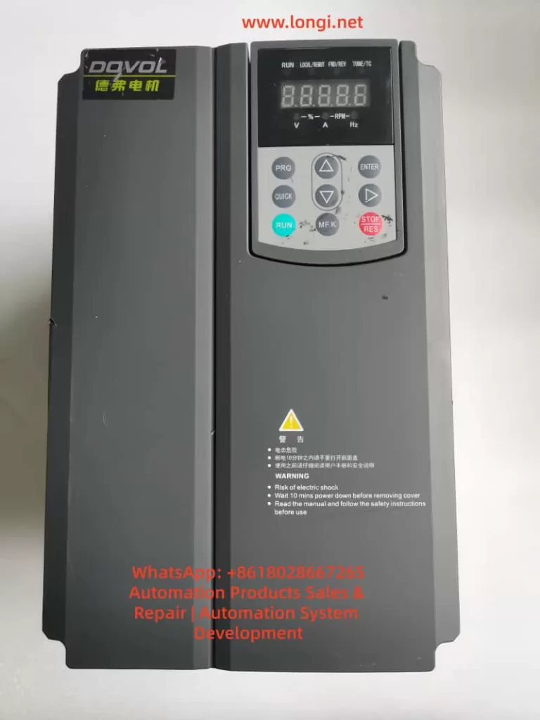
III. Operation Panel Usage
Panel Layout and Indicators
- RUN: Running status indicator (lights up when in operation).
- LOCAL/REMOT: Control mode indicator (off – panel control; on – terminal control; flashing – communication control).
- FWD/REV: Forward/reverse rotation indicator (lights up for reverse rotation).
- TUNE/TC: Tuning/torque control/fault indicator.
- Five-digit LED Digital Display Area.
- Function Keys: PRG (programming), ENTER (confirmation), ▲▼ (increase/decrease), ◄ (shift), etc.
Basic Operation Process
- Enter the parameter setting mode by pressing the PRG key.
- Select the function group using the ▲▼ keys.
- Press ENTER to enter the specific parameter setting.
- After modifying the parameter value, press ENTER to save it.
- Press the PRG key to return to the previous menu.
IV. Core Function Implementation Methods
Motor Forward/Reverse Rotation Control
Method 1: Panel Control
- Set P0-02 = 0 (panel command channel).
- Set the running direction via P0-09 (0 – same direction; 1 – opposite direction).
- Press the RUN key to start and the STOP key to stop.
Method 2: Terminal Control
- Set P0-02 = 1 (terminal command channel).
- Assign DI terminal functions: P4-00 = 1 (DI1 for forward rotation), P4-01 = 2 (DI2 for reverse rotation).
- Control the on/off state of the DI terminals through external switches to achieve forward/reverse rotation.
Method 3: Communication Control
- Set P0-02 = 2 (communication command channel).
- Send forward/reverse rotation commands through communication (requires a communication card).
- Note: To disable reverse rotation, set P8-13 = 1.
Frequency Regulation Methods
Digital Frequency Setting
- Set P0-03 = 0 or 1 (digital setting).
- Set the preset frequency via P0-08.
- During operation, fine-tune the frequency using the panel ▲▼ keys or UP/DOWN terminals.
Analog Frequency Setting
- Set P0-03 = 2 (AI1)/3 (AI2)/4 (AI3).
- Configure the curve characteristics of the corresponding AI input (P4-13 – P4-27).
- Adjust the frequency using an external potentiometer or PLC analog output.
Multi-speed Control
- Set P0-03 = 6 (multi-speed instruction).
- Assign DI terminals as multi-speed instructions (P4-00 – P4-09 = 12 – 15).
- Set the frequency values for each speed segment in the PC group (PC-00 – PC-15).
PID Frequency Regulation
- Set P0-03 = 8 (PID).
- Configure the PID parameters in the PA group.
- Automatically adjust the frequency based on the feedback signal.
Motor Parameter Tuning
No-load Tuning Steps
- Ensure that the motor is mechanically decoupled from the load.
- Correctly input the motor nameplate parameters (P1-01 – P1-05).
- Set P1-37 = 12 (synchronous motor no-load tuning).
- Press the RUN key to start tuning (approximately 2 minutes).
- The parameters are automatically saved after tuning is completed.
Loaded Tuning Steps
- Set P1-37 = 11 (synchronous motor loaded tuning).
- Press the RUN key to start tuning.
- The parameters are automatically saved after tuning is completed.
- Note: Loaded tuning cannot obtain the back electromotive force coefficient, and the control accuracy is slightly lower than that of no-load tuning.
V. Advanced Function Configuration
Frequency Sweeping Function (Textile Applications)
- Set PB-00 = 0 (relative to the center frequency) or 1 (relative to the maximum frequency).
- Set PB-01 (frequency sweeping amplitude), PB-02 (jump amplitude).
- Set PB-03 (frequency sweeping period), PB-04 (triangular wave rise time).
- Control the frequency sweeping pause through the DI terminal (P4-xx = 24).
Fixed-length Control
- Set DI5 function as length counting input (P4-04 = 27).
- Set PB-07 (pulses per meter).
- Set PB-05 (preset length).
- Assign DO terminals as length arrival signals (P5-xx = 10).
Counting Function
- Set DI terminals as counting input (P4-xx = 25) and reset (P4-xx = 26).
- Set PB-08 (preset count value), PB-09 (specified count value).
- Assign DO terminals as counting arrival signals (P5-xx = 8 or 9).
Timing Control
- Set P8-42 = 1 (timing function enabled).
- Set P8-44 (timing operation time) or select AI input via P8-43.
- The equipment automatically stops after reaching the preset time.
VI. Fault Diagnosis and Handling
Common Fault Codes and Handling
| Fault Code | Fault Type | Possible Causes | Handling Methods |
|---|---|---|---|
| Err02 | Acceleration Overcurrent | Short acceleration time/heavy load | Extend the acceleration time P0-17/check the mechanical load |
| Err03 | Deceleration Overcurrent | Short deceleration time | Extend the deceleration time P0-18 |
| Err04 | Constant-speed Overcurrent | Load突变 (Load mutation)/motor short circuit | Check the motor insulation/adjust the torque limit P2-10 |
| Err09 | Undervoltage | Low input voltage/power outage | Check the power supply voltage/set P9-59 for instantaneous power failure without stop |
| Err11 | Motor Overload | Heavy load/undersized motor | Reduce the load/check the rated current setting P1-03 |
| Err14 | Module Overheating | High ambient temperature/poor heat dissipation | Improve the heat dissipation conditions/reduce the carrier frequency P0-15 |
| Err20 | Encoder Fault | Signal interference/wiring error | Check the encoder wiring/set P2-32 = 0 to disable Z correction |
Fault Reset Methods
- Panel Reset: Press the STOP/RES key in the fault state.
- Terminal Reset: Set the DI terminal function to 9 (fault reset).
- Communication Reset: Send a reset command through communication.
Fault Record Inquiry
- Recent Fault: Check P9-16 – P9-22.
- Second Fault: Check P9-27 – P9-34.
- First Fault: Check P9-37 – P9-44.
VII. Maintenance and Upkeep
Daily Inspection
- Check if the cooling fan is operating normally.
- Check for loose wiring terminals.
- Check if the enclosure temperature is abnormal.
- Regularly remove dust from the radiator.
Regular Maintenance
- Check the appearance of electrolytic capacitors every six months.
- Check the insulation resistance annually (measure after powering off).
- Replace the cooling fan every 2 years (depending on the operating environment).
Parameter Backup
- Set PP-01 = 4 (backup user parameters).
- To restore, set PP-01 = 501.
- Restore to factory settings: PP-01 = 1.
VIII. Safety Precautions
- Do not open the cover when powered on. After powering off, wait for 10 minutes before performing wiring operations.
- Do not connect the braking resistor directly to the DC bus.
- Perform an insulation check on the motor before the first use (≥5MΩ).
- Derate the equipment when the altitude exceeds 1000m (derate by 1% for every 100m).
- Derate the equipment when the ambient temperature exceeds 40℃ (derate by 1.5% for every 1℃).
- Do not install capacitors or surge suppressors on the output side of the frequency converter.
This guide provides a detailed introduction to the various function implementation methods of the DV950E frequency converter. When using it in practice, please select the appropriate configuration method according to the specific application scenario. For complex application scenarios, it is recommended to contact the manufacturer’s technical support for more professional guidance.