Posted on

Hach Amtax SC Ammonia Nitrogen Analyzer User Guide

I. Instrument Principle and Features

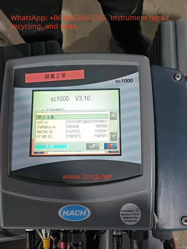
The Hach Amtax SC Ammonia Nitrogen Analyzer is an online analytical device specifically designed for continuous monitoring of ammonium ion concentration in water bodies. It is widely used in wastewater treatment plants, waterworks, surface water monitoring, and industrial process control. Its core measurement principle is the Gas Sensitive Electrode (GSE) method, where a selective electrode reacts with ammonium ions in the sample, and the concentration value is ultimately output in the form of NH₄–N on the controller (sc1000).
Key Technical Features:

  • Wide Measurement Range: Covers three intervals: 0.05–20 mg/L, 1–100 mg/L, and 10–1000 mg/L, allowing flexible application in both low-concentration surface water and high-concentration wastewater scenarios.
  • Fast Response: 90% response time of less than 5 minutes, suitable for real-time monitoring of dynamic water quality.
  • High Precision and Reproducibility: Measurement error is less than ±3% or ±0.05 mg/L (for low ranges), ensuring reliable data.
  • Automation Capabilities: Features automatic calibration, automatic cleaning, and diagnostic functions, significantly reducing manual intervention.
  • Robust Design: Enclosure with an IP55 protection rating and made of UV-resistant ASA/PC material, suitable for harsh outdoor environments.
  • Modular Expandability: Enables data transmission and remote monitoring through the sc1000 controller, supporting single-channel or dual-channel modes.
    Thus, the Amtax SC combines high precision, low maintenance, and strong adaptability, making it a mainstream choice in the field of ammonia nitrogen online monitoring.

II. Installation and Calibration

1. Mechanical Installation

  • Mounting Options: Supports wall mounting, rail mounting, or vertical installation, with wall mounting being the most common. Choose a sturdy, load-bearing wall and ensure smooth routing of surrounding pipes and cables.
  • Weight and Load Requirements: The instrument weighs approximately 31 kg, and the bracket must support a load of ≥160 kg.
  • Installation Environment: Avoid strong vibrations, strong magnetic fields, and direct sunlight. Maintain an ambient temperature range of –20 to 45°C.

2. Electrical Installation

  • Must be performed by qualified personnel to ensure proper grounding and the installation of a residual current device (30 mA RCD).
  • Power is supplied by the sc1000 controller, with voltages of 115V or 230V. The use of 24V controller models is prohibited.
  • All piping and reagent installations must be completed before powering on.

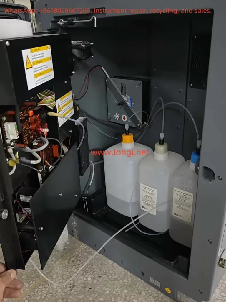
3. Reagent and Electrode Installation

  • Reagent Preparation: Select standard solutions and reagents according to the measurement range. For example, use 1 mg/L and 10 mg/L standard solutions for low ranges, and 50 mg/L and 500 mg/L for high ranges.
  • Electrode Installation: Fill with electrolyte (approximately 11 mL), ensuring no air bubbles remain, and correctly insert the electrode into the electrolysis cell. Replace the membrane cap and electrolyte every 2–3 months.
  • Humidity Sensor: Must be correctly wired to prevent alarms triggered by condensation or liquid leakage.

4. Calibration Procedure

  • Calibration modes include automatic calibration and manually triggered calibration.
  • Set the calibration interval (typically once per day or shorter), and the system will automatically switch standard solutions for electrode correction.
  • After calibration, the system records key parameters such as slope, zero point, and standard solution potential to ensure long-term stable operation.
III. Startup and Operation

1. Startup Steps

  • Ensure all installations (piping, electrical, reagents, electrodes) are complete.
  • Connect the analyzer to the sc1000 controller and power on.
  • Initialize the system: Register the Amtax SC and sampling probe in the controller, execute the “Prepump All” function to fill the piping.
  • Allow a warm-up time of approximately 1 hour for the instrument, reagents, and electrodes to reach operating temperature.
  • Enter the sensor setup menu to confirm the measurement range, output units (mg/L or ppm), and measurement interval.

2. Normal Operation

  • LED Indicators: Green indicates normal operation, orange indicates a warning, and red indicates an error.
  • Measurement Interval: Adjustable from 5 to 120 minutes, depending on application requirements.
  • Data Viewing: The sc1000 controller displays real-time values, historical trends, and alarm status, and can upload data to a monitoring system via a bus interface.
  • Cleaning Function: Set up timed automatic cleaning to ensure the photometer, piping, and electrodes remain clean.

IV. Troubleshooting and Maintenance

1. Routine Maintenance

  • Appearance Inspection: Regularly check for damage to pipes and cables, and confirm the absence of leaks or corrosion.
  • Fan Filter: Clean or replace every 6–12 months to ensure proper heat dissipation.
  • Reagents and Electrodes: Replace reagents every 2–3 months, electrode membrane caps and electrolyte every 2–3 months, and electrodes every 1–2 years, as recommended in Table 5.
  • Cleaning Cycle: Depends on water hardness; typically perform automatic cleaning every 1–8 hours.

2. Common Faults and Solutions

  • Low/High Temperature: If the internal temperature falls below 4°C or rises above 57°C, the system enters service mode. Check the heating or cooling fan.
  • Humidity Alarm: Liquid detected in the collection tray; locate and repair the leak source.
  • Abnormal Electrode Slope: Check the membrane and electrolyte, replace the standard solution; if the issue persists, replace the electrode.
  • Weak Photometer Signal: Trigger cleaning; if unresolved, manually clean or contact a service technician.

3. Long-Term Shutdown and Storage

  • Flush the instrument with distilled water in a circulation mode to empty the pipes and reagent bottles.
  • Remove the electrode, clean it, and reinstall it in the electrolysis cell, keeping it moist during storage.
  • Install transport locks and store in a dry, frost-free environment.

4. Professional Repairs

  • Certain components (such as pumps, compressors, and main circuit boards) must be replaced by the manufacturer or authorized service personnel. Typical service lives: pumps 1–2 years, compressors 2 years, all covered under warranty.

V. Conclusion

The Hach Amtax SC Ammonia Nitrogen Analyzer is a stable and highly automated online monitoring device. It features a scientific principle, clear installation requirements, a straightforward operation process, and comprehensive maintenance methods. By strictly adhering to the user manual and this guide, users can ensure the long-term stable operation of the device, providing reliable data support for water quality monitoring and wastewater treatment process control. Correct installation, regular calibration, and maintenance are key to ensuring the instrument’s long-term stable operation. Users should strictly follow the safety specifications in the operation manual, regularly replace reagents and electrodes, and promptly address fault alarms to ensure measurement accuracy and extend the instrument’s service life.

Posted on

UVP BioDoc-It2 Gel Imaging System: Comprehensive Guide to Specifications, Usage, and Maintenance

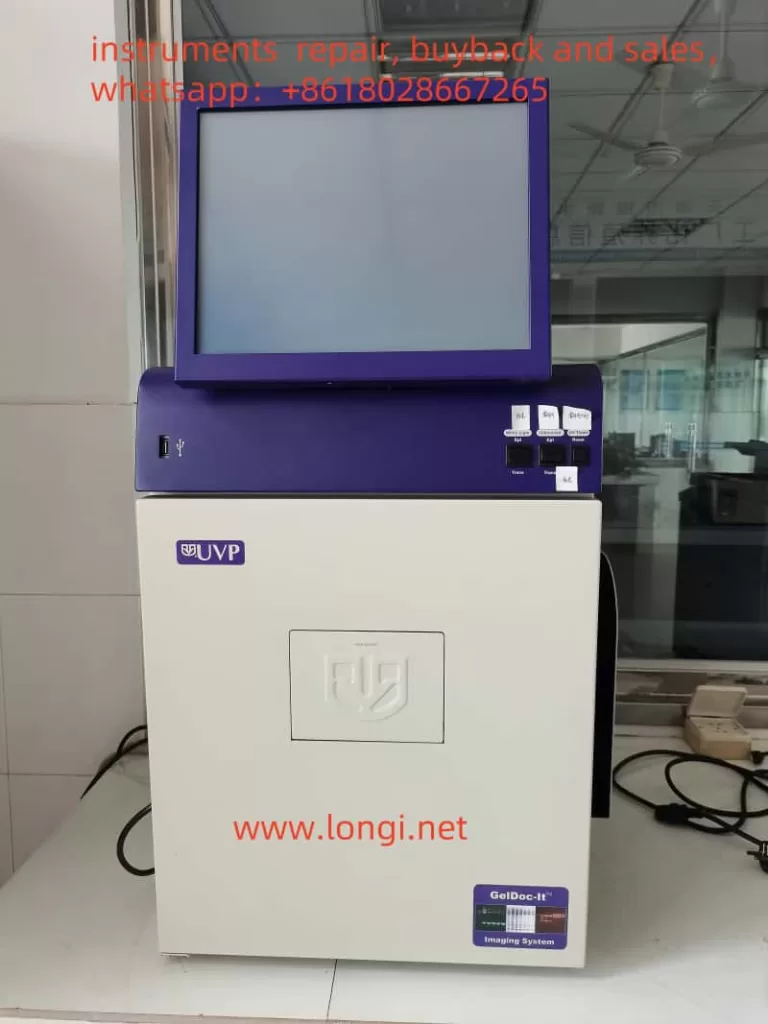
UVP BioDoc-It2 Gel Imaging System

I. Product Overview

The UVP BioDoc-It2 Gel Imaging System is a high-performance biological imaging device produced by Analytik Jena, widely used in fields such as molecular biology, genetics, and biochemistry. This system is primarily utilized for the detection and analysis of nucleic acids and protein gels, featuring easy operation, clear imaging, and versatile functions.

II. Main Technical Parameters

  • Camera: High-resolution digital camera equipped with a high-sensitivity sensor to ensure detection of low-signal samples.
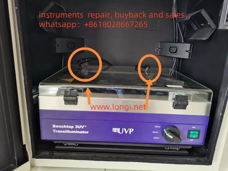
  • UV Transilluminator: Provides multiple wavelengths (254nm, 302nm, 365nm) of UV light sources, suitable for different types of dyes and samples.
  • Filters: High-quality filters ensure the transmission of specific wavelengths of light, enhancing image contrast and clarity.
  • Software: The accompanying VisionWorks LS analysis software supports image capture, processing, and analysis functions, meeting various experimental needs.

III. Usage Methods

  1. Equipment Connection and Startup
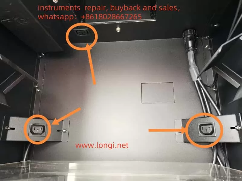
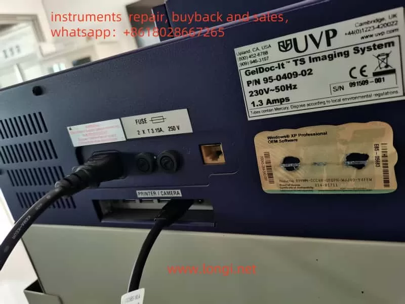
    • Power Connection: Ensure the equipment is connected to a stable power source and check the integrity of the power cord and plug.
    • Equipment Startup: Press the power switch and wait for the system to start up completely.
  2. Sample Preparation and Placement
    • Gel Preparation: Prepare agarose or polyacrylamide gels of appropriate concentration and size according to experimental requirements.
    • Sample Loading: Add samples to the gel lanes and run electrophoresis.
    • Staining: Stain the gel with an appropriate dye (such as ethidium bromide, SYBR Green, etc.).
    • Placement: Place the stained gel on the glass platform of the UV transilluminator, ensuring it is centered and not tilted.
  3. Image Capture
    • Select Light Source: Choose the appropriate wavelength of UV light source based on the characteristics of the dye used.
    • Adjust Parameters: In the VisionWorks LS software, adjust parameters such as exposure time and gain to ensure a clear image.
    • Preview and Capture: Use the software’s preview function to view the real-time image, adjust the focus and aperture until satisfied, and then capture the image.
  4. Image Processing and Analysis
    • Image Enhancement: Use the software’s image enhancement functions, such as adjusting brightness and contrast, to improve image quality.
    • Quantitative Analysis: Utilize the software’s analysis tools to perform quantitative analysis on bands, such as calculating band intensity and molecular weight.
    • Data Export: Export analysis results and images in various formats for report writing and data sharing.
rhdr

IV. Maintenance and Upkeep

  1. Routine Maintenance
    • Cleaning: Regularly clean the glass platform of the UV transilluminator with a soft, lint-free cloth to avoid sample residue affecting experimental results.
    • Inspection: Periodically check the integrity of the power cord, connecting cables, and various components to ensure the equipment is functioning normally.
  2. Lamp Replacement
    • Determine Replacement Timing: Consider replacing the lamp when the brightness of the UV light source significantly decreases or flickers.
    • Replacement Steps:
      • Turn off the power: Ensure the equipment is powered off and unplug the power cord.
      • Disassemble the housing: According to the device manual, disassemble the housing of the UV transilluminator to expose the lamp.
      • Remove the old lamp: Carefully rotate and remove the old lamp, avoiding excessive force that could damage the lamp socket.
      • Install the new lamp: Insert the new lamp into the socket and ensure it is securely installed.
      • Reassemble the housing: Install the housing back and ensure it is securely fixed.
      • Test: Connect the power, start the equipment, and check if the new lamp is working normally.
  3. Software Maintenance
    • Updates: Regularly check and update the VisionWorks LS software to obtain the latest features and fixes.
    • Backup: Regularly back up experimental data and image files to prevent data loss.

V. Safety Precautions

  • UV Protection: Wear protective goggles and gloves during operation to avoid direct exposure of skin and eyes to UV light.
  • Equipment Grounding: Ensure the equipment is properly grounded to prevent static electricity and leakage risks.
  • Ventilation: Use the equipment in a well-ventilated environment to avoid the accumulation of harmful gases.
  • Operation Training: Personnel who have not been trained shall not operate the equipment. Ensure that operators are familiar with the use and maintenance of the equipment.

VI. Common Problems and Solutions

  1. Blurry Images
    • Possible Causes:
      • Incorrect focus adjustment: The camera is not aligned with the sample’s focus, resulting in a blurry image.
      • Uneven sample placement: The gel sample is not placed flat on the UV transilluminator, causing unclear imaging.
      • Stains on the filter surface of the UV transilluminator: Dust, fingerprints, or other contaminants on the filter surface affect light transmission.
      • Stains on the camera lens or filter: Stains on the lens or filter reduce image quality.
      • Environmental light interference: External light enters the imaging system, affecting image quality.
    • Solutions:
      • Adjust the focus: Use the preview function of the VisionWorks LS software to manually adjust the camera focus until the image is clear.
      • Ensure even sample placement: Place the gel sample flat on the glass platform of the UV transilluminator, avoiding tilting or bending.
      • Clean the filter and lens: Gently wipe the filter and camera lens of the UV transilluminator with a lint-free soft cloth to ensure their surfaces are clean and free of stains.
      • Reduce environmental light interference: Operate in a darkroom or shaded environment to ensure the imaging system is not interfered with by external light.
  2. Insufficient Image Brightness
    • Possible Causes:
      • Short exposure time: The camera’s exposure time is set too short, resulting in insufficient image brightness.
      • Aging of the UV lamp: The lamp of the UV transilluminator has been used for too long, and its brightness has decreased.
      • Low dye concentration: Insufficient dye concentration during gel staining results in weak fluorescent signals.
    • Solutions:
      • Extend the exposure time: Appropriately extend the camera’s exposure time in the VisionWorks LS software to increase image brightness.
      • Replace the lamp: If the UV lamp is aged, it is recommended to replace it with a new one to ensure sufficient UV light intensity.
      • Increase dye concentration: Appropriately increase the dye concentration or extend the staining time to enhance the fluorescent signal intensity.
  3. Software Malfunction
    • Possible Causes:
      • Outdated software version: The used version of the VisionWorks LS software is outdated, with compatibility or functional defects.
      • Incorrect software settings: Improper software parameter settings lead to abnormal functions.
    • Solutions:
      • Update the software: Visit the Analytik Jena official website to download and install the latest version of the VisionWorks LS software.
      • Restore default settings: Restore default settings in the software or refer to the user manual to reconfigure software parameters.
  4. Equipment Fails to Start
    • Possible Causes:
      • Power connection issue: The power cord is not properly connected, or the power outlet has no electricity.
      • Blown fuse: The internal fuse of the equipment is blown, causing a circuit interruption.
    • Solutions:
      • Check the power connection: Ensure the power cord is securely connected, the power outlet has electricity, and the voltage meets the equipment requirements.
      • Replace the fuse: Refer to the user manual to check and replace the blown fuse, ensuring the use of a fuse of the same specification.
  5. UV Lamp Does Not Light Up
    • Possible Causes:
      • Damaged or aged lamp: The UV lamp is damaged or has reached its service life.
      • Power issue: The power connection of the UV transilluminator is poor, or the switch is faulty.
    • Solutions:
      • Replace the lamp: Follow the equipment maintenance procedure to replace the UV lamp with a new one.
      • Check the power: Ensure the power connection of the UV transilluminator is normal, and the switch functions properly.

VII. Conclusion

The UVP BioDoc-It2 Gel Imaging System, as a high-performance biological imaging device, plays a crucial role in nucleic acid and protein research. Its high-resolution imaging, easy operation, and versatile analysis capabilities make it an indispensable tool in laboratories. Through proper use and maintenance, researchers can fully leverage the advantages of this system, improving experimental efficiency and data quality.