I. Fault Background and Positioning Principles
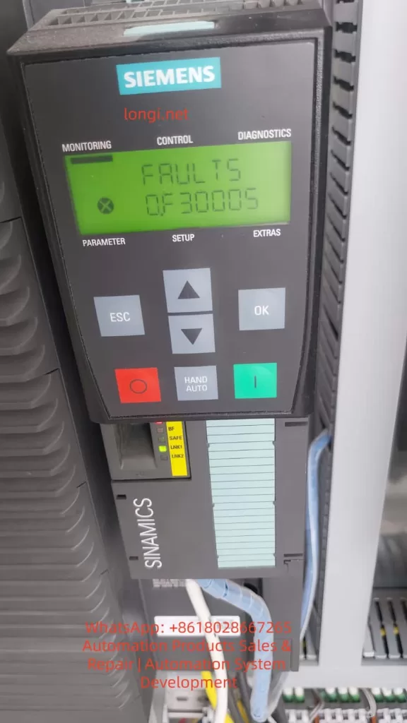
In the Siemens SINAMICS G120 series variable frequency drive system, the fault code F30005 – Power unit overload falls within the range of 30000–30999 and is clearly attributed to the DRIVE-CLiQ power unit (Power Module, PM) itself, rather than the control unit (CU) or the external communication layer. This fault code indicates that the power module has internally determined that its operating state has exceeded the safe operating boundaries, and does not simply refer to motor overload or a load current exceeding the nameplate value.
II. The True Meaning of “Power Unit Overload” in SINAMICS G120
1. Siemens’ Engineering Definition of “Overload”
In the SINAMICS system, “Power Unit Overload” is not a simple I²t overload protection but the result of a multi-dimensional comprehensive assessment, including power device (IGBT) junction temperature models, heat sink temperature rise models, output current time integrals (equivalent thermal loads), abnormal DC bus energy flows, and the coupling effects of switching losses and carrier frequencies. F30005 is the final outcome of a thermal model mismatch or stress overrun in the power module.
2. Relationship with the F3xxxx Coding System
The range 30000–30999 clearly points to the DRIVE-CLiQ power unit, with F30005 being a typical representative within this range. This means that the fault source lies in power modules such as the PM240/PM240-2/PM250, with the CU only responsible for forwarding the fault information. DRIVE-CLiQ communication serves as an information channel and is not the root cause of the fault.
III. Typical Trigger Scenarios for F30005
Scenario 1: Long-Term Operation in the “Hidden Overload Zone” of the Power Module
The operating current does not exceed the rated value, but prolonged operation, high ambient temperatures, and inadequate cabinet ventilation design lead to continuous accumulation in the IGBT junction temperature model, ultimately triggering F30005. This is a thermal design issue, not a parameter issue.
Scenario 2: Low-Speed, High-Torque Operating Conditions
In low-frequency (<10 Hz), high-torque maintenance, vector control/DTC modes, prolonged “holding still” results in a significant increase in IGBT conduction losses, reduced fan speed, decreased cooling capacity, and a thermal model accumulation rate that far exceeds expectations.
Scenario 3: Improper Matching Between the Power Module and the Motor
If the PM power selection is too small, the motor’s rated current is close to the PM’s upper limit, the actual load torque exceeds the design value, or high-inertia mechanical systems are used, the power module will alarm even if the parameters “appear to be fine.”
Scenario 4: Improper Carrier Frequency Settings
Setting the carrier frequency too high (e.g., 8–12 kHz) in pursuit of low noise, combined with high power, leads to increased IGBT switching losses, rising module heat generation, and ultimately triggers F30005.
IV. Why “Restarting Works for a While,” but the Fault Recurs?
The thermal model is reset upon power-off, and the actual IGBT junction temperature drops, temporarily restoring the system’s “safety margin.” However, as long as the operating conditions, cooling conditions, and parameters remain unchanged, the thermal model will accumulate again, and the fault will inevitably reoccur.
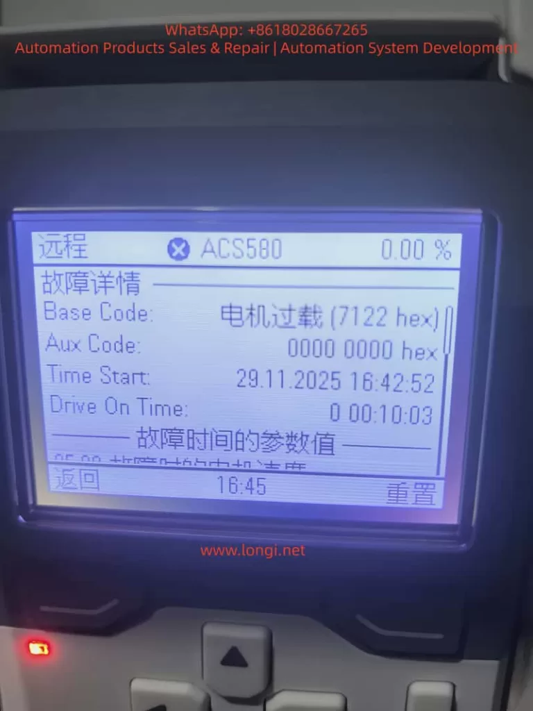
V. The Fundamental Differences Between F30005 and “Motor Overload”
| Comparison Item | Motor Overload | F30005 |
|---|---|---|
| Monitoring Object | Motor | Power Module |
| Judgment Basis | Current/I²t | Thermal Model + Energy |
| Must Have High Current | Yes | Not Necessarily |
| Short-Term Recoverability | Limited | Obvious |
| Root Cause | Mechanical or Load | Electrical + Thermal |
VI. Engineering-Level Troubleshooting Process
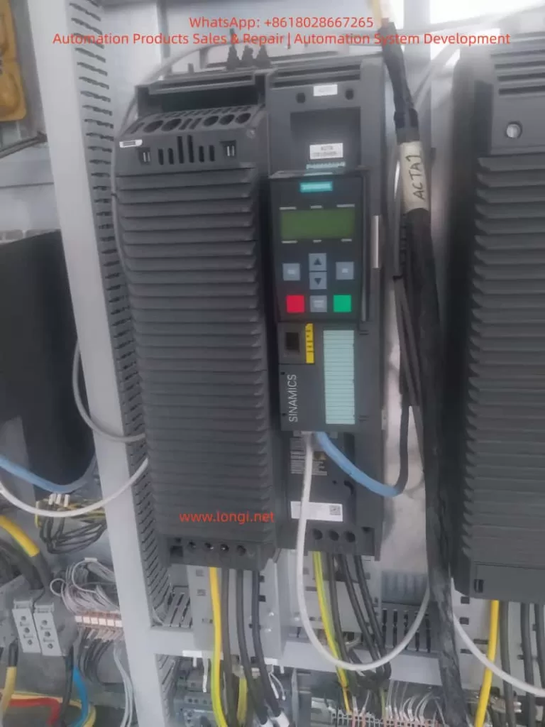
Step 1: Confirm the Power Module Model and Rated Capacity
Check the model and current rating of power modules such as the PM240/PM240-2/PM250 to confirm whether they are operating close to or exceeding 80% of their long-term capacity. Insufficient power module selection is a common cause.
Step 2: Inspect Cabinet Cooling and Environmental Conditions
Focus on the cabinet temperature, whether the air duct is blocked by cables, and whether the PM fan is aged or dusty.
Step 3: Analyze Operating Conditions
Confirm whether there is long-term low-speed, heavy-load operation, frequent starting/stopping, or accumulation of DC braking or regenerative energy.
Step 4: Review Carrier Frequency and Control Modes
Check whether thermal margins have been sacrificed for “quietness” and whether unnecessary high-performance control modes are being used.
VII. Sustainable Solutions
✔ Correct Approaches
- Reduce the carrier frequency to decrease IGBT switching losses.
- Optimize the process operating curve to avoid prolonged low-speed, heavy-load operation.
- Improve cooling conditions, such as clearing air ducts and replacing aged fans.
- Upgrade the power module rating if necessary to increase system redundancy.
✘ Incorrect Practices
- Repeatedly resetting the system while ignoring the root cause.
- Blindly increasing overload parameters to mask the fault.
- Ignoring cabinet thermal design, leading to recurring issues.
- Shifting the blame to the motor, delaying repair timing.
VIII. Conclusion: F30005 is the “Power Module’s Self-Preservation Mechanism”
F30005 is not bad news but a clear indication from the power module that the current system’s thermal-electrical-mechanical balance has been disrupted. Ignoring it may lead to permanent IGBT damage, drive failure, and costs far exceeding those of a reasonable rectification. Therefore, F30005 faults should be taken seriously, and timely troubleshooting and resolution should be carried out.