I. Product Overview and Core Advantages
1. Product Positioning
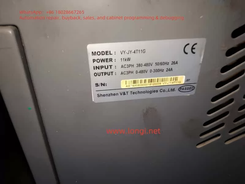
The VY-JY series is a high-performance asynchronous servo drive specifically designed for the hydraulic systems of injection molding machines. It employs sensorless vector control technology to adjust the speed of the oil pump motor to match the flow/pressure requirements of the injection molding process, eliminating overflow energy consumption and achieving a 25%-70% energy savings rate.
2. Technical Highlights
Dual Vector Control Modes:
- Vector Control 1: 180% starting torque at 0.50 Hz, speed regulation range of 1:100, and speed stability accuracy of ±0.5%.
- Vector Control 2: 180% starting torque at 0.25 Hz, speed regulation range of 1:200, and speed stability accuracy of ±0.2% (comparable to DC motor control).
Core Energy-Saving Technologies for Injection Molding:
- Real-time reception of injection molding machine pressure/flow signals to dynamically adjust oil pump speed, eliminating high-pressure overflow losses.
- Support for 3 customizable flow-pressure curves (4-point, 5-segment correction) to adapt to different mold processes.
High Reliability Design:
- Wide voltage range (DC 360-720V) and triple-protection technology (PCB coating, copper busbar plating, and sealed components).
- Short-term overload capacity: 200% rated load for 0.5 seconds, 150% rated load for 1 minute.

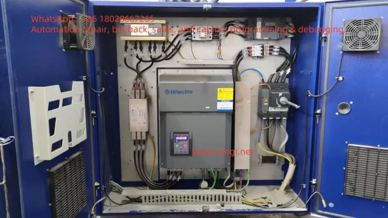
II. Installation and Wiring Specifications
1. Installation Environment Requirements
| Parameter | Standard Value | Remarks |
|---|---|---|
| Ambient Temperature | -10°C to +40°C | Derate rated current by 1% for every 1°C increase above 40°C |
| Humidity | 5% to 95% | Condensation prohibited |
| Altitude | ≤2000 meters | Derate by 1% for every 100 meters above 1000 meters |
| Vibration | ≤15 m/s² (200-500 Hz) | Avoid metal dust/corrosive gases |
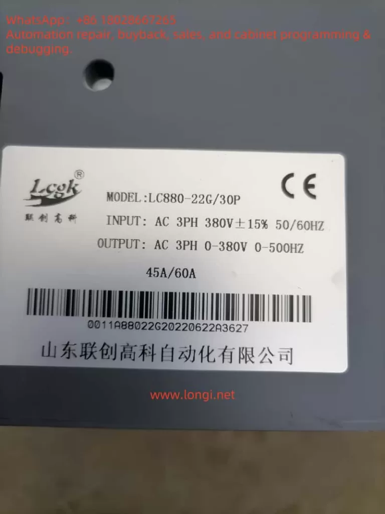
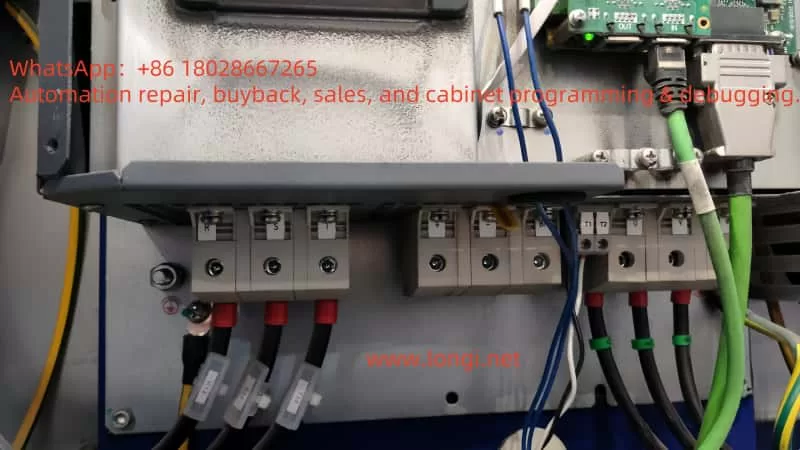
2. Main Circuit Wiring Essentials
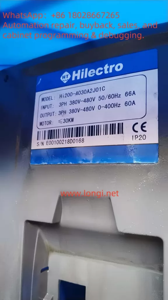
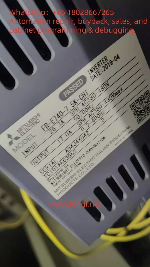
- Power Terminals: Connect R/L1, S/L2, and T/L3 to a three-phase power supply (380-480V ±15%).
- Motor Terminals: Connect U/T1, V/T2, and W/T3 to the motor. Reverse connection or short-circuiting is strictly prohibited.
- Brake Resistor:
- Models from 11-15 kW come with a built-in brake unit (terminals B1/B2) as standard.
- Models above 18.5 kW require an optional brake resistor with a resistance value greater than the lower limit specified in the manual (e.g., ≥7Ω for a 55 kW model).
- Grounding Requirements:
- The PE terminal must be independently grounded (resistance <10Ω).
- The grounding wire diameter should be selected based on power rating (e.g., 35 mm² for a 90 kW model).
3. Control Circuit Wiring
- Analog Inputs:
- AI1/AI2: 0-10V or 0-20mA (selectable via jumpers).
- AI3: -10V to +10V (supports direction control).
- Digital Inputs: X1-X7 support 24VDC switch/pulse signals (up to 50 kHz).
- Communication Interface: Dual 485 ports (Modbus-RTU protocol), supporting master-slave control and parameter reading/writing.
⚠️ Safety Warning:
- Separate or vertically cross the main and control circuit wiring to prevent interference.
- When the motor cable exceeds 100 meters, an output reactor must be installed, and the carrier frequency must be reduced (≤5 kHz).
III. Operation Procedures and Parameter Settings
1. Initial Power-On Operation Procedure
mermaidgraph TD A[Power On] --> B[Restore Factory Parameters P0.01=3] B --> C[Set Motor Nameplate Parameters P9.00-P9.04] C --> D{Can the Load Be Disconnected?} D -->|Yes| E[Rotating Auto-Tuning P9.15=2] D -->|No| F[Stationary Auto-Tuning P9.15=1] E & F --> G[Press RUN Key to Execute Auto-Tuning] G --> H[Set Operating Frequency P0.05] H --> I[Select Control Mode P0.03] I --> J[Start Operation]2. Injection Molding-Specific Function Configuration
Energy-Saving Mode Activation (H0 Group Parameters):
| Function Code | Name | Example Setting | Function Description |
|---|---|---|---|
| H0.00 | Plastic Machine Frequency Setting Mode Selection | 1 | Enable User-Defined 1 |
| H0.03 | Plastic Machine Frequency Setting User-Defined 1 | 0000 | Both Flow and Pressure Signals Are Valid |
| H0.09-H0.16 | Flow-Frequency Curve 1 | A0=0%, B0=0% A3=100%, B3=100% | 4-Point Linear Mapping |
Soft PLC Logic Programming (H1 Group Parameters):
Perform logical operations (AND/OR/NOT) or mathematical operations (addition, subtraction, multiplication, division) on digital/analog quantities, and output the results to the Y terminal or control frequency.
Example: H1.00=111 enables 3-channel logical operations, and H1.01=123 sets X1/X2/X3 as input sources.
3. Key Operating Parameters
| Parameter Group | Function Code | Name | Recommended Value | Impact |
|---|---|---|---|---|
| P0 | P0.08 | Acceleration Time 0 | 20.0s | Extend for large inertia loads |
| P3 | P3.05 | Stopping Method | 2 (Deceleration + DC Braking) | Prevent pump reversal |
| PA | PA.00 | Carrier Frequency | 8.0kHz | Reduce for high-frequency noise-sensitive applications |
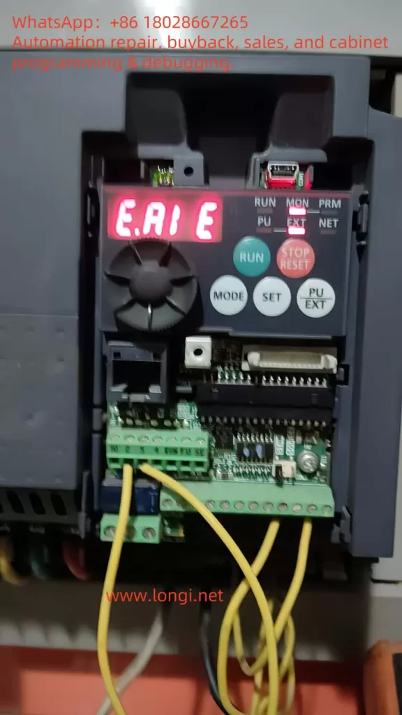
IV. Fault Diagnosis and Maintenance
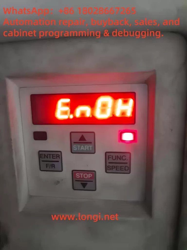
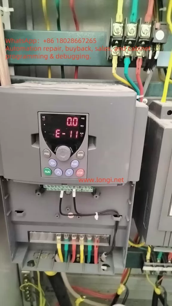
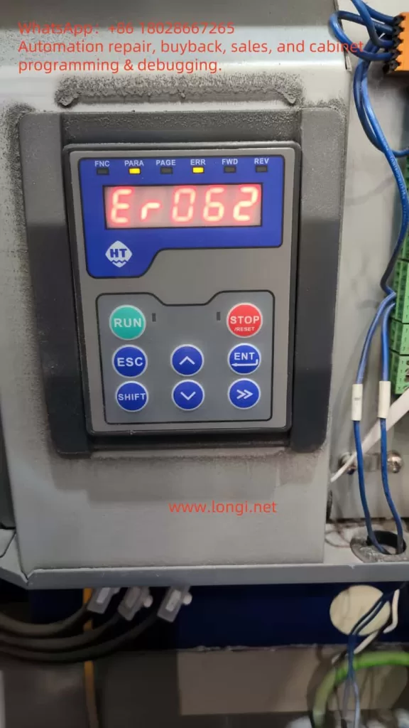
1. Common Fault Handling
| Fault Code | Meaning | Troubleshooting Steps |
|---|---|---|
| E.OC1 | Acceleration Overcurrent | 1. Check for motor cable short-circuits. 2. Extend acceleration time. |
| E.OU | Deceleration Overvoltage | 1. Check brake resistor value. 2. Enable energy dissipation braking. |
| E.PTC | Motor Overheating | 1. Check PTC sensor wiring. 2. Reduce load rate. |
2. Regular Maintenance Items
| Cycle | Item | Operation |
|---|---|---|
| Monthly | Radiator Cleaning | Use compressed air to remove dust (operate with power off). |
| Semi-Annually | Electrolytic Capacitor Inspection | Check for bulging/leakage; replace if capacity drops by ≥20%. |
| Annually | Insulation Resistance Test | Motor winding-to-ground insulation resistance ≥5MΩ (500VDC). |
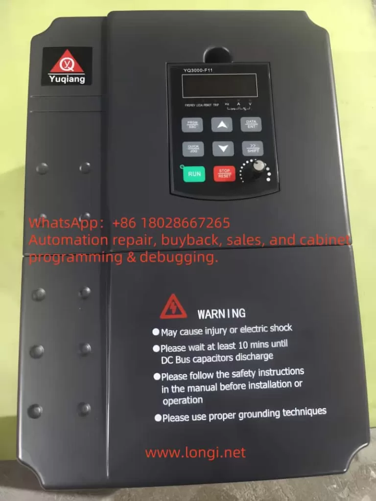
🔧 Maintenance Note: Wait 10 minutes after power-off (until the CHARGE light goes out) before operating to ensure bus capacitor discharge is complete.
V. Energy-Saving Benefit Analysis
Energy Savings Rate Calculation Model:
Energy Savings Rate=(1−Servo System Energy ConsumptionPower Frequency System Energy Consumption)×100%
Influencing Factors:
- Mold Process Speed Value: Energy savings rate ≈70% at 30% speed and ≈25% at 90% speed.
- Net Cooling Time: Energy savings rate decreases without cooling time.
✅ Case Study: Post-retrofit measurements for a 220T injection molding machine at a certain factory:
- Power Frequency Monthly Energy Consumption: 18,600 kWh
- Servo Monthly Energy Consumption: 7,440 kWh
- Energy Savings Rate: 60%
VI. Appendix: Key Parameter Quick Reference Table
| Category | Function Code | Name | Factory Default |
|---|---|---|---|
| Motor Parameters | P9.02 | Rated Speed | 1500 rpm |
| Communication Settings | PC.02 | Local Address | 1 |
| Protection Functions | PA.21 | Auto-Reset Count | 0 (Disabled) |
| Plastic Machine-Specific | H0.34 | AI1/AI2 Extended Input Enable | 0 (Disabled) |
This guide covers the entire process of installation, parameter configuration, fault handling, and energy-saving optimization. It is compiled in conjunction with Chapter 9 (Injection Molding Energy-Saving Principles) and Chapter 10 (Technical Features) of the manual to ensure users quickly master the core applications of the VY-JY series. Before operation, be sure to read the manual’s “Safety Precautions” (Pages 14-16) in detail. Unauthorized operation is strictly prohibited.