1. Introduction
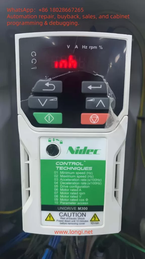
When debugging or repairing the Unidrive M300 variable frequency/servo drive on-site, the sudden illumination of the “inh” (Inhibit) indicator on the panel often catches engineers off guard. This article systematically outlines the fundamental meaning, safety logic, ten common triggering causes, a six-step troubleshooting process, and preventive maintenance strategies for “inh” based on official manuals, Control Techniques FAQs, and years of maintenance experience. It aims to assist peers in quickly locating and eliminating faults, ensuring efficient and safe operation of production lines. The full text is approximately 4,800 words, catering to in-depth reading needs.
2. What is the “inh” State?
As clearly stated in the official “Quick Start Guide” under the “Status indications” table: inh = drive inhibited, output stage disabled; Safe Torque Off (STO) signal not ready or Drive Enable at low level. In this state, the inverter bridge is completely disconnected, and the motor outputs no torque.
Unlike a regular Trip (fault), inh is not logged in the Trip log and cannot be cleared using the reset button. Only by re-establishing the drive enable logic will the LED transition from inh → rdy → StoP/frequency in sequence.
3. Working Principle of STO Function
Safe Torque Off is a safety function defined by EN 61800-5-2. When in the “disable” logic low level (< 5 V), it cuts off all IGBT drive signals, achieving IEC 60204-1 Stop Category 0 “uncontrolled stop.” Its “fail-safe” design ensures that even if a single fault occurs in the inverter stage, MCU, or I/O, the drive cannot be re-energized without authorization.
On the M300, terminals 31-STO1 and 34-STO2 serve as dual-channel redundant inputs; terminals 32 and 33 are their respective independent 0 V references. If either channel loses power, the drive immediately enters the inh state.
4. Ten Common Triggering Causes
| No. | On-site Phenomenon | Possible Cause | Remarks |
|---|---|---|---|
| 1 | Inh immediately upon startup after maintenance | Safety door, emergency stop not reset; no +24 V at 31/34 | First check the safety loop |
| 2 | Random transition to inh during operation | 24 V switching power supply fluctuation < 20 V | Measure T14→32/33 |
| 3 | Inh displayed after performing rotating/stationary autotune with a new motor | Drive automatically inhibits after autotune completion | By design |
| 4 | Inh displayed after restoring default parameters (Def.xx) | Default requires disabling before re-energizing | |
| 5 | PLC outputs Drive Enable but LED remains inh | PLC-COM not sharing 0 V with drive | |
| 6 | Unable to reset after adding a safety relay | Normally closed relay contacts reversed/leakage voltage present | |
| 7 | Loose wiring | Screws at 31, 34 loose, causing intermittent power loss | Recommended torque: 0.2 N·m |
| 8 | 24 V supply connected in series with other devices | Line voltage drop > 5 V triggers disable | |
| 9 | STO module not securely plugged in | Reseat ribbon cable or replace module | Rare occurrence |
| 10 | Firmware detects hardware anomaly | Requires factory repair | “Sto” Trip will also appear |
5. Six-Step Rapid Troubleshooting Process
Measure 24 V:
- Measure the voltage between terminal 14 (+24 V) and 32/33 (0 V); it should be 23–25 V. If insufficient, repair the power supply first.
Confirm STO Channels:
- Short-circuit test: Within safety limits, use a jumper to connect 31 and 34 to 14. If the LED changes to rdy, the issue lies in the external safety chain.
Verify Drive Enable Logic:
- Recommend keeping Pr 11 = 5, with terminals 12/13 for forward/reverse operation, respectively.
Reset Autotune Inhibition:
- After autotune, first disconnect, then reapply 24 V to 31/34, and finally issue the Run command.
Check Wiring Quality:
- Tighten control terminals to 0.2 N·m; check for mixed hard/stranded wires causing screw rebound.
Diagnose External Safety Devices:
- If using safety relays like Pilz or Schneider, check if both channels close synchronously; confirm their status via LEDs or diagnostic contacts.
If the LED remains inh after step 2, it likely indicates a fault with the STO board or mainboard, requiring factory repair.

6. On-site Case Studies
6.1 Injection Molding Machine Retrofit Project
A 75 kW injection molding machine was retrofitted from a Siemens drive to M300. Upon completion, startup often displayed inh. Troubleshooting revealed that PLC-DO and drive 0 V were not sharing a common ground, causing the STO input to detect a 10 V floating ground potential, interpreted as a logic low. Resolving the floating ground issue restored normal operation.
6.2 Textile Winding Line Production
To facilitate maintenance, engineers modified the emergency stop circuit to a single-channel output, connecting only 31 and not 34, resulting in occasional inh states. Based on the STO “disable on low level in either channel” characteristic, connecting 34 to the safety relay’s NO contact stabilized operation.
6.3 Robot Joint Autotune
During a 2 kW servo motor’s rotating autotune, the panel remained inh afterward. The technician mistakenly assumed a fault, but it was actually by design: autotune completion requires re-enabling. Following the reset procedure resolved the issue.
7. Why Can’t You Simply “Clear the Fault”?
As stated in Control Techniques’ official FAQ: INH is not a Trip, so pressing RESET is ineffective; the only solution is to apply 24 V to the STO input. Arbitrarily short-circuiting the safety chain may violate machine CE/UL safety assessments and even incur legal risks.
Therefore, under the framework of industrial safety standards ISO 13849-1 / IEC 62061, it is imperative to identify the root cause of STO disablement, conduct a risk assessment, and confirm the shutdown or restoration of safety devices, rather than merely “silencing” the indication.
8. Preventive Maintenance and Improvement Recommendations
- Independent 24 V Redundant Power Supply: For critical production lines, configure dual isolated power supplies with OR-ing Diode to prevent voltage drops.
- Regular Terminal Tightening: Recommend tightening every six months, especially in high-vibration environments.
- Safety Chain Monitoring: Select safety relays with diagnostic contacts like PNOZmulti or EasyE-Stop to record each opening/closing state.
- Add Voltage Monitoring Signal: Use PLC to monitor T14 voltage and set an alarm for < 20 V to detect power supply failures in advance.
- Parameter Backup: Use AI-Backup SD cards or Machine Control Studio to secure critical parameters, preventing enable logic loss after mistakenly restoring defaults.
- Training and SOP: Develop a “Standard Operating Procedure for STO-Inhibit Resolution” to clarify the sequence of “disconnect, investigate, then re-energize” for on-site personnel.
9. Conclusion
“inh” is not a true fault but rather an active protection mechanism of the Unidrive M300’s safety architecture. A deep understanding of STO dual-channel logic, electrical wiring specifications, and parameter associations can both shorten downtime and enhance overall line safety. We hope this article provides you with a systematic approach and practical tools. If you encounter complex situations on-site, it is recommended to contact the Nidec CT authorized service center for further support. Do not arbitrarily short-circuit the safety loop. Wishing you smooth debugging and safe, efficient production!