
1. Meaning and Essence of the ILF Fault Code
1.1 Definition of the ILF Fault Code
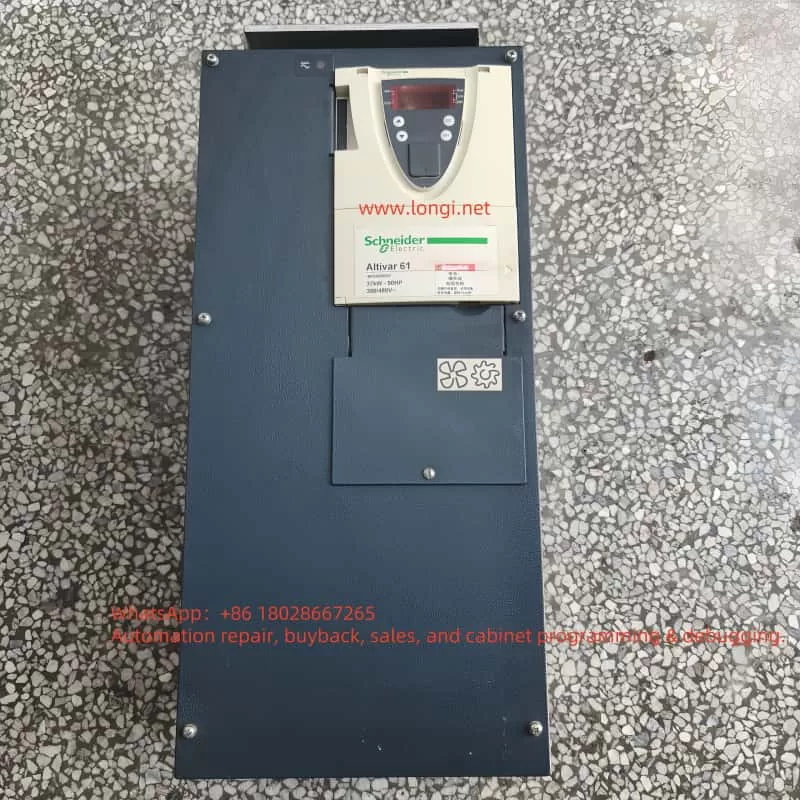
The ILF fault code in Schneider ATV61 inverters stands for “Internal Link Fault.” Specifically, the ATV61 inverter comprises two main components: the control card and the power card. The control card is responsible for logical operations and parameter control, while the power card drives the motor. These two components communicate via an internal communication link, typically a high-speed communication bus. When this communication link encounters issues, the inverter detects the anomaly and triggers the ILF fault code, halting operation to protect the equipment.
1.2 Essence of the ILF Fault
From a technical perspective, the essence of the ILF fault is an interruption or data transmission error in the communication between the inverter’s control card and power card. This communication interruption can be caused by several factors:
- Hardware Issues: Loose, damaged, or poor physical connections (such as communication cables or connectors) between the control card and the power card.
- Component Failure: Hardware damage to the control card or power card, such as burnt chips or aging circuit boards.
- Electromagnetic Interference (EMI): External EMI or poor grounding causing unstable communication signals.
- Firmware Issues: Incompatible or corrupted firmware versions between the control card and power card, leading to the inability to execute communication protocols properly.
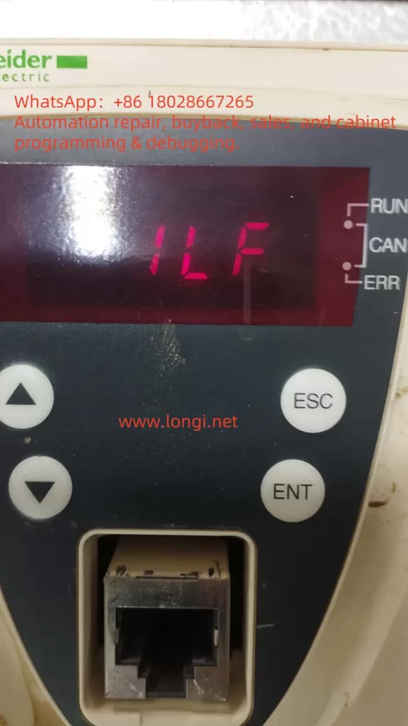
The occurrence of an ILF fault typically results in the inverter stopping operation and alerts the user via the display or status indicators (such as RUN, CAN, and ERR lights).
2. Possible Causes of the ILF Fault
2.1 Hardware Connection Issues
The control card and power card within the ATV61 inverter are connected via dedicated communication cables or connectors. If these connections become loose, poorly contacted, or damaged during operation, communication will be interrupted.
2.2 Control Card or Power Card Failure
The control card and power card are core components of the inverter. If either card’s hardware fails (e.g., chip damage or circuit board burnout), the communication link will not function properly.
2.3 Electromagnetic Interference
Inverters are often installed in industrial environments with high-power equipment, motors, or other sources of electromagnetic interference. If the inverter’s grounding is inadequate or shielding measures are insufficient, communication signals may be disrupted.
2.4 Incompatible or Damaged Firmware
If firmware upgrades fail or the firmware versions of the control card and power card are mismatched, the communication protocol may not execute correctly, triggering the ILF fault.
2.4 Other Potential Factors
- Environmental Factors: High temperatures, humidity, or dust may cause internal components to age or short-circuit.
- Misoperation: Users may accidentally set incorrect parameters or damage hardware during debugging or maintenance.
- Power Issues: Abnormal input power may interfere with the normal operation of the inverter.
3. Handling Methods for the ILF Fault
3.1 Preliminary Checks and Safety Preparations
- Power Off: Turn off the inverter’s power and wait at least 5 minutes to ensure the internal capacitors discharge completely.
- Wear Protective Gear: Wear insulating gloves and shoes, and use appropriate tools.
- Record Fault Information: Record the inverter’s model, firmware version, and fault details.
3.2 Check Hardware Connections
- Check Internal Communication Cables: Ensure cables are not loose, broken, or have poor contact. Reinsert or replace them if necessary.
- Check Connectors: Clean connectors to ensure good contact.
3.3 Investigate Control Card and Power Card Failures
- Replacement Testing: Replace the control card or power card one by one to test if the fault disappears.
- Check Hardware Status: Inspect for obvious physical damage.
3.4 Reduce Electromagnetic Interference
- Check Grounding: Ensure grounding resistance is less than 4 ohms.
- Shielding Measures: Add shielding covers or adjust equipment layout.
- Check Power Quality: Measure input power voltage and frequency, and install power filters if necessary.
3.5 Check Firmware Versions
- View Firmware Information: Confirm that the firmware versions of the control card and power card match.
- Firmware Recovery or Upgrade: Download the latest firmware from Schneider’s official website and upgrade.
3.6 Reset the Inverter
- Power Cycle: Reconnect power and observe if the fault disappears.
- Restore Factory Settings: Reset to factory settings via the menu [1.8 Fault Management] (FLt-) to restore factory settings.
3.7 Contact Technical Support
- Contact Us for Handling: If the above steps fail, seek professional help.
- Provide Information: Prepare the inverter model, firmware version, and fault details.
4. Suggestions for Preventing ILF Faults
- Regular Maintenance: Inspect internal connections and cleanliness every six months.
- Optimize Operating Environment: Ensure proper ventilation and temperature control.
- Standardized Operation: Follow the user manual strictly.
- Monitor Power Quality: Regularly check the stability of the input power supply.
5. Summary
The ILF fault reflects abnormalities in the internal communication link of the ATV61 inverter. Through systematic troubleshooting methods and preventive measures, users can effectively resolve issues and ensure the stable operation of the equipment.