
Introduction
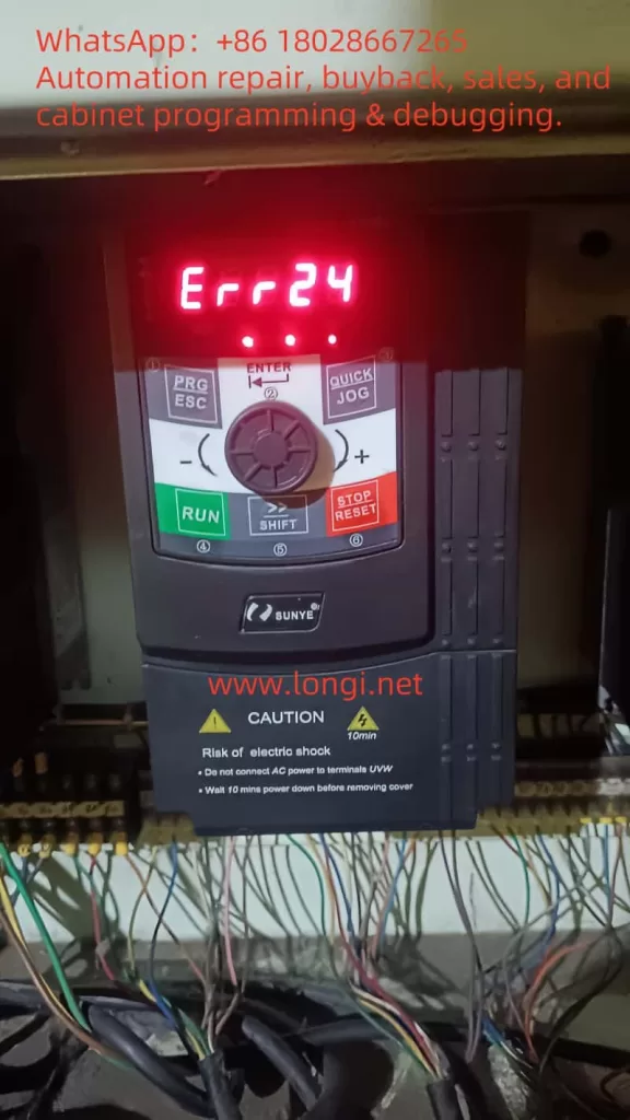
Variable Frequency Drives (VFDs), commonly known as inverters, are essential components in modern industrial control systems. They regulate motor speed and performance to achieve energy efficiency and precise control. However, their complexity can lead to faults, which are often indicated by error codes on the inverter’s display. In the SUNYE CM530 and CM530H series inverters, ERR24 is a frequently encountered fault code, typically associated with an “output side phase error” or “output phase loss.” This article provides a comprehensive guide to understanding ERR24, identifying its causes, troubleshooting the issue, and implementing preventive measures to ensure reliable operation.
Understanding ERR24
The ERR24 fault code likely indicates that the inverter has detected an issue with the output side, specifically a phase sequence error or a missing phase in the three-phase output (U, V, W) to the motor. This disruption can prevent the motor from operating correctly, potentially causing equipment downtime or damage. The error suggests an imbalance in the current or voltage output, which is critical for maintaining stable motor performance. Addressing ERR24 promptly is vital to minimizing disruptions in industrial processes.
Possible Causes of ERR24
Several factors may trigger the ERR24 fault code. Based on common inverter issues and general electrical engineering principles, the following are the most likely causes:
- Output Cable Issues
- Cables connecting the inverter to the motor may become loose, damaged, or disconnected due to vibration, aging, or external factors, resulting in phase loss.
- Insulation damage in cables can cause short circuits between phases or to ground, disrupting the phase sequence.
- Motor-Related Problems
- Internal motor windings may develop open circuits or short circuits due to overheating, aging, or voltage imbalances, leading to unbalanced phases.
- Loose or disconnected motor terminal connections can also trigger ERR24.
- Inverter Internal Faults
- Internal components, such as Insulated Gate Bipolar Transistors (IGBTs) in the inverter’s output module, may fail due to overload or wear, causing phase sequence errors.
- Faults in the control circuit or power board can also contribute to ERR24.
- Environmental Factors
- High dV/dt (voltage change rate) from Pulse Width Modulation (PWM) outputs can stress cable or motor insulation, leading to phase loss.
- Long cable runs (over 50 meters) may require dV/dt or sine wave filters to mitigate voltage spikes.
- System Configuration Issues
- A mismatch between the inverter’s output capacity and the motor’s rated power can destabilize the phase sequence.
- Excessive motor load or frequent start/stop cycles may also induce ERR24.
Troubleshooting ERR24
To resolve the ERR24 fault, follow these systematic steps to identify and address the root cause:
- Inspect Output Cables
- Verify that the U, V, W three-phase cables are securely connected, free from wear, breaks, or burn marks.
- Use a multimeter to test cable continuity and check for open circuits or short circuits.
- For cable runs exceeding 50 meters, consider installing dV/dt or sine wave filters to reduce voltage spikes.
- Examine Motor Connections
- Check that motor terminal connections are tight and secure, tightening them if necessary.
- Measure the resistance of the motor’s three-phase windings (U1-V1, V1-W1, W1-U1) with a multimeter to ensure consistent values. Inconsistent readings may indicate a need for motor repair or replacement.
- Check Inverter Internals
- If cables and motor are intact, the issue may lie within the inverter, such as a faulty IGBT module or control circuit.
- Contact SUNYE’s official after-sales service or a qualified technician to inspect internal components using specialized diagnostic tools.
- Verify System Configuration
- Ensure the inverter’s output capacity matches the motor’s rated power to prevent phase sequence issues.
- Check for excessive motor load and adjust operating parameters or reduce start/stop frequency as needed.
- Assess Environmental Factors
- Confirm that cables meet VFD standards, such as XLPE insulation, and are properly grounded in metal conduits.
- Evaluate the operating environment for high temperatures, humidity, or corrosive gases that could degrade cable or motor insulation.
Troubleshooting Steps Table
| Step | Action | Tools/Notes |
|---|---|---|
| Inspect Output Cables | Check U, V, W cables for secure connections and damage | Multimeter for continuity and insulation |
| Examine Motor | Verify terminal connections; measure winding resistance | Multimeter; ensure balanced resistance |
| Check Inverter Internals | Contact professionals for internal module inspection | Requires specialized equipment; safety first |
| Verify Configuration | Match inverter capacity to motor; adjust load and parameters | Refer to user manual for settings |
| Assess Environment | Ensure VFD-standard cables and proper grounding; check environmental conditions | Use XLPE cables; avoid harsh environments |
Preventive Measures
To minimize the occurrence of ERR24 faults, implement the following preventive strategies:
- Regular Maintenance
- Conduct routine inspections of output cables and motor connections to detect and address wear or looseness.
- Perform preventive motor maintenance, including insulation testing, to identify potential issues early.
- Proper Equipment Selection
- Select an inverter with a capacity that matches the motor’s rated power to avoid compatibility issues.
- Install dV/dt or sine wave filters for long cable runs to protect against voltage spikes.
- Environmental Protection
- Shield cables and motors from high temperatures, humidity, or corrosive environments.
- Use VFD-compliant cables, such as XLPE-insulated cables, and ensure proper grounding.
- Operational Monitoring
- Leverage the inverter’s monitoring features to regularly check output current and voltage balance.
- Address any detected anomalies promptly by adjusting parameters or seeking technical support.
Case Studies
The following real-world examples illustrate how ERR24 faults were diagnosed and resolved:
- Case Study: Cable Insulation Failure
In a manufacturing facility, a CM530H inverter displayed ERR24, and the motor failed to start. Technicians discovered that the cables connecting the inverter to the motor had deteriorated insulation due to prolonged use, causing a short circuit in one phase. Replacing the cables with new, properly grounded ones resolved the ERR24 fault, and the system resumed normal operation. - Case Study: Inverter Component Failure
Another user reported persistent ERR24 errors despite normal cable and motor checks. A professional technician used diagnostic tools to identify a damaged IGBT module in the inverter, caused by overloading. Replacing the module and optimizing the load configuration eliminated the fault.
Conclusion
The ERR24 fault code on SUNYE CM530 and CM530H inverters likely indicates an output side phase sequence error or phase loss, potentially caused by issues with cables, motor windings, internal inverter components, or improper system configuration. By systematically inspecting cables, motor connections, inverter internals, and system settings, users can effectively diagnose and resolve the issue. Preventive measures, including regular maintenance, proper equipment selection, environmental protection, and operational monitoring, are essential to reducing ERR24 occurrences. For complex issues, refer to the SUNYE user manual, particularly Chapter 7, “Fault Diagnosis and Countermeasures,” or contact SUNYE’s official after-sales service for professional assistance. Addressing ERR24 promptly ensures equipment reliability and enhances industrial production efficiency.