
1. Introduction
The TSI VelociCalc 9565 series multifunction air velocity meters, manufactured by TSI Incorporated (USA), are among the most recognized instruments for ventilation testing and cleanroom airflow diagnostics.
Their modular design allows the main unit to connect to a variety of intelligent probes through a standard 7-pin Mini-DIN interface, enabling simultaneous measurements of air velocity, airflow, temperature, humidity, CO, CO₂, VOC, and differential pressure.
This article focuses on a specific configuration:
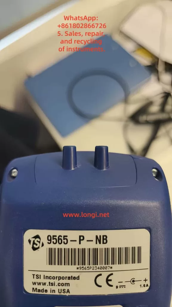
- Main unit: TSI 9565-P-NB, a multifunction meter equipped with a differential-pressure sensor (the “-NB” suffix indicates no Bluetooth).
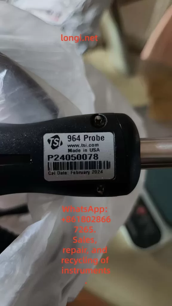
- Probe: TSI 964 hot-film probe for air velocity, temperature, and relative humidity.
Together they provide comprehensive readings of velocity, volumetric flow, temperature, humidity, and static/differential pressure, widely used in:
- Fume-hood face-velocity tests;
- Cleanroom laminar-flow verification;
- HVAC air-balancing and commissioning;
- Energy-efficiency assessments of ventilation systems.
2. Working Principle and Structural Overview
2.1 Hot-film anemometry
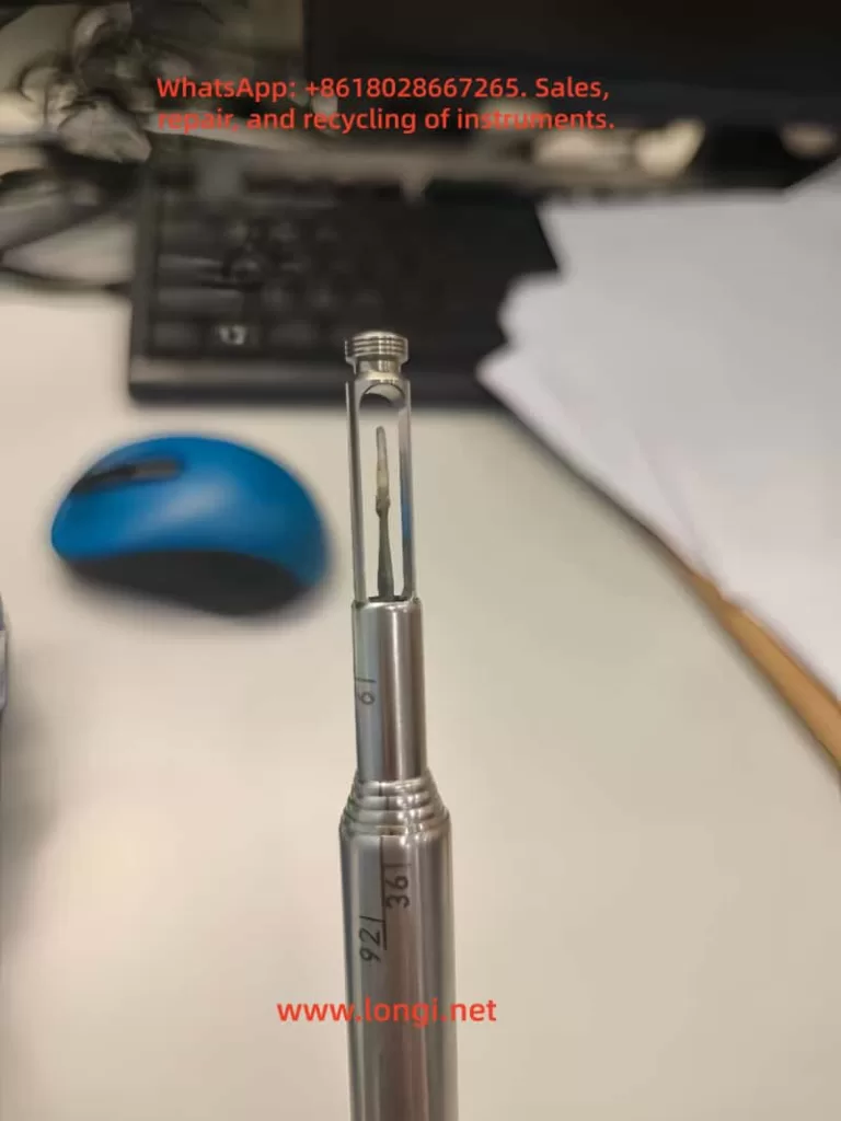
The 964 probe employs a constant-temperature hot-film anemometer. Its sensing element is a precision platinum film that is electrically heated above ambient temperature.
- When air passes over the sensor, convective cooling occurs;
- The electronic bridge circuit maintains a fixed temperature difference ΔT;
- The current required to maintain ΔT is proportional to the square of air velocity;
- The resulting signal is linearized and temperature-compensated to yield the velocity reading (m/s).
The probe also houses a temperature and humidity module, ensuring density compensation and stable performance over a wide range of conditions.
2.2 Differential-pressure module
The 9565-P-NB main unit integrates a ±15 in H₂O (±3735 Pa) differential-pressure sensor.
Through the positive (+) and negative (–) ports, the meter can measure static or differential pressure and compute velocity using a Pitot tube.
Accuracy is specified as ±1 % of reading ±1 Pa.
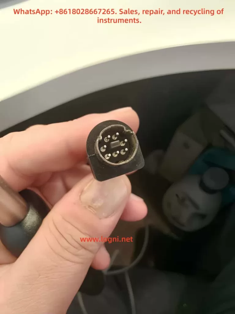
2.3 Probe-to-main-unit interface
The 7-pin Mini-DIN connector at the base of the instrument provides:
- +5 VDC power to the probe;
- Analog signal inputs (velocity, temperature, humidity);
- A digital line for probe identification and calibration coefficients.
Once connected, the main unit automatically reads the probe’s ID EEPROM, displays its model, and activates relevant measurement menus.
If this recognition fails, the instrument shows “Probe Error” and all velocity-related readings remain at 0.00 m/s.
3. Normal Operation Guidelines
3.1 Power-up and warm-up
According to the manual (Chapter 3), the instrument should warm up for about five minutes after power-on before performing pressure zeroing.
This stabilizes the internal sensors and reference voltages.
3.2 Probe orientation and insertion
- The orientation dimple on the probe must face upstream.
- At least 3 in (7.5 cm) of the probe should be exposed to the airflow to ensure that both the temperature and humidity sensors are fully in the airstream.
- Extend the telescopic rod by pulling on the metal tube, never by the cable, to avoid internal wire breakage.
3.3 Display configuration
In the Display Setup menu, up to five parameters can be shown simultaneously (one primary in large font and four secondary).
Typical configuration:
- Primary: Flow (L/s or CFM) or Velocity (m/s or fpm)
- Secondary: Pressure, Temperature, Humidity, Barometric Pressure
Note: “Pitot Velocity” and “AF Probe Velocity” cannot be active at the same time; only one may be ON or set as PRIMARY.
4. Root-Cause Analysis of “Zero Airflow / Zero Velocity” Symptoms
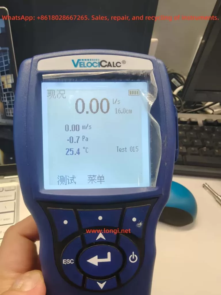
A frequently reported issue is that the display suddenly shows 0.00 m/s velocity and 0.00 L/s flow, while pressure values remain valid.
Based on the manual and field experience, the following causes are most probable.
4.1 Probe recognition failure (most common)
If the main unit cannot read the probe’s EEPROM data, only built-in channels (pressure, temperature, baro) appear, while velocity stays at zero.
The troubleshooting table lists:
Symptom: Probe plugged in, but instrument does not recognize it.
Cause: Probe was inserted while instrument was ON.
Action: Power OFF the unit and turn it ON again.
If the problem persists:
- Connector pins may be oxidized or bent;
- The probe ID circuit or EEPROM may be defective.
4.2 Burned or open-circuit hot-film element
Inside the 964 probe, the micro-thin film (<100 µm) can be destroyed by high temperature, moisture, or dust contamination.
Typical signs:
- The probe model appears correctly in the menu;
- All velocity readings remain 0.00;
- No error message displayed.
Measuring resistance between signal pins with a multimeter helps confirm: an open circuit indicates sensor burnout.
4.3 Incorrect measurement setup
If “Velocity” or “Flow” parameters are disabled in the Display Setup, or if Flow is set as PRIMARY without enabling Velocity as a secondary, the display will not show airflow data.
4.4 Cable or connector damage
Frequent bending or improper storage can break internal wires.
Symptoms include intermittent readings when the cable is moved or total loss of signal.
4.5 Faulty probe port on the main unit
When even a known-good probe is not recognized, the main unit’s connector solder joints or signal amplifier may be defective.
The manual specifies: “Factory service required on instrument.”
5. Systematic Troubleshooting Procedure
| Step | Inspection | Expected Result | Corrective Action |
|---|---|---|---|
| ① | Re-plug probe with power off | Unit recognizes probe after restart | If normal → software/recognition issue |
| ② | Check “Probe Info” menu | Displays “964 Probe SN xxxx” | If blank → contact/ID circuit fault |
| ③ | Verify Display Setup | Velocity = ON, Flow = ON | If still 0 → hardware failure |
| ④ | Swap probe | New probe works | Original probe damaged |
| ⑤ | Measure pin resistance | Several hundred–kΩ | Open circuit → hot-film burned |
| ⑥ | Restore factory settings / calibration | Reset configuration | If unchanged → return for service |
6. Maintenance and Calibration Recommendations
6.1 Routine care
- Keep probes clean; avoid oily or dusty airflows.
- After use, gently blow dry air across the sensor head.
- Store in a dry environment, away from direct sunlight.
- Remove batteries during long-term storage to prevent leakage.
6.2 Calibration interval
TSI recommends annual factory calibration to maintain traceable accuracy.
Field calibration via the CALIBRATION menu is possible but only for minor adjustments; full calibration must be performed by TSI or an authorized lab.
6.3 Typical calibration specifications
| Parameter | Range | Accuracy |
|---|---|---|
| Velocity | 0 – 50 m/s | ±3 % of reading or ±0.015 m/s |
| Temperature | –10 – 60 °C | ±0.3 °C |
| Relative Humidity | 5 – 95 % RH | ±3 % RH |
| Differential Pressure | ±3735 Pa | ±1 % of reading ± 1 Pa |
7. Mechanism of Hot-film Probe Failure
Hot-film velocity sensors are extremely sensitive and delicate.
Typical failure mechanisms include:
- Burnout of heating element — due to transient over-current or contact bounce;
- Surface contamination — dust or oil alters thermal transfer, causing drift;
- Condensation — moisture films short or isolate the element;
- Cable fatigue — repeated bending leads to conductor breakage.
Failures 1 and 4 are the primary causes of complete loss of velocity signal (“0 m/s”).
During repair, check:
- Continuity between connector pins and the sensor head;
- Visual inspection for dark or cracked sensing film;
- Cross-test using another known-good probe.
8. Case Study: Field Repair Example
Background
A laboratory used a TSI 9565-P-NB + 964 probe to measure fume-hood airflow.
After about three years of service, the display suddenly showed:
Pressure fluctuating normally, but velocity = 0.00 m/s and flow = 0.00 L/s.
Diagnosis
- Probe information visible → communication OK.
- Re-plugging did not help.
- Sensor head inspection revealed blackened film.
- Pin resistance = open circuit.
Resolution
- Replaced the 964 probe with a new one.
- Instrument operated normally.
- Post-calibration deviation < 1.8 %.
Conclusion: The zero-airflow symptom was caused by an open-circuit hot-film element.
9. Using Differential-Pressure Mode as Backup
Even when the velocity probe fails, the 9565-P-NB can still measure airflow via Pitot tube + pressure ports:
- Connect Pitot total pressure to “+” port and static pressure to “–”;
- Select Flow Setup → Pressure/K-factor and input duct dimensions;
- The instrument converts ΔP to velocity using standard equations.
This method provides a temporary substitute for velocity readings until the probe is repaired.
10. Safety and Usage Notes
- Avoid electrical hazards: never use near live high-voltage sources.
- Do not open the case: user disassembly voids warranty.
- Operating limits:
- Main unit: 5 – 45 °C
- Probe: –10 – 60 °C
- Maximum overpressure: 7 psi (48 kPa); exceeding this may rupture the pressure sensor.
11. Conclusion
The TSI 9565-P-NB VelociCalc is a high-precision, versatile instrument integrating differential-pressure, velocity, and humidity measurements in one compact platform.
However, in practical field use, the common “airflow = 0” fault is rarely caused by the main unit.
Instead, it almost always results from probe recognition failure or hot-film sensor damage.
Adhering to proper operating procedures—power-off insertion, warm-up before zeroing, periodic cleaning, and annual calibration—greatly extends probe life and maintains accuracy.
For maintenance engineers, understanding the signal flow and failure signatures enables quick fault localization and minimizes downtime.
For facility managers, implementing a calibration and maintenance log ensures data reliability for HVAC system validation.