
I. Operation Panel Functions and Basic Settings
1.1 Introduction to Operation Panel Functions
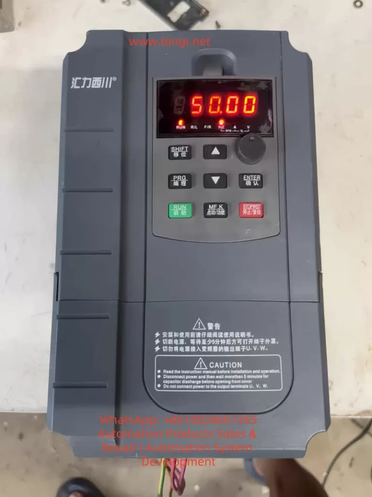
The operation panel of the XC-5000 series frequency converters adopts a three-level menu structure, with the main functional components including:
LED Display Area:
- 5-digit LED Digital Tube: Displays set frequency, output frequency, monitoring data, and alarm codes.
Function Indicator Lights:
- RUN: Indicates the running status.
- LOCAL/REMOT: Indicates the control mode (panel/terminal/communication).
- FWD/REV: Indicates forward/reverse rotation.
- TUNE/TC: Indicates tuning/torque control/fault status.
Key Functions:
- Programming Key (PRG): Enters/exits the first-level menu.
- Confirm Key (ENTER): Enters menus/confirms parameters.
- Increment/Decrement Keys (▲/▼): Increases/decreases data.
- Shift Key (◄): Selects display parameters/modification positions.
- Run Key (RUN): Controls keyboard operation.
- Stop/Reset Key (STOP/RES): Stops operation/resets faults.
- Multi-Function Selection Key (MF.K): Defines functions according to F7-01.
1.2 Parameter Initialization Settings
Restore Factory Parameters (excluding motor parameters):
- Set FP-01 = 1 and confirm.
Clear Operation Record Information:
- Set FP-01 = 2 and confirm.
Restore User Backup Parameters:
- Set FP-01 = 501 and confirm.
Notes:
- Initialization operations must be performed in the stop state.
- After initialization, running parameters need to be reset.
- In vector control mode, motor parameter identification needs to be redone.
1.3 Password Setting and Management
Setting a Password:
- Enter the function code FP-00 and set a 4-digit numerical password (1-65535), then confirm.
Password Protection Activation:
- Password protection takes effect after exiting the function code editing state.
Canceling Password Protection:
- Use the password to enter parameter settings and set FP-00 to 0, then confirm.
1.4 Parameter Access Restriction Settings
Function Group Display Control (FP-02):
- Units digit: U group display selection.
- Tens digit: A group display selection.
Personalized Parameter Group Display Control (FP-03):
- Units digit: User-defined parameter group display selection.
- Tens digit: User-modified parameter group display selection.
Function Code Modification Attribute (FP-04):
- Sets whether parameters can be modified (0 for modifiable/1 for non-modifiable).
Manufacturer Parameter Protection:
- Parameters marked with “*” are prohibited from being modified by users.
II. External Terminal Control and Speed Adjustment Settings
2.1 External Terminal Forward/Reverse Rotation Control
Hardware Wiring:
- Control power wiring: +24V-COM provides +24V power.
- Control signal wiring (two-wire control):
- DI1-COM: Forward rotation signal input.
- DI2-COM: Reverse rotation signal input.
Parameter Settings:
- Command source selection: F0-02 = 1.
- Terminal function definition: F4-00 = 1 (DI1 for forward rotation), F4-01 = 2 (DI2 for reverse rotation).
- Terminal command mode: F4-11 = 0.
- Reverse rotation control enable: F8-13 = 0.
2.2 External Potentiometer Speed Adjustment Settings
Hardware Wiring:
- Connect the two ends of the potentiometer to +10V and GND, and connect the sliding end to AI1-GND.
- Recommended potentiometer specifications: Resistance 1kΩ-5kΩ, power 0.5W or above.
Parameter Settings:
- Frequency source selection: F0-03 = 2.
- AI curve settings: F4-13 = 0.00V, F4-14 = 0.0%, F4-15 = 10.00V, F4-16 = 100.0%.
- Frequency range limitation: F0-10 = 50.00Hz, F0-12 = 50.00Hz, F0-14 = 0.00Hz.
III. Fault Diagnosis and Handling
3.1 Common Fault Codes and Solutions
| Fault Code | Fault Type | Possible Causes | Solutions |
|---|---|---|---|
| ERR02 | Acceleration Overcurrent | Load mutation, short acceleration time | Check the load, increase the acceleration time F0-17 |
| ERR03 | Deceleration Overcurrent | Short deceleration time, large load inertia | Increase the deceleration time F0-18, install a braking resistor |
| … | … | … | … |
| ERR20 | Encoder Fault | PG card fault, wiring error | Check the encoder wiring, set the F1-36 detection time |
3.2 Fault Information Query and Reset
Fault History Query:
- F9-14 to F9-16: Record the types of the last three faults.
- F9-17 to F9-46: Record the operating status parameters at the time of the fault.
Fault Reset Methods:
- Panel reset: Press the STOP/RES key.
- Terminal reset: Set the DI terminal to 9.
- Communication reset: Send a reset command through Modbus communication.
3.3 Fault Protection Action Settings
Fault Action Selection 1 (F9-47):
- Units digit: Motor overload action.
- Tens digit: Input phase loss action.
Fault Action Selection 2 (F9-48):
- Units digit: Encoder fault action.
- Tens digit: Parameter read/write abnormal action.
Fault Action Selection 3 (F9-49):
- Units digit: Custom fault 1 action.
- Tens digit: Custom fault 2 action.
IV. Advanced Functions and Application Examples
4.1 Multi-Motor Control Function
Motor Parameter Group Selection:
- Select the current motor parameter group using F0-24.
Motor Parameter Settings:
- First group: F1 group (motor parameters), F2 group (vector parameters).
- Second group: A2 group (motor parameters), A5 group (vector parameters).
Switching Notes:
- Switching must be performed in the stop state.
- After switching, check the motor rotation direction.
4.2 PID Control Function Application
Basic Parameter Settings:
- FA-00: PID setpoint source selection.
- FA-02: PID feedback source selection.
PID Parameter Settings:
- FA-05: Proportional gain Kp1.
- FA-06: Integral time Ti1.
- FA-07: Differential time Td1.
4.3 Communication Function Configuration
Basic Parameter Settings:
- Fd-00: Baud rate setting.
- Fd-01: Data format.
- Fd-02: Local address.
Communication Control:
- Run command: Communication address 0x1001.
- Frequency setpoint: Communication address 0x1000.
V. Maintenance and Upkeep
5.1 Daily Maintenance Points
Regular Inspection Items:
- Check the operation of the cooling fan.
- Remove dust from the radiator.
- Check the wiring terminals.
- Check the electrolytic capacitors.
Maintenance Cycle Recommendations:
- Daily: Check the operating status.
- Monthly: Clean the radiator.
- Annually: Conduct a comprehensive inspection.
5.2 Long-Term Storage Notes
Storage Environment Requirements:
- Temperature: -20°C to +60°C.
- Humidity: ≤95%RH (no condensation).
Inspection Before Reuse:
- Measure the insulation resistance of the main circuit.
- Check the control board.
5.3 Lifespan Prediction and Replacement
Lifespan Reference for Wear Parts:
- Electrolytic capacitors: Approximately 8-10 years.
- Cooling fans: Approximately 30,000-50,000 hours.
Replacement Notes:
- Cut off the power supply and wait for 10 minutes before operation.
- After replacement, check the parameter settings.
Conclusion
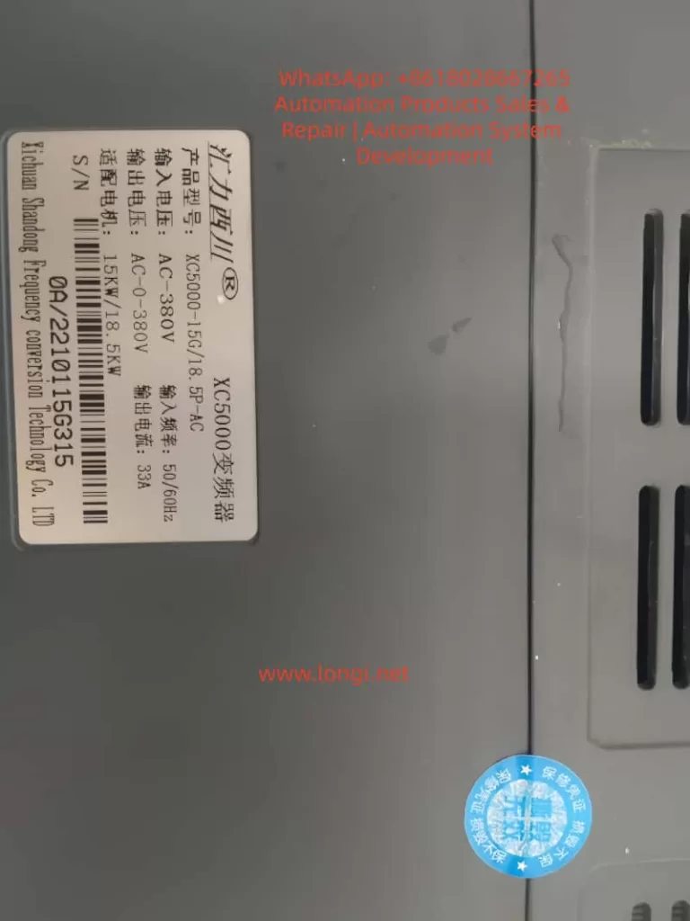
The XC-5000 series frequency converters are powerful and have superior performance. Through this guide, users can comprehensively master core skills such as operation panel usage, parameter settings, external control, and fault diagnosis. Correct installation, parameter settings, and maintenance are key to ensuring the long-term stable operation of the frequency converters. It is recommended that users refer to this guide and make appropriate adjustments according to specific working conditions to fully leverage the performance advantages of the XC-5000 frequency converters.