
I. Inverter Operation Panel Function Introduction and Basic Settings
1.1 Operation Panel Function Overview
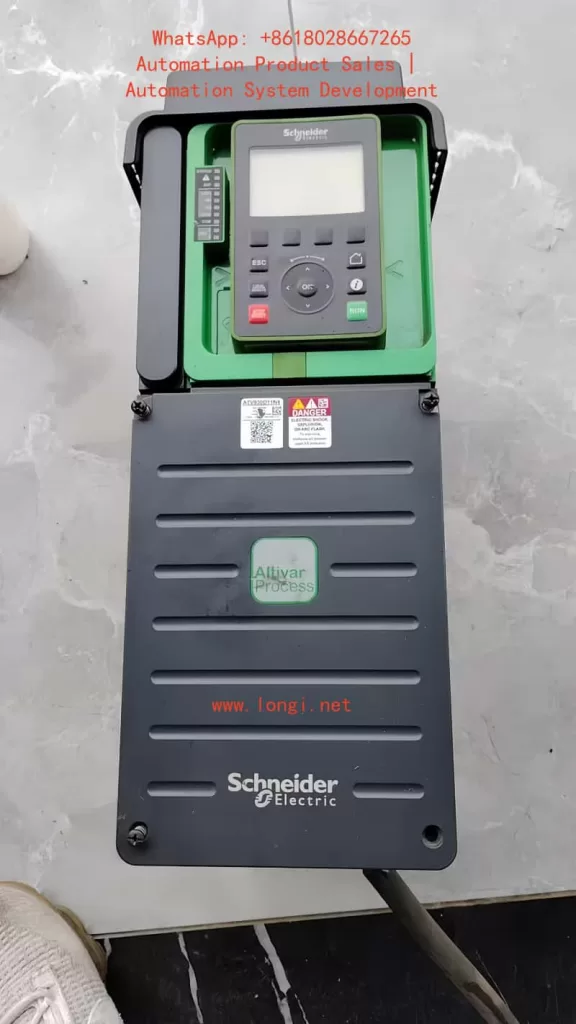
The Schneider ATV930 series inverters come standard with a graphical display terminal (VW3A1111), which includes the following functions:
Button Functions:
- STOP/RESET Button: Issues stop commands/performs fault resets
- LOCAL/REMOTE Button: Switches between local and remote control
- ESC Button: Exits menus/parameters or cancels current modifications
- F1-F4 Function Buttons: Access inverter identification, QR codes, quick browsing, and submenus
- Touch Wheel/OK Button: Saves current values or accesses selected menus/parameters
- RUN Button: Executes run functions (requires configuration)
Display Screen Areas:
- Display Line: Configurable to show content such as inverter status and motor frequency
- Menu Line: Shows the current menu or submenu name
- Four-Region Labels: Quick access via F1-F4 buttons
LED Indicators:
- STATUS LED: Green flashing indicates standby, green solid indicates running, red indicates fault
- Warning/Error LED: Yellow indicates warning, red indicates error
- ASF LED: Indicates activation of safety functions
1.2 Password Setting and Management
Setting a Password:
- Enter the [My Preferences] MYP – [Password] COd menu
- Set a 6-character password (spaces allowed)
- Confirm and save; the password takes effect immediately
Removing a Password:
- Enter the [My Preferences] MYP – [Password] COd menu
- Enter the current password
- Clear the password field and confirm
Password Protection Features:
- Locks after 5 incorrect attempts; requires administrator reactivation
- Recommended to change the password every 90 days
- Use dedicated passwords (do not reuse personal passwords)
1.3 Parameter Access Restriction Settings
Setting Access Levels:
- Enter the [My Preferences] MYP – [Access Level] LAC menu
- Choose between [Standard Permission] Std or [Expert Permission] EPr
- Expert permission allows access to all parameters
Parameter Visibility Control:
- Enter the [My Preferences] MYP – [Parameter Access] – [Visibility] VIS menu
- Hide non-essential parameters to simplify the interface
Restricted Parameter Settings:
- Enter the [My Preferences] MYP – [Restricted Parameters] PPA menu
- Select parameters that require restricted access
1.4 Restoring Factory Parameter Settings
Complete Restoration Method:
- Enter the [File Management] FMt – [Factory Settings] FCS menu
- Select the [Macro Configuration] Ini option
- Confirm execution; all parameters will be restored to factory values
Selective Restoration:
- View recently modified parameters through the [Modified Parameters] LMd menu
- Manually restore each parameter to its factory value
Verification After Restoration:
- Check key parameters such as [Motor Standard Voltage] bFr and [Motor Control Type] Ctt
- Confirm that [Self-Tuning Status] tUS displays [Not Tuned] tAb
II. External Terminal Control and HMI Speed Regulation Implementation
2.1 External Terminal Forward/Reverse Control Configuration
Basic Wiring Schemes:
- 2-Wire Control Mode (Level Control):
- DI1: Forward run (1 = run, 0 = stop)
- DI2: Reverse run (1 = run, 0 = stop)
- Set [2/3-Wire Control] tCC to [2-Wire Control] 2C
- 3-Wire Control Mode (Pulse Control):
- DI1: Stop (normally closed contact)
- DI2: Forward pulse
- DI3: Reverse pulse
- Set [2/3-Wire Control] tCC to [3-Wire Control] 3C
Parameter Configuration Steps:
- Enter the [Complete Setup] CSt – [Input/Output] – [I/O Allocation] menu
- Configure DI1 allocation as [Forward] MFrd
- Configure DI2 allocation as [Reverse] MrrS
- Set [Command Channel] CMdC to [Terminal] tEr
2.2 HMI Frequency Setting
Given Channel Configuration:
- Enter the [Complete Setup] CSt – [Command and Given] CrP menu
- Set [Given Frequency Channel 1] Fr1 to [Remote Terminal] LCC
- Ensure [Command Channel] CMdC is not set to [Remote Terminal] LCC
Frequency Adjustment Methods:
- Directly adjust [Ramp-Up Frequency] FrH using the panel touch wheel
- Or enter the [Display] MOn – [Inverter Parameters] MPI menu to modify [Frequency Given Value] LFr
Multi-Channel Priority Settings:
- Configure multiple given channels and set priorities
- Set channel combination methods through the [Given Operation] OAI menu
2.3 Hybrid Control Mode Implementation
Typical Configuration Scheme:
- Control commands: Via external terminals (DI1/DI2)
- Frequency given: Via HMI panel
- Status monitoring: Via HMI display of [Motor Frequency] rFr and [Motor Current] LCr
Parameter Setting Points:
- [Command Channel] CMdC: [Terminal] tEr
- [Given Frequency Channel] rFCC: [Remote Terminal] LCC
- [Switching Mode]: Set to [Fixed Combination] to avoid conflicts
III. Fault Diagnosis and Handling Guide
3.1 Common Fault Codes and Solutions
Motor-Related Faults:
- OLF (Motor Overload):
- Cause: Motor thermal state exceeds 118%
- Handling: Check if [Motor Thermal Current] ItH is set correctly; reduce load; check cooling system
- SOF (Motor Overspeed):
- Cause: Motor speed exceeds limit
- Handling: Check [Maximum Output Frequency] tFr setting (recommended to set at 110% of [HSP])
- OPF (Output Phase Loss):
- Cause: Motor cable phase loss or poor contact
- Handling: Check motor wiring; for small-power motor testing, temporarily disable [Output Phase Loss Allocation] OPL
Inverter-Related Faults:
- OHF (Inverter Overheating):
- Check [Inverter Thermal State] tHd
- Clean cooling channels; check [Fan Mode] FFM setting
- PHF (Input Phase Loss):
- Check main power input
- May falsely alarm on large-capacity inverters during power-on; temporarily disable detection if necessary
- INF6 (Identification Error):
- Check option module installation
- Refer to [Identification Fault] inf6 code for specific analysis (0x01 = module no response, 0x02 = receive timeout, etc.)
3.2 Warning Message Handling
Typical Warnings:
- FFdA (Fan Feedback Warning):
- Abnormal fan speed
- Check fan status and replace if necessary
- FCtA (Fan Counter Warning):
- Fan operating time exceeds 45,000 hours
- Reset counter through [Time Counter Reset] rPr
- DCRW (DC Bus Ripple Alarm):
- Excessive DC bus voltage fluctuation
- Check grid quality; add DC choke if necessary
3.3 Fault Troubleshooting Process
Viewing History Records:
- Enter the [Diagnostics] dIA – [Error History Record] pFH menu
- Analyze the last 15 fault records
Status Check:
- Check [Inverter Status] HMIS
- View secondary status in [Other Status] SSt
Reset Operation:
- Press the STOP/RESET button after clearing faults
- For stubborn faults, configure a dedicated reset input through [Fault Reset Allocation] rSF
IV. Advanced Functions and Application Tips
4.1 Motor Parameter Optimization
Self-Tuning Execution:
- Enter the [Simple Start] SYS – [Self-Tuning] tUn menu
- Select [Rotating Tuning] rot (requires load disconnection) or [Standard] std
- Verify [Self-Tuning Status] tUS as [dOnE] after tuning
Advanced Motor Control:
- [Advanced Motor Control] AEMC improves dynamic performance
- Requires re-optimization of [Speed Loop Optimization] MCL parameters after enabling
4.2 Application Macro Configuration
Selecting Application Types:
- Enter the [Complete Setup] CSt – [Macro Configuration] MCr menu
- Choose from preset configurations such as [General Pump Control], [Hoisting and Lifting], [Conveyor Belt], etc.
Parameter Group Switching:
- Configure the [Parameter Switching] MLP function
- Switch between different parameter groups via digital inputs or communication
4.3 Communication Function Configuration
Fieldbus Integration:
- Supports multiple protocols such as Modbus, CANopen, and PROFINET
- Configure network parameters through the [Communication] COM menu
Web Server Functionality:
- Enable [Web Server] WbS for remote monitoring
- Set a complex password (at least 8 characters, including uppercase and lowercase letters and special characters)
V. Maintenance and Safety
5.1 Regular Maintenance Items
Inspection Items:
- [Motor Operating Time] rtHH
- [Fan Operating Time] FPbt
- [Number of Starts] nSM
Maintenance Reset:
- Clear timers through [Time Counter Reset] rPr
5.2 Safety Precautions
Electrical Safety:
- Wait 15 minutes after power-off to allow capacitor discharge
- Use voltage detection to confirm power-off
Operational Safety:
- Install inverters outside hazardous areas
- Ensure emergency stop circuits are independent of inverter control
Network Security:
- Disable remote access functions when not in use
- Regularly back up parameter configurations
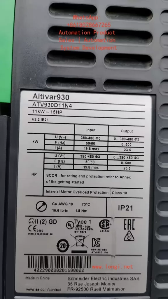
This guide is compiled based on the ATV900 Series Universal Programming Manual (NHA80762). For practical applications, verify parameter availability in conjunction with specific models and firmware versions. For complex application scenarios, it is recommended to use Schneider Electric’s SoMove configuration software for detailed debugging.