
1. Introduction
In modern industrial automation systems, the inverter is the core device for motor control and energy-saving operations. It is widely used in pumps, fans, compressors, and various mechanical transmission systems. Among them, the Yaskawa V1000 inverter has become a popular choice due to its compact design, high reliability, and stable performance.
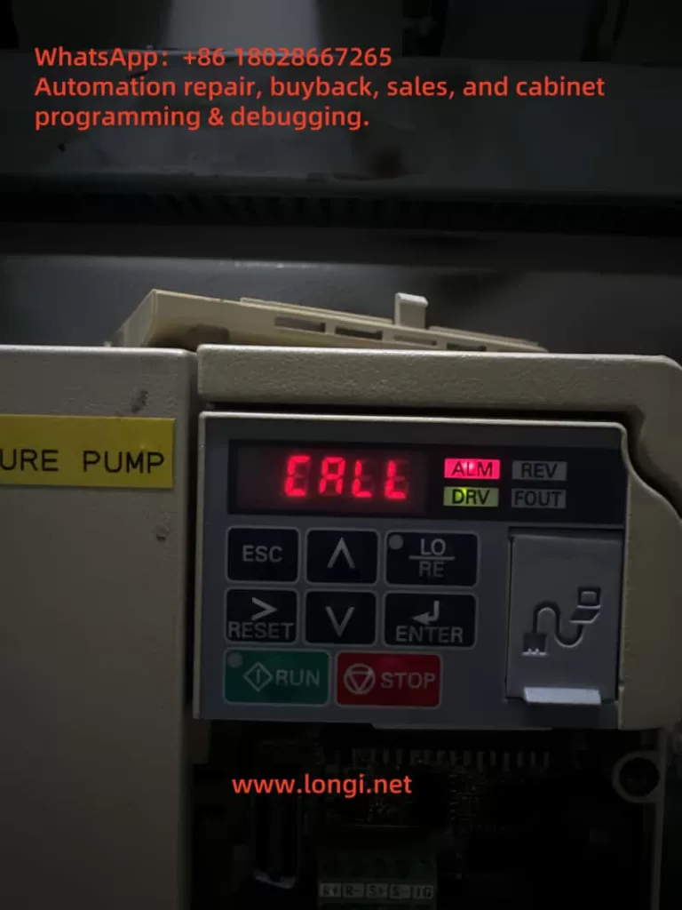
However, during field operation, many users encounter a situation where the inverter’s keypad displays “CALL”, while the ALM (alarm) indicator is lit. For beginners, this situation may seem confusing—“CALL” is often mistaken as a call instruction or program recall. In reality, it represents a communication-related warning.
This article will analyze the meaning of the CALL alarm, its possible causes, troubleshooting methods, and preventive measures, offering a structured guide to help engineers resolve this problem effectively.
2. Meaning of CALL Alarm
On Yaskawa V1000 inverters, CALL means “Communication Awaiting”.
- When the inverter is set to communication control mode, it continuously waits for data from the master device (PLC, PC, or communication module).
- If no valid data is received within a specific time, the inverter enters the CALL state.
- In this case, the ALM LED turns on, indicating a minor fault (warning). Unlike a trip fault, it does not immediately stop the inverter but signals that communication has not been established correctly.
Therefore, CALL is not a severe error code, but a reminder that the communication link is inactive or faulty.
3. Main Causes of CALL Alarm
Based on Yaskawa’s official manual and field experience, the CALL warning is generally triggered by the following issues:
1. Incorrect communication wiring
Improper connection of RS-485 or MECHATROLINK cables, short circuits, loose connections, or broken wires will cause communication failure.
2. Master device program not running or faulty
If the PLC or PC is not transmitting communication commands, the inverter will always remain in the CALL state.
3. Communication circuit malfunction
Damaged communication modules, defective ports, or strong external interference may disrupt data transmission.
4. Improper termination resistor setting
In Modbus/MEMOBUS or MECHATROLINK systems, termination resistors must be installed at both ends of the communication line. Incorrect settings lead to unstable signals and communication errors.
5. Incorrect control mode settings
If the inverter is configured to communication mode (e.g., o2- parameters set to serial communication) but no master is connected, it will always display CALL.
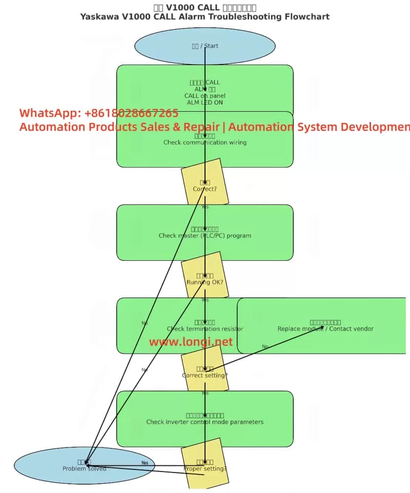
4. Troubleshooting Steps
When the inverter shows CALL with ALM lit, the following step-by-step procedure is recommended:
Step 1. Check wiring
- Verify RS-485 polarity (A/B terminals).
- Ensure shielded twisted pair cables are used and grounded properly.
- Inspect for loose, shorted, or broken wires.
Step 2. Check the master device
- Confirm that the PLC or PC communication port is enabled.
- Ensure that the master continuously transmits communication commands (e.g., Modbus function codes, MECHATROLINK frames).
- Debug the ladder program to confirm proper command output.
Step 3. Check termination resistors
- Install a 120Ω resistor at both ends of the communication line.
- If the V1000 has an internal switch for termination resistance (e.g., S2 switch), ensure it is set to ON.
Step 4. Verify inverter parameters
- Confirm o2- parameters (control mode selection).
- If communication is not required → set the mode to panel or terminal control.
- If communication is required → ensure correct baud rate, parity, and slave address settings.
Step 5. Power cycle test
- After corrections, restart the inverter.
- If CALL disappears, the issue is solved.
- If it persists, consider replacing the keypad, communication module, or contacting Yaskawa technical support.
5. Case Studies
Case 1: Wiring error
A water pump system using PLC + V1000 in communication control showed CALL constantly. Upon inspection, RS-485 polarity was reversed. Correcting the wiring resolved the issue immediately.
Case 2: Master program inactive
In a production line upgrade, V1000 inverters were linked by Modbus. Since the PLC program had not been downloaded yet, all inverters displayed CALL. Once the master program was activated, the alarms cleared.
Case 3: Termination resistor missing
In a long-distance bus network, multiple V1000 units showed CALL alarms. Investigation revealed no termination resistors were installed. Adding 120Ω resistors at both ends solved the communication problem.
6. Preventive Measures
To avoid recurring CALL alarms, engineers should adopt the following best practices:
- Standardized wiring
- Always use shielded twisted pair cables.
- Properly ground the shield layer to reduce interference.
- Reliable master program
- Ensure PLC/PC programs send communication frames immediately after startup.
- Include heartbeat signals to prevent timeouts.
- Correct termination resistor setup
- Always place resistors at both ends of the communication line.
- Verify onboard termination switch settings.
- Control mode configuration
- If communication is not required, set the inverter to terminal or panel control to prevent unnecessary CALL states.
- If communication is required, confirm all protocol settings match between master and slave devices.
- Regular maintenance
- Periodically inspect cable connections and terminal blocks.
- Check communication bus health in multi-inverter systems.
7. Conclusion
The CALL alarm on Yaskawa V1000 inverters is essentially a communication waiting warning, not a critical trip. It indicates that the inverter is not receiving valid data from the master device.
By systematically checking wiring, master device operation, termination resistors, and control parameters, engineers can quickly identify and resolve the issue. Moreover, if communication is not used, simply switching to panel or terminal control mode will prevent the CALL alarm.
Understanding CALL’s meaning and mastering troubleshooting procedures not only reduces downtime but also enhances the reliability of the overall automation system.