
1. Product Overview
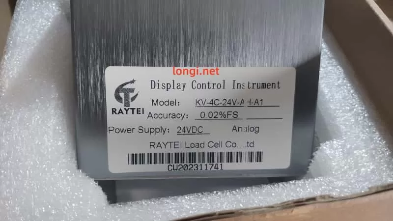
The KV-4C-24V-A-+A1 weighing display controller, developed by RAYTEI, is a high-precision signal display and control instrument designed for use with strain gauge load cells. It is ideal for monitoring and controlling forces such as tension, compression, weight, and pressure in industrial applications.
This controller features rich I/O capabilities, easy parameter configuration, dual-row LED real-time display, and analog/digital outputs. It integrates seamlessly into systems like packaging machines, injection molding, press machines, and testing equipment.
2. Features and Working Principle
2.1 Key Features
- High Precision: Accuracy up to ±0.02% FS, suitable for demanding industrial measurements.
- Dual Display Windows: Simultaneously shows current value and peak/valley/setting value.
- Multiple Units Supported: Supports unit switching between kg, g, N, and t.
- Multi-output: Includes 2 relay outputs (OUT1, OUT2), analog output (4–20mA, 0–10V, etc.).
- RS-485 Communication: Supports Modbus protocol for PLC or HMI communication.
- User-Friendly Panel: 5-key panel for quick access to settings, calibration, peak/valley, and zeroing.
- Strong EMC Protection: Industrial-grade electromagnetic compatibility, suitable for harsh environments.
2.2 Working Principle
The controller reads analog microvolt signals from a load cell through a strain bridge input. It performs high-resolution A/D conversion and computes the corresponding force value. The system displays real-time values and outputs control signals (digital or analog) based on user-defined parameters like thresholds, peaks, valleys, or calibration settings.
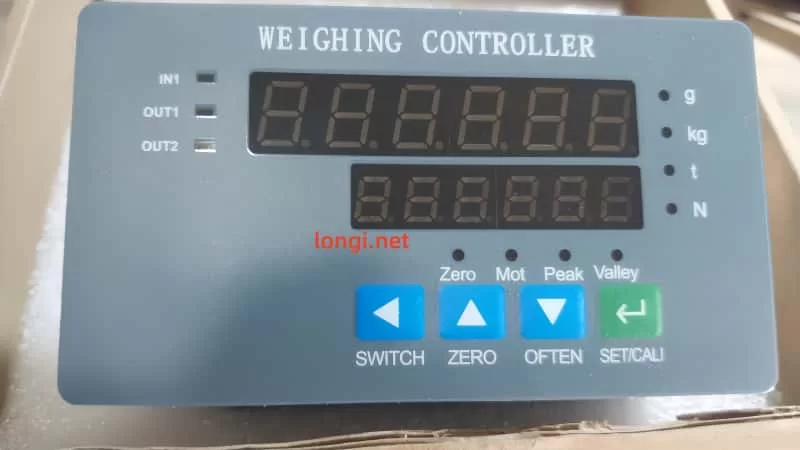
3. Front Panel and Basic Operation
3.1 Indicator Overview
- IN1: Input signal indicator (e.g., signal from load cell detected)
- OUT1 / OUT2: Relay output indicators
- Status LEDs:
- Zero – Zeroing active
- Mot – Motion state
- Peak / Valley – Peak and valley tracking indicators
3.2 Key Functions
| Button | Function Description |
|---|---|
SWITCH | Switch between display modes or menu pages |
ZERO | Tare (zero the current load) |
OFTEN | Common function key (save, view peaks, etc.) |
SET/CALI | Enter setup or calibration mode |
4. Operating Instructions
4.1 Basic Startup Procedure
- Power On → Device performs self-check and version display.
- Connect Load Cell → Wire sensor input to IN1, VCC, and GND terminals.
- Tare the Scale → Ensure no load is applied, press and hold
ZEROto reset to zero. - Set Capacity → Enter
SET/CALIto configure rated capacity and calibration points. - Set Thresholds → Define upper/lower limits for OUT1/OUT2 triggers.
- Output Test → Apply force/load to verify relay activation or analog output change.
- Save Settings → Press and hold
OFTENto store changes.
5. Calibration Methods
5.1 Quick Calibration (CAL1)
Used for simple field calibration:
- Remove load → Display reads 0.
- Press
SET/CALIto enter CAL1. - Confirm zero load point.
- Apply full load → Enter expected value.
- Confirm and exit.
5.2 Multi-Point Calibration (CAL3)
For non-linear sensors or high-accuracy demand:
- Supports up to 7 calibration points.
- Sequentially apply known loads and enter each value.
5.3 Analog Output Calibration (CAL4)
To match analog signal range (4–20mA / 0–10V) with actual force range:
- Requires digital multimeter to monitor output.
- Use
CAL4to adjust span and offset precisely.
6. Parameter Settings Overview
Use SWITCH to navigate between function pages (F1 to F9). Below are key groups:
| Group | Description |
|---|---|
| F1 | Sampling, filter, unit selection |
| F2 | Peak/valley hold settings |
| F3 | Upper/lower limit for relay outputs |
| F4–F6 | Analog output scaling and mode |
| F7 | RS-485 communication settings |
| F9 | Password protection, parameter lock |
Reminder: Always press OFTEN to save settings before exiting.
7. Maintenance Guidelines
7.1 Regular Calibration
- Calibrate every 6–12 months for optimal accuracy.
- Recalibrate if load cell or mounting configuration changes.
- If analog output drifts, recalibrate using CAL4.
7.2 Cleaning and Handling
- Clean panel surface with a dry soft cloth. Avoid solvents.
- Prevent moisture from entering connector ports.
- Periodically inspect terminal screws and wire condition.
7.3 Common Fault Diagnosis
| Error Code | Description |
|---|---|
| Err01 | Upper limit exceeded |
| Err02 | Lower limit exceeded |
| Err03 | No sensor signal |
| Err06 | RS-485 communication failed |
| Err09 | Power supply fault |
In case of errors, verify power, sensor wiring, configuration, and hardware status.
8. Technical Specifications
| Specification | Value |
|---|---|
| Power Supply | 24VDC |
| Power Consumption | ≤3W |
| Accuracy | ±0.02%FS |
| Input Type | Strain gauge (±20mV) |
| Output | Relay × 2, Analog, RS-485 |
| Panel Size | 107×44mm (cutout 92×44mm) |
| Mounting Type | Panel embedded |
| Operating Temp | -10℃ to +50℃ |
9. Summary
The KV-4C-24V-A-+A1 weighing controller is a robust, compact, and user-friendly industrial force display solution, featuring excellent accuracy and diverse I/O functionality. It is an ideal choice for automated production lines, force testing systems, press-fit machines, and similar applications.
For detailed Modbus register maps, calibration flowcharts, and electrical schematics, please refer to the official product manual provided by RAYTEI Load Cell Co., Ltd or consult their technical support team.