Posted on

Comprehensive Guide to Communication Parameter Settings of Yaskawa V1000 Inverter —— Accessing and Configuring H5-01 and H5-02

Introduction

In modern industrial automation, inverters (VFDs) are not only used for motor speed control but also serve as vital communication nodes between field devices and PLCs or supervisory systems. The Yaskawa V1000 series, as a compact vector control inverter, is widely applied in conveyors, fans, pumps, compressors, and other equipment due to its stable performance and rich features.
However, many engineers encounter a common issue during commissioning: Why can’t I find H5-01 or H5-02 communication parameters in the V1000 menu?

V1000

This article will provide a systematic explanation from the perspective of communication card hardware requirements, panel operation, step-by-step key procedures, and troubleshooting methods. After reading, you will fully understand how to access and correctly configure the H5 parameters on a V1000 inverter, enabling MEMOBUS (Modbus RTU) communication without confusion.


I. Communication Basics of the V1000 Inverter

1.1 Limitations of the Standard Model

The standard version of the V1000 does not include an RS-485 port by default. It only supports local operation through I/O terminals, such as start/stop signals and analog inputs. Therefore, if you search for H5-01 (slave address) or H5-02 (baud rate) in the parameter menu, you will not find the H5 parameter group.

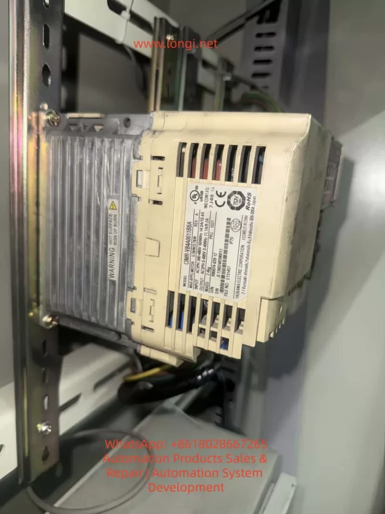
1.2 Necessity of Expansion Cards

To enable communication, dedicated option cards must be installed, such as:

  • SI-485: RS-485 (Modbus RTU) communication card
  • SI-232: RS-232 communication card
  • Other fieldbus option cards: Profibus-DP, DeviceNet, CANopen, CC-Link, etc.

Once installed, the inverter automatically activates the relevant parameter group and displays H5-01, H5-02, and other settings.

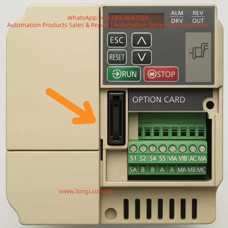
1.3 Installation Position of Expansion Cards

Above the control terminal block of the V1000, there is a long pin connector slot designed for option cards. Installation requires:

  1. Powering off and discharging the inverter to ensure safety.
  2. Removing the front cover to expose the slot.
  3. Inserting the communication card firmly into the slot and securing it with screws.
  4. Re-powering the inverter, which will then detect the card and load the H5 parameter group.

OPTION CARD

II. Operation Panel Types and Differences

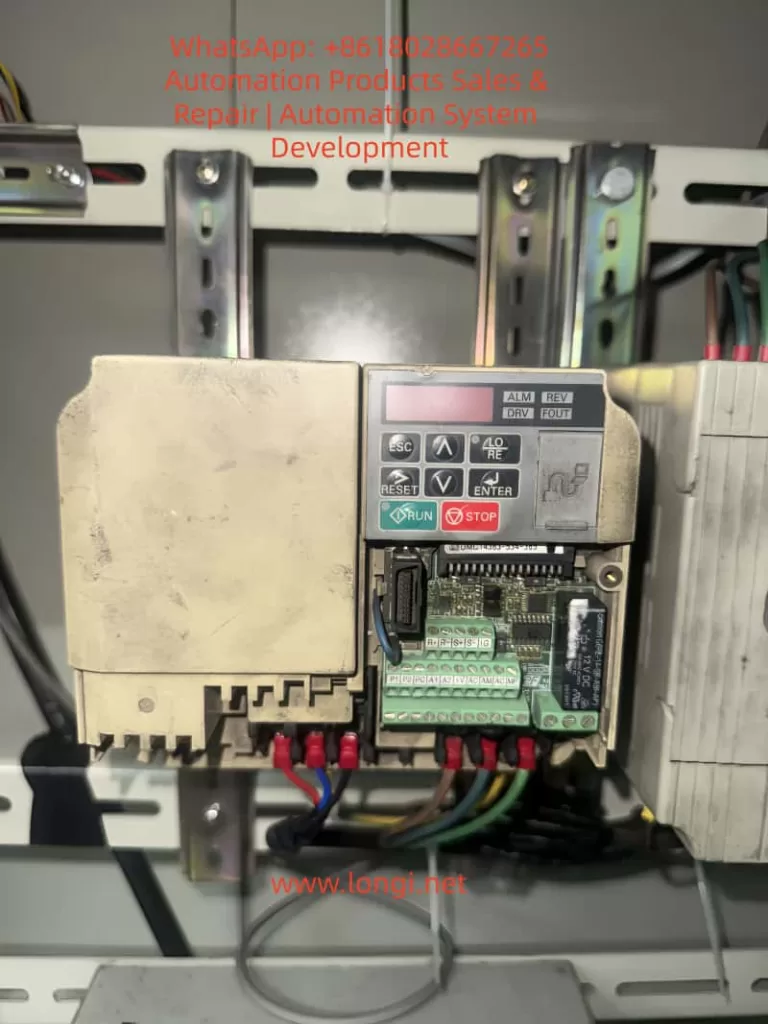
2.1 Standard LED Operator

Most V1000 units are equipped with a simplified LED operator panel, which includes the following buttons:

  • ESC (Exit/Back)
  • RESET (Fault reset)
  • ↑/↓ (Parameter navigation or value adjustment)
  • ENTER (Confirm/Save)
  • RUN/STOP (Start/Stop motor)

Unlike larger inverters, this panel does not have a dedicated PRG key. To enter the parameter menu, you need to press and hold ESC for about 2 seconds instead of pressing PRG.

2.2 Advanced LCD Operator (Optional)

Some models may be equipped with an LCD operator panel, which provides more advanced displays and shortcut keys. Regardless of the panel type, the process of accessing H5 parameters is the same, with only minor differences in button usage.


CIMR-VB4A0011BBA

III. Step-by-Step Procedure to Access H5 Parameters

The following example is based on the standard LED operator commonly found on the V1000.

Step 1: Enter Parameter Mode

  • After powering on, the display shows motor frequency, such as 0.00.
  • Press and hold the ESC key for 2 seconds to enter the parameter group selection mode.
  • The screen will display a parameter code, for example A1-01.

Step 2: Navigate to the H5 Parameter Group

  • Use the ↑/↓ keys to scroll through parameter groups.
  • You will see: A1-xxb1-xxC1-xx
  • Continue scrolling until you find H5-01.

⚠️ Note: If the communication card is not installed or not recognized, the H5 parameter group will not appear.

Step 3: Configure H5-01 (Slave Address)

  • When H5-01 is displayed, press ENTER.
  • The screen switches to the current value, for example 01.
  • Use ↑/↓ to set the slave address (range 0 to FFH).
  • Press ENTER to save.
  • The screen briefly flashes, then returns to H5-01.

Step 4: Configure H5-02 (Baud Rate)

  • Press ESC to return to the parameter list.
  • Scroll to H5-02.
  • Press ENTER to view the current value, e.g., 03 (9600bps).
  • Use ↑/↓ to select the desired baud rate:
    • 0 = 1200bps
    • 3 = 9600bps
    • 4 = 19200bps
    • 8 = 115200bps
  • Press ENTER to save.

Step 5: Return to Monitoring Mode

  • Press ESC repeatedly until the display returns to the main frequency screen (e.g., 0.00).
  • The parameters are now set.

IV. Common H5 Configuration Examples

4.1 Single-Inverter Communication

  • H5-01 = 01 (slave address = 1)
  • H5-02 = 4 (baud rate = 19200bps)
  • Configure the PLC master with address 01 and baud rate 19200bps for communication.

4.2 Multi-Inverter Communication

  • Several V1000 inverters connected on the same RS-485 bus.
  • Each inverter must have a unique H5-01 value, e.g., 01, 02, 03.
  • All devices must share the same H5-02 baud rate, e.g., 19200bps.
  • Ensure termination resistors are enabled on both ends of the bus.

4.3 Commissioning Notes

  • A power cycle is required after parameter changes for them to take effect.
  • If communication fails, check baud rate and slave address consistency, and confirm R+/R- wiring polarity.

V. Common Issues and Solutions

5.1 H5 Parameters Missing

Cause: Communication card not installed, or wrong card type.
Solution: Ensure SI-485 card is installed properly and compatible with V1000.

5.2 Parameter Changes Not Effective

Cause: Some parameters only apply after restart.
Solution: Power off and restart the inverter after changes.

5.3 Communication Interruption

Cause: Long cable runs or strong EMI interference.
Solution: Use shielded twisted pairs, ground the shield properly, and add termination resistors.

5.4 Panel Buttons Differ from Manual

Cause: Different operator versions (LED vs. LCD).
Solution: For LED panels, press and hold ESC; for LCD versions, PRG may be available.


VI. Conclusion

This article systematically explained how to access and configure H5-01 and H5-02 parameters on the Yaskawa V1000 inverter. From hardware requirements (communication card installation) to operator panel differences and detailed step-by-step key operations, all potential problems have been clarified.

In short:

  1. H5 parameters will not appear without a communication card.
  2. On LED operators, hold ESC to enter parameter mode.
  3. Always save changes and restart for them to take effect.

By mastering these procedures, engineers can easily configure V1000 inverters for Modbus RTU communication, ensuring seamless integration into automation systems.

Posted on

Practical Guide to ABB EL3020 Gas Analyzer: Negative CO Readings and Zero/Span Calibration

1. Introduction

In industrial emission monitoring, combustion control, and process analysis, gas analyzers play a critical role in ensuring safety, efficiency, and compliance with environmental standards. The ABB EL3020 is a widely used multi-component gas analyzer based on infrared optical measurement principles. It is designed to continuously monitor gases such as CO, CO₂, NO, and SO₂ in various industrial applications.

However, during long-term operation, users may sometimes encounter abnormal readings, the most common of which is negative CO concentration values. Such readings do not imply the physical existence of “negative carbon monoxide,” but instead reflect calibration drift, background interference, or hardware-related issues.

This article provides a detailed explanation of the EL3020’s measurement principle, analyzes the possible causes of negative CO readings, and presents practical zero calibration and span calibration procedures. The aim is to help engineers and operators quickly identify the root cause, restore measurement accuracy, and ensure stable operation of the analyzer.


EL3120

2. Operating Principle of ABB EL3020

2.1 Infrared Absorption Principle

The EL3020 operates on the principle of non-dispersive infrared absorption (NDIR).

  • Each gas molecule has a unique absorption band in the infrared spectrum.
  • When an infrared beam passes through a sample gas containing CO, the CO molecules absorb energy at specific wavelengths.
  • The detector measures the reduction in light intensity, which is directly proportional to the gas concentration.
  • By comparing the reference and measurement channels, the analyzer calculates the gas concentration.

2.2 Zero and Span Definitions

  • Zero Point: The output signal when no target gas is present (pure zero gas condition). Ideally, the instrument should display 0 ppm.
  • Span Point: The output when a known concentration of calibration gas is introduced. Span calibration adjusts the slope factor to ensure linear accuracy.

CO shows a negative value

3. Causes of Negative CO Readings

3.1 Zero Drift

Over time, detector electronics and optical components may drift due to temperature variations and aging. If the zero point is not recalibrated, the baseline may shift below zero, producing negative values.

3.2 Background Interference

If the sampled gas contains almost no CO while the instrument’s baseline is incorrectly set too high, the computed result may fall below zero. Excess oxygen, water vapor, or other gases can also disturb the optical path.

3.3 Optical Contamination or Aging

Dust, condensation, or weakened infrared sources reduce the signal strength at the detector, leading to baseline shifts.

3.4 Hardware or Circuit Faults

Faults in the analog acquisition board, A/D converters, or signal amplifiers can also cause abnormal negative readings. If only the CO channel is affected while NO and O₂ are stable, the issue likely lies in the CO detection unit.


4. Zero Calibration Procedure

Zero calibration eliminates baseline drift and resets the analyzer output to zero under clean gas conditions.

4.1 Preparation

  1. Use high-purity nitrogen (99.999%) or certified zero air as the zero gas.
  2. Verify gas purity and set regulator output pressure to ~2 bar.
  3. Check sample lines for leakage or condensation.
  4. Power on the analyzer for at least 30 minutes to stabilize.

4.2 Step-by-Step Process

  1. On the panel, navigate: OK → Menu → Calibration → Zero Calibration.
  2. Select the CO channel.
  3. Switch the sample inlet to zero gas and flush for 3–5 minutes until stable.
  4. Execute Start Zero Calibration.
  5. After completion, the CO value should display close to 0 ppm (±2 ppm acceptable).

4.3 Evaluation

  • If “Zero OK” appears and the reading stabilizes, calibration is successful.
  • If negative values persist, further action such as span calibration or hardware inspection may be required.

5. Span Calibration Procedure

Span calibration corrects the proportionality factor (slope) to align measured values with certified standard gas concentrations.

5.1 Preparation

  1. Use certified CO span gas, preferably at 60–90% of the measurement range (e.g., 100 ppm CO in N₂).
  2. Check cylinder, pressure regulator, and tubing for leaks.
  3. Perform zero calibration before span calibration for best results.

5.2 Step-by-Step Process

  1. On the panel, navigate: OK → Menu → Calibration → Span Calibration.
  2. Select the CO channel.
  3. Switch the sample inlet to the standard gas and flush for 5–10 minutes until stable.
  4. Enter the certified gas concentration (e.g., 100 ppm).
  5. Execute Start Span Calibration.
  6. The analyzer adjusts the slope factor and confirms with Span OK.

5.3 Evaluation

  • If the analyzer output matches the certified value (within ±2%), span calibration is successful.
  • Large deviations indicate optical degradation or electronic faults that may require service intervention.

6. Maintenance and Troubleshooting Recommendations

  1. Regular Calibration
    • Perform zero calibration monthly and span calibration every 1–3 months.
  2. Optical Cleaning
    • Inspect and clean optical windows and gas cells regularly. Prevent dust and moisture accumulation.
  3. Sample Line Maintenance
    • Avoid condensation and leaks in tubing. Use filters and dryers where necessary.
  4. Validation with Reference Gas
    • Periodically validate with independent standard gas to ensure accuracy.
  5. Hardware Inspection
    • If calibration fails, check the infrared source, detectors, and analog boards. Replace if necessary.

7. Case Study: Negative CO Reading Restored by Calibration

In a steel plant, operators observed the EL3020 CO channel consistently showing -5 ppm.

  1. Zero calibration with nitrogen reduced the offset, but the value remained at -3 ppm.
  2. A span calibration using 100 ppm CO gas showed the analyzer reading 95 ppm.
  3. After span adjustment, the zero point stabilized near 0 ppm and span response matched 100 ppm.

The issue was traced to slope drift in the CO channel, which was successfully corrected through calibration without requiring hardware replacement.


8. Conclusion

The ABB EL3020 is a reliable and accurate gas analyzer for continuous industrial monitoring. Negative CO readings are typically not measurement of “negative concentration” but symptoms of baseline drift or span factor deviation. Proper and regular zero calibration and span calibration are essential to maintain measurement accuracy.

For persistent negative values that cannot be corrected through calibration, optical contamination, component aging, or hardware malfunction should be considered. Timely maintenance and service support are key to ensuring the long-term stability of the analyzer.

By following standardized calibration procedures and maintenance practices, operators can keep the EL3020 functioning accurately and extend its service life in demanding industrial environments.


Posted on

Hach Amtax SC Ammonia Nitrogen Analyzer User Guide

I. Instrument Principle and Features

The Hach Amtax SC Ammonia Nitrogen Analyzer is an online analytical device specifically designed for continuous monitoring of ammonium ion concentration in water bodies. It is widely used in wastewater treatment plants, waterworks, surface water monitoring, and industrial process control. Its core measurement principle is the Gas Sensitive Electrode (GSE) method, where a selective electrode reacts with ammonium ions in the sample, and the concentration value is ultimately output in the form of NH₄–N on the controller (sc1000).

Key Technical Features:

  • Wide Measurement Range: Covers three intervals: 0.05–20 mg/L, 1–100 mg/L, and 10–1000 mg/L, allowing flexible application in both low-concentration surface water and high-concentration wastewater scenarios.
  • Fast Response: 90% response time of less than 5 minutes, suitable for real-time monitoring of dynamic water quality.
  • High Precision and Reproducibility: Measurement error is less than ±3% or ±0.05 mg/L (for low ranges), ensuring reliable data.
  • Automation Capabilities: Features automatic calibration, automatic cleaning, and diagnostic functions, significantly reducing manual intervention.
  • Robust Design: Enclosure with an IP55 protection rating and made of UV-resistant ASA/PC material, suitable for harsh outdoor environments.
  • Modular Expandability: Enables data transmission and remote monitoring through the sc1000 controller, supporting single-channel or dual-channel modes.
    Thus, the Amtax SC combines high precision, low maintenance, and strong adaptability, making it a mainstream choice in the field of ammonia nitrogen online monitoring.

II. Installation and Calibration

1. Mechanical Installation

  • Mounting Options: Supports wall mounting, rail mounting, or vertical installation, with wall mounting being the most common. Choose a sturdy, load-bearing wall and ensure smooth routing of surrounding pipes and cables.
  • Weight and Load Requirements: The instrument weighs approximately 31 kg, and the bracket must support a load of ≥160 kg.
  • Installation Environment: Avoid strong vibrations, strong magnetic fields, and direct sunlight. Maintain an ambient temperature range of –20 to 45°C.

2. Electrical Installation

  • Must be performed by qualified personnel to ensure proper grounding and the installation of a residual current device (30 mA RCD).
  • Power is supplied by the sc1000 controller, with voltages of 115V or 230V. The use of 24V controller models is prohibited.
  • All piping and reagent installations must be completed before powering on.

3. Reagent and Electrode Installation

  • Reagent Preparation: Select standard solutions and reagents according to the measurement range. For example, use 1 mg/L and 10 mg/L standard solutions for low ranges, and 50 mg/L and 500 mg/L for high ranges.
  • Electrode Installation: Fill with electrolyte (approximately 11 mL), ensuring no air bubbles remain, and correctly insert the electrode into the electrolysis cell. Replace the membrane cap and electrolyte every 2–3 months.
  • Humidity Sensor: Must be correctly wired to prevent alarms triggered by condensation or liquid leakage.

4. Calibration Procedure

  • Calibration modes include automatic calibration and manually triggered calibration.
  • Set the calibration interval (typically once per day or shorter), and the system will automatically switch standard solutions for electrode correction.
  • After calibration, the system records key parameters such as slope, zero point, and standard solution potential to ensure long-term stable operation.

III. Startup and Operation

1. Startup Steps

  • Ensure all installations (piping, electrical, reagents, electrodes) are complete.
  • Connect the analyzer to the sc1000 controller and power on.
  • Initialize the system: Register the Amtax SC and sampling probe in the controller, execute the “Prepump All” function to fill the piping.
  • Allow a warm-up time of approximately 1 hour for the instrument, reagents, and electrodes to reach operating temperature.
  • Enter the sensor setup menu to confirm the measurement range, output units (mg/L or ppm), and measurement interval.

2. Normal Operation

  • LED Indicators: Green indicates normal operation, orange indicates a warning, and red indicates an error.
  • Measurement Interval: Adjustable from 5 to 120 minutes, depending on application requirements.
  • Data Viewing: The sc1000 controller displays real-time values, historical trends, and alarm status, and can upload data to a monitoring system via a bus interface.
  • Cleaning Function: Set up timed automatic cleaning to ensure the photometer, piping, and electrodes remain clean.

IV. Troubleshooting and Maintenance

1. Routine Maintenance

  • Appearance Inspection: Regularly check for damage to pipes and cables, and confirm the absence of leaks or corrosion.
  • Fan Filter: Clean or replace every 6–12 months to ensure proper heat dissipation.
  • Reagents and Electrodes: Replace reagents every 2–3 months, electrode membrane caps and electrolyte every 2–3 months, and electrodes every 1–2 years, as recommended in Table 5.
  • Cleaning Cycle: Depends on water hardness; typically perform automatic cleaning every 1–8 hours.

2. Common Faults and Solutions

  • Low/High Temperature: If the internal temperature falls below 4°C or rises above 57°C, the system enters service mode. Check the heating or cooling fan.
  • Humidity Alarm: Liquid detected in the collection tray; locate and repair the leak source.
  • Abnormal Electrode Slope: Check the membrane and electrolyte, replace the standard solution; if the issue persists, replace the electrode.
  • Weak Photometer Signal: Trigger cleaning; if unresolved, manually clean or contact a service technician.

3. Long-Term Shutdown and Storage

  • Flush the instrument with distilled water in a circulation mode to empty the pipes and reagent bottles.
  • Remove the electrode, clean it, and reinstall it in the electrolysis cell, keeping it moist during storage.
  • Install transport locks and store in a dry, frost-free environment.

4. Professional Repairs

  • Certain components (such as pumps, compressors, and main circuit boards) must be replaced by the manufacturer or authorized service personnel. Typical service lives: pumps 1–2 years, compressors 2 years, all covered under warranty.

V. Conclusion

The Hach Amtax SC Ammonia Nitrogen Analyzer is a stable and highly automated online monitoring device. It features a scientific principle, clear installation requirements, a straightforward operation process, and comprehensive maintenance methods. By strictly adhering to the user manual and this guide, users can ensure the long-term stable operation of the device, providing reliable data support for water quality monitoring and wastewater treatment process control. Correct installation, regular calibration, and maintenance are key to ensuring the instrument’s long-term stable operation. Users should strictly follow the safety specifications in the operation manual, regularly replace reagents and electrodes, and promptly address fault alarms to ensure measurement accuracy and extend the instrument’s service life.