
Introduction
In modern industrial automation systems, inverters serve as the core equipment for motor control, and their reliability and safety directly impact production efficiency and equipment lifespan. The Vacon NXP series inverters, produced by Danfoss, are renowned for their high performance, modular design, and advanced safety features. Among these features, the Safe Torque Off (STO) function is a critical safety characteristic of the series, designed to rapidly cut off motor torque output in emergency situations to prevent accidental movement that could cause injury or equipment damage. However, in practical applications, STO-related faults such as F30 (Safe Torque Off activated) and F8 S1 (system fault, sub-code S1, indicating device change) frequently occur, posing challenges for maintenance personnel.
This article, based on the Vacon NXP user manual, OPTAF option board manual, and practical diagnostic experience, provides a comprehensive exploration of the principles of the STO function, common fault analysis, diagnostic methods, solution steps, configuration optimization, and testing and maintenance strategies. The article aims to offer practical guidance to engineers and technicians, helping them quickly troubleshoot faults and optimize system configurations. Through detailed step-by-step instructions and logical analysis, we will uncover the root causes of these faults and propose preventive measures. By incorporating online resources and case studies, this article ensures the originality and practicality of its content.
The Vacon NXP series is suitable for use in manufacturing, shipping, mining, and other fields, supporting power ranges from 0.75 kW to several megawatts. Its STO function complies with EN 61800-5-2 and IEC 61508 standards, achieving a SIL3 safety integrity level. Understanding these faults not only reduces downtime but also enhances overall system safety. Next, we delve into the basic principles of STO.
Detailed Explanation of STO Function Principles
Safe Torque Off (STO) is a hardware-level safety function designed to prevent the motor from generating torque by interrupting the inverter’s pulse-width modulation (PWM) signals, independent of software control. This ensures rapid response in the event of a fault or emergency, typically completed within 20 milliseconds. In Vacon NXP inverters, STO is implemented through the OPTAF option board, which is installed in slot B of the control board and provides isolated STO input channels.
The terminal layout of the OPTAF board includes:
- Terminal 1: SD1+ (Channel 1 positive, logic 1 when connected to +24V)
- Terminal 2: SD1- (Channel 1 negative, connected to GND)
- Terminal 3: SD2+ (Channel 2 positive, logic 1 when connected to +24V)
- Terminal 4: SD2- (Channel 2 negative, connected to GND)
Both channels must be simultaneously closed (logic 1) to enable the drive. If the channel states differ for more than 5 seconds or if either channel opens, STO is activated, causing the drive to stop outputting. This dual-channel redundancy design complies with Category 3 safety architecture, offering a diagnostic coverage rate of up to 99%.
The activation mechanism of STO includes control by an external safety switch S1. The manual describes various S1 wiring configurations:
- Basic configuration: S1 serves as a normally closed switch, directly connecting all four terminals to provide a simple emergency stop.
- Configuration with reset: A reset button is added, connected to a digital input, allowing fault confirmation and subsequent recovery.
- Configuration with time delay: A safety relay (such as Pilz PNOZ) is integrated to first execute a ramp-down (Safe Stop 1, SS1) before activating STO.
Additionally, the OPTAF board supports ATEX thermistor inputs (TI1+ and TI1-) for motor over-temperature protection in explosive environments. Jumper X12 must be disconnected to enable this function; otherwise, other faults may be triggered.
In principle, STO does not provide electrical isolation but only prevents torque; complete safety requires a combination with a main disconnect switch. Parameter P2.12.1.6 (ID755) controls the response mode: 0 (no response), 1 (warning A30), 2 (fault F30). The default setting is 1, ensuring safety while allowing automatic recovery.
Understanding these principles aids in fault diagnosis. For example, if the STO inputs are not shorted, F30 will frequently occur; after shorting, if the system detects a configuration change, F8 S1 may be triggered. Next, we analyze common faults.
Common Fault Analysis
STO-related faults in Vacon NXP inverters primarily include F30 and F8 S1. These faults do not occur randomly but are caused by hardware, configuration, or operational issues.
F30 Fault Analysis
F30 indicates Safe Torque Off activation, usually accompanied by sub-code 30, meaning the SD1 and SD2 channel states have been inconsistent for more than 5 seconds. Reasons include:
- External safety circuit opened: Such as when the S1 switch is pressed or a cable is disconnected.
- Incorrect input connection: If STO is not used but not shorted, it will continuously trigger.
- Hardware issues: OPTAF board failure, short circuit, or unstable power supply.
- Test pulse interference: Diagnostic pulses sent by external safety devices exceed the filtering threshold (dark pulse <3ms).
Under zero load conditions, F30 may appear as a warning A30 without recording a fault but still stopping output. The manual emphasizes that regardless of the mode, torque is immediately removed upon STO activation, with a response time of <20ms and a recovery time of <1000ms.
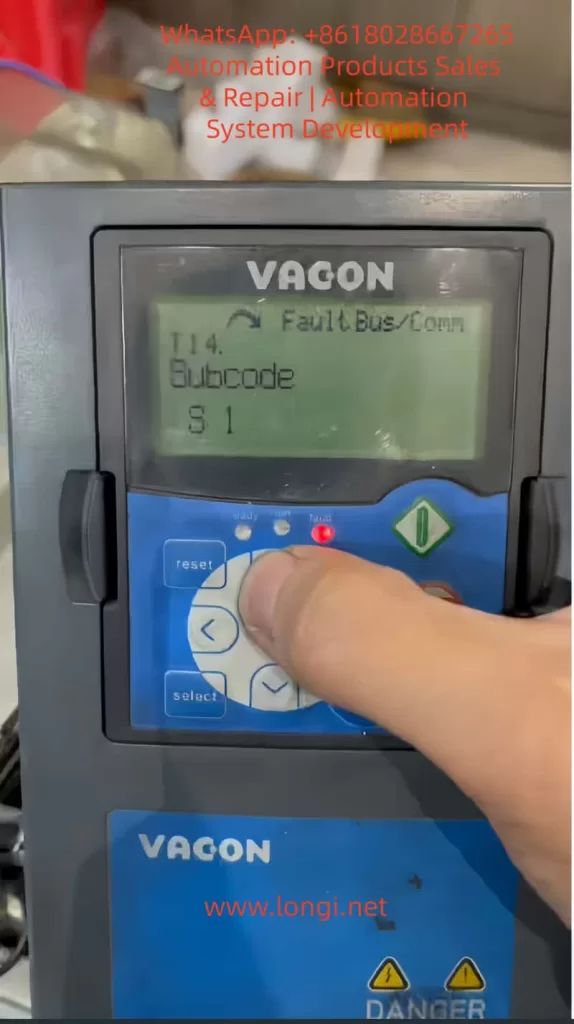
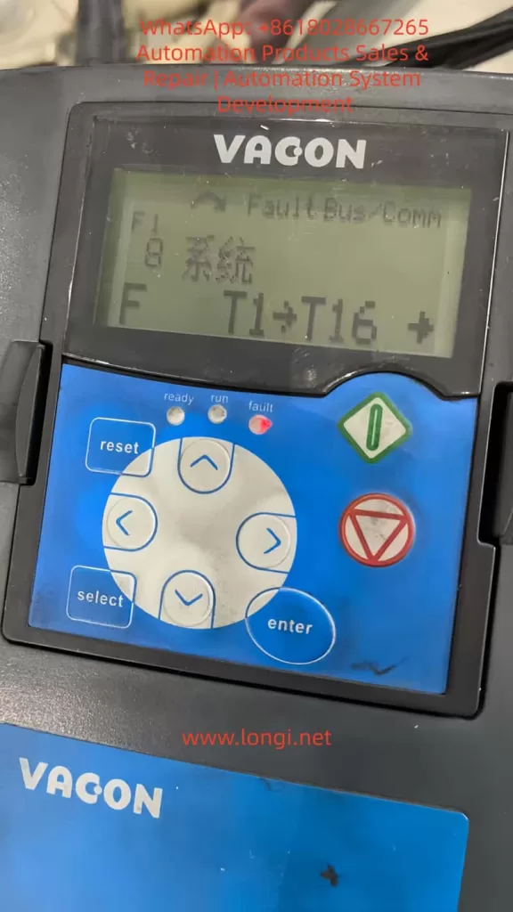
F8 S1 Fault Analysis
F8 is a system fault, with sub-code S1 specifically indicating “Device changed (same type),” meaning an option board (such as OPTAF) of the same type has undergone a change. This often occurs after shorting the STO inputs because the drive detects a change in input state from dynamic to static during hardware scanning, interpreting it as a configuration modification. Other sub-codes such as S8 (no power to the drive card) or S10 (communication interruption) may be related, but your case’s T values (T10-T13=0/1) point to S1.
Trigger mechanism: During drive startup self-check, the current hardware is compared with the last recorded configuration. If shorting changes the electrical characteristics or if the board experiences a brief power outage, S1 is activated. This is a safety verification, not a damage signal. Although S1 is listed as “Reserved” in the manual, it actually corresponds to device changes. It is unrelated to voltage feedback anomalies, which typically occur under load and correspond to different codes.
Other F8 sub-codes:
- S7: Charging switch fault – Check the DC bus.
- S9/S10: Communication interruption – Fiber optic issues.
- S48: Thermistor parameter mismatch – X12 jumper error.
The logical relationship between these faults: Fixing F30 (shorting) may induce S1 because change detection takes precedence over operational verification.
Detailed Diagnostic Methods
Accurate diagnosis is crucial for resolving faults. Use the keypad menu and tools for systematic checks.
Keypad Diagnostic Steps
- View active faults: Scroll to M4 (Active faults) to display F8 S1 Slot B.
- Check fault time data: Enter T.1-T.16 and record values (e.g., T14=S1, T16=Slot B).
- Monitor inputs: M1.23 DigIN to confirm B.2/B.3=1 (STO closed).
- Expand board status: M7 Slot B displays “Changed” to indicate S1.
Hardware Diagnostics
- Use a multimeter to measure STO terminal voltages (+24V/GND).
- Check fiber optic connections for dust.
- The manual recommends using an oscilloscope to verify pulse filtering.
Software Diagnostics
- Connect via NCDrive software, download parameter files, and compare changes.
- Check the firmware version (M6 S6.1) for OPTAF support.
Diagnostic logic: First, eliminate hardware issues (cables, power supply), then check configurations (parameters), and finally, perform a reset.
Detailed Solution Steps
Provide step-by-step guides for addressing F30 and F8 S1.
Solving F30
- Confirm the cause: Check the S1 switch and cables.
- Short-circuit bypass: Connect terminal 1/3 to +24V and terminal 2/4 to GND.
- Parameter adjustment: Set P2.12.1.6=0.
- Reset: Press the Reset button.
Solving F8 S1
- Simple reset: Press the Reset button or perform a power cycle restart.
- Factory restore: M6 S6.5 Restore defaults and reset motor parameters.
- Verify shorting: Ensure no short circuits exist.
- Test: Run at low speed while monitoring.
If ineffective, replace the OPTAF board.
Configuration Optimization Guide
Optimize STO configurations to enhance system performance.
Parameter Configuration
- P2.12.1.6: Set to 1 (warning) to balance safety and availability.
- P7.2.1.2: Set to Warning to allow automatic recovery.
- Integrate SS1: Set G2.3 deceleration time > delay.
Advanced Wiring
- Use a safety relay to implement SS1. The manual provides detailed examples.
Testing and Maintenance
- Regular testing: Activate STO to verify a <20ms response.
- Maintenance: Clean the board and check connections monthly.
Case Studies
- Case 1: A factory experienced F30; shorting led to S1, which was resolved by resetting.
- Case 2: Communication interruption S10 was resolved by replacing the fiber optic cable.
Conclusion
Through the guidance provided in this article, users can confidently handle STO faults. In the future, stay vigilant for firmware updates.