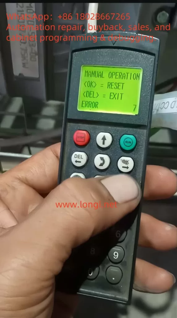
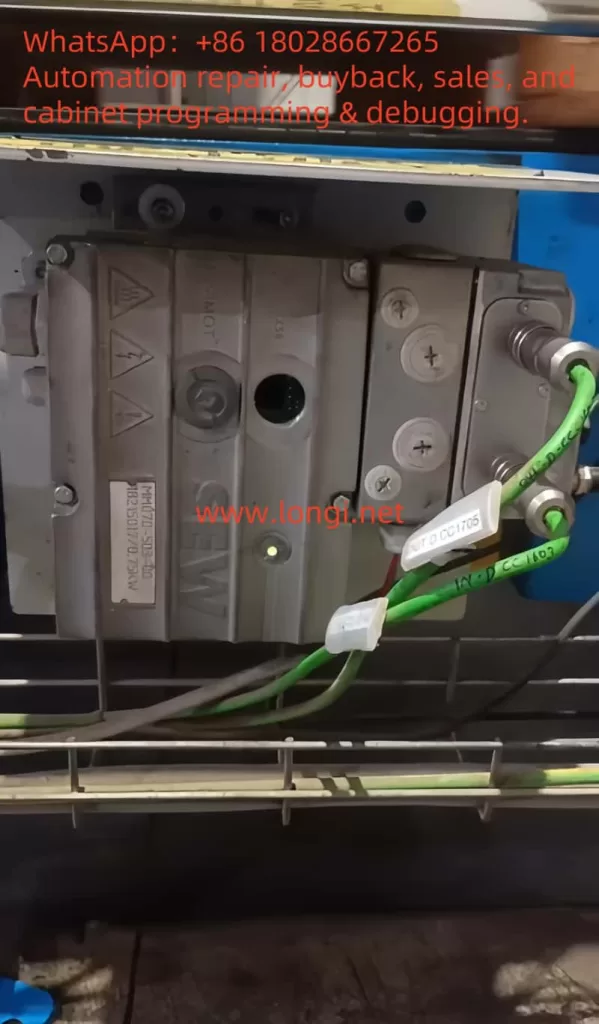
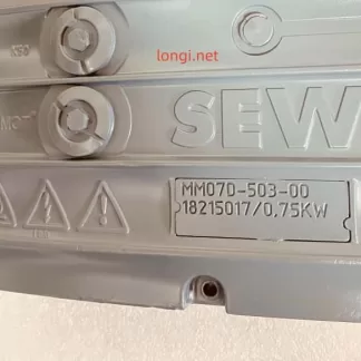
1. Meaning of ERROR 07 Fault Code
When the SEW-EURODRIVE MOVIMOT MM D series servo drive displays “ERROR 07,” it indicates “DC link voltage too high.” This fault typically occurs when the DC link voltage exceeds its rated range. According to the manual, the appearance of ERROR 07 can be caused by several factors, including short ramp times, faulty connections between the braking resistor and brake coil, incorrect internal resistance of the brake coil or braking resistor, thermal overload of the braking resistor, and invalid input voltage.

1.1 Ramp Time Too Short
If the ramp time is set too short, the voltage in the DC link can rise too quickly, triggering the ERROR 07 fault. The ramp time controls the speed at which the drive accelerates. If the ramp time is too short, it can cause excessive current and voltage variations, leading to this fault.
1.2 Faulty Connection Between Brake Coil and Braking Resistor
The braking resistor and brake coil are crucial for controlling the DC link voltage during braking. If there is a poor connection between the brake coil and braking resistor, energy from braking cannot be absorbed effectively, causing the DC link voltage to rise too high and triggering ERROR 07.
1.3 Incorrect Internal Resistance of Brake Coil/Braking Resistor
The internal resistance of the brake coil or braking resistor must be within specific limits to effectively control braking energy. If the resistance deviates from the required value, the braking system will not function properly, and the DC link voltage may increase, causing ERROR 07.
1.4 Thermal Overload of the Braking Resistor
If the braking resistor is undersized or overloaded, it can overheat, leading to excessive DC link voltage. In such cases, the braking resistor must be properly sized to withstand the required braking torque and power without overheating.
1.5 Invalid Voltage Range of Supply Input Voltage
The input voltage to the drive must remain within its specified range. If the input voltage exceeds this range, it can lead to an excessively high DC link voltage. It is essential to verify that the supply voltage is within the permissible range as specified by the drive.
2. Solutions
Depending on the root cause of the ERROR 07 fault, here are the detailed diagnostic steps and solutions:
2.1 Extend the Ramp Time
If the ramp time is too short, you can extend it to allow the voltage to rise more gradually. Increasing the ramp time helps prevent the voltage from increasing too quickly, which could trigger the fault.
Steps:
- Enter the drive’s configuration menu.
- Find the ramp time parameter (typically labeled as “Ramp Time”).
- Increase the ramp time to a value that allows the voltage to rise at a safe rate.
- Save the settings and restart the drive to check if the fault is resolved.
2.2 Check the Connection Between the Brake Coil and Braking Resistor
If the connection between the braking resistor and brake coil is faulty, check all connection points to ensure they are secure and not loose or disconnected. If there is a problem, repair or replace the connection.
Steps:
- Turn off the drive and disconnect the power.
- Inspect the connections between the brake coil and braking resistor for any loose or broken connections.
- Reconnect any faulty connections to ensure they are secure.
- Power on the drive and test if the fault is cleared.
2.3 Check and Adjust the Internal Resistance of the Brake Coil/Braking Resistor
The internal resistance of the brake coil and braking resistor should match the required specifications. Use a multimeter to measure the resistance and compare it with the specifications in the drive’s technical manual.
Steps:
- Use a multimeter to measure the resistance of the brake coil or braking resistor.
- Compare the measured resistance with the recommended value in the technical data section of the manual.
- If the resistance is incorrect, replace the brake coil or braking resistor with a new one that meets the specifications.
2.4 Properly Size the Braking Resistor
If the braking resistor is overloaded or improperly sized, it can cause thermal overload and lead to ERROR 07. The braking resistor should be able to absorb the energy produced during braking without overheating. Replace the braking resistor with one of the correct size.
Steps:
- Calculate the required power and torque for the braking resistor based on the drive’s load.
- Choose a braking resistor with sufficient power rating to handle the braking energy without overheating.
- Install the appropriately sized braking resistor and test the drive to confirm the fault is resolved.
2.5 Check the Input Voltage
If the input voltage exceeds the rated range of the drive, it may cause an excessive DC link voltage. Use a multimeter to check that the supply voltage is within the allowable range. If the voltage is too high, consider adjusting the power supply or replacing it with one that provides the correct voltage.
Steps:
- Use a multimeter to measure the input voltage to the drive.
- Ensure the voltage is within the rated range specified for the drive (typically 380V to 500V AC).
- If the input voltage is too high, check the power supply and adjust or replace it as necessary.

3. Preventive Measures to Avoid ERROR 07
To prevent ERROR 07 from recurring, the following measures can be taken:
3.1 Regularly Check and Maintain the Braking System
Regularly inspect the braking resistor and brake coil for proper connections and resistance values. Ensure that they meet the required specifications to avoid issues with braking performance.
3.2 Optimize Cooling and Ventilation
Ensure the drive is installed in a well-ventilated area to prevent overheating. Regularly clean the drive’s cooling fins and ensure there are no obstructions blocking airflow. Keeping the drive cool will help avoid thermal overload issues.
3.3 Properly Size the Braking Resistor
Always select the correct size of braking resistor based on the load requirements. Ensure the braking resistor can handle the required braking torque and power without overheating.
3.4 Monitor Input Voltage Stability
Monitor the input voltage to ensure it remains within the permissible range. Using a stable power supply that provides consistent voltage within the rated range will help prevent issues with the DC link voltage.
4. Conclusion
The SEW MOVIMOT MM D series servo drive is an essential component in modern automation systems. The ERROR 07 fault, which occurs due to high DC link voltage, can be caused by several factors such as short ramp times, faulty braking system connections, incorrect internal resistance, thermal overload of the braking resistor, or invalid input voltage. By following the diagnostic steps and solutions outlined above, you can effectively address and resolve this issue. Regular maintenance, proper configuration, and careful monitoring of the drive’s operation will ensure long-term reliability and optimal performance.

