
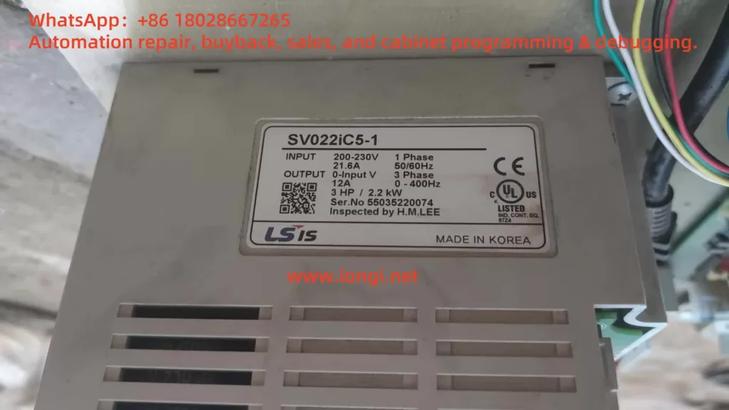
The LG (now LS) iC5 series inverter is a versatile and reliable variable frequency drive designed for precise motor control in various industrial applications. This guide provides a comprehensive overview of using the iC5 series inverter, focusing on the operation panel functions, parameter initialization, parameter access restrictions, password management, external terminal control for forward/reverse operation, external potentiometer frequency control, and fault code troubleshooting. This article aims to help users effectively operate and maintain the iC5 inverter based on the provided manual.
1. Operation Panel Functions and Parameter Management
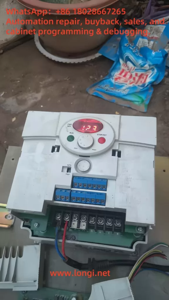
Operation Panel Overview
The operation panel of the LG iC5 series inverter is a critical interface for configuring and monitoring the device. It features a 7-segment LED display, status LEDs, and multiple keys for navigation and control:
- LED Display and Indicators:
- FWD LED: Illuminates during forward operation and flashes when a fault occurs.
- REV LED: Illuminates during reverse operation.
- 7-Segment LED Display: Shows operational status, parameter codes, and values.
- Keys:
- Run Key: Initiates inverter operation.
- Stop/Reset Key: Stops the inverter or resets faults.
- Four-Directional Keys (Up/Down/Left/Right): Used for navigating parameter groups, selecting codes, or adjusting values.
- Prog/Ent Key: Confirms parameter settings or saves changes.
- Potentiometer: Adjusts the running frequency manually.
The panel organizes parameters into four groups: Drive Group (basic parameters like target frequency and acceleration/deceleration times), Function Group 1 (basic frequency and voltage adjustments), Function Group 2 (advanced features like PID control), and I/O Group (input/output terminal settings).
Parameter Initialization
Parameter initialization resets all parameters to factory defaults, which is useful when troubleshooting or reconfiguring the inverter. To initialize parameters in the Function Group 2 at parameter H93:
- Navigate to H0: Access Function Group 2 by pressing the Right key repeatedly until “H 0” is displayed.
- Enter H93: Press the Prog/Ent key, then use the Up key to set the code to “93” (adjust digits with Left/Right keys as needed). Confirm with Prog/Ent.
- Set Initialization: The default value is “0”. Use the Up key to change it to “1” to enable initialization, then press Prog/Ent. The display will flash, indicating completion.
- Return to H0: Press Left or Right to return to the first code of Function Group 2.
Note: After initialization, all parameters revert to factory settings, requiring re-configuration for specific applications.
Parameter Access Restrictions and Password Management
To prevent unauthorized changes, the iC5 series allows setting parameter access restrictions and passwords:
- Setting Parameter Access Restrictions:
- In Function Group 2, navigate to H94 (Parameter Lock).
- Press Prog/Ent, set a value (e.g., “1” for lock), and confirm. This restricts access to parameter modifications until unlocked.
- To unlock, return to H94, set the value to “0”, and confirm.
- Setting a Password:
- Navigate to H95 in Function Group 2.
- Press Prog/Ent, enter a desired password (e.g., a number between 0 and 9999) using Up/Down and Left/Right keys, then confirm with Prog/Ent.
- The password will be required to access or modify parameters when H94 is locked.
- Removing a Password:
- Access H95 and enter the current password.
- Set the value to “0” and confirm with Prog/Ent to disable the password.
- Ensure H94 is set to “0” to fully remove access restrictions.
Note: If the password is forgotten, contact LS technical support, as there is no user-accessible reset method.
2. External Terminal Control and Potentiometer Frequency Setting
Forward/Reverse Control via External Terminals
The iC5 series supports forward and reverse motor control using external terminals. The following steps outline the wiring and parameter settings:
- Wiring:
- P1 (FX): Connect to a switch for forward run (I20 = 0, default setting for FX).
- P2 (RX): Connect to a switch for reverse run (I21 = 1).
- CM: Common terminal for P1 and P2.
- Example: Wire a switch between P1 and CM for forward, and another between P2 and CM for reverse.
- Parameter Settings:
- Drive Group, drv: Set to “1” (terminal control) to enable external terminal operation.
- Navigate to “drv”, press Prog/Ent, set to “1”, and confirm.
- I/O Group, I20: Ensure set to “0” (FX for forward run).
- I/O Group, I21: Ensure set to “1” (RX for reverse run).
- Function Group 1, F1: Set to “0” to enable both forward and reverse operations (if set to “1”, reverse is disabled).
- Drive Group, drv: Set to “1” (terminal control) to enable external terminal operation.
- Operation:
- Closing the P1-CM circuit initiates forward rotation.
- Closing the P2-CM circuit initiates reverse rotation.
- Ensure the frequency reference is set (e.g., via potentiometer or keypad).
External Potentiometer Frequency Control
To control the motor speed using an external potentiometer:
- Wiring:
- VR: Provides 12V DC power for the potentiometer.
- V1: 0-10V analog voltage input for frequency setting.
- CM: Common terminal.
- Connect a 1-5 kΩ potentiometer: one end to VR, the wiper to V1, and the other end to CM.
- Parameter Settings:
- Drive Group, Frq: Set to “1” (V1: 0-10V input) for analog voltage frequency control.
- Navigate to “Frq”, press Prog/Ent, set to “1”, and confirm.
- I/O Group, I7-I10: Adjust analog input scaling if needed (e.g., I7 for minimum voltage, I8 for corresponding frequency).
- Example: Set I7 = 0V, I8 = 0Hz; I9 = 10V, I10 = 60Hz for linear scaling.
- Function Group 1, F21: Set the maximum frequency (e.g., 60Hz) to limit the frequency range.
- Drive Group, Frq: Set to “1” (V1: 0-10V input) for analog voltage frequency control.
- Operation:
- Adjust the potentiometer to vary the voltage between 0-10V, which proportionally changes the output frequency from 0 to the maximum set frequency.
3. Fault Codes, Meanings, and Troubleshooting
The iC5 series inverter provides fault codes to diagnose issues, displayed on the operation panel. Below are common fault codes, their meanings, and troubleshooting steps:
- Over Current (OC):
- Meaning: Output current exceeds 200% of rated current.
- Causes: Short acceleration/deceleration times, excessive load, output short circuit, or mechanical brake issues.
- Solution: Increase acceleration/deceleration times (Drive Group: ACC, dEC), upgrade inverter capacity, check output wiring, or adjust mechanical brakes.
- Ground Fault (GF):
- Meaning: Ground fault current exceeds internal limits.
- Causes: Faulty output wiring or motor insulation failure.
- Solution: Inspect output wiring and replace the motor if insulation is damaged.
- Inverter Overload (IOL):
- Meaning: Output current exceeds 150% for 1 minute.
- Causes: Excessive load or incorrect inverter capacity.
- Solution: Upgrade inverter/motor capacity or reduce load.
- Overload Protection (OL):
- Meaning: Output current exceeds 150% for a set time.
- Causes: Similar to inverter overload.
- Solution: Adjust load, increase inverter capacity, or modify ETH settings (Function Group 1: F51, F52).
- Heat Sink Overheat (OH):
- Meaning: Heat sink temperature is too high.
- Causes: Cooling fan failure or high ambient temperature.
- Solution: Clear heat sink obstructions, replace the fan, or maintain ambient temperature below 40°C.
- Output Phase Loss (OPL):
- Meaning: One or more output phases (U, V, W) are open.
- Causes: Faulty contactor or wiring issues.
- Solution: Check output wiring and contactor functionality.
- Over Voltage (OV):
- Meaning: DC bus voltage exceeds 400V during deceleration.
- Causes: Short deceleration time or high line voltage.
- Solution: Increase deceleration time (Drive Group: dEC) or use a dynamic braking unit.
- Low Voltage (LV):
- Meaning: DC bus voltage drops below 200V.
- Causes: Low input voltage or excessive load.
- Solution: Verify input voltage and adjust bus capacity.
- Electronic Thermal Protection (ETH):
- Meaning: Motor overheating detected.
- Causes: Overloaded motor or low ETH settings.
- Solution: Reduce load, adjust ETH settings (Function Group 1: F51, F52), or add external cooling.
- Parameter Save Error, Hardware Fault, Communication Error:
- Meaning: Issues with parameter storage, control circuit, or panel communication.
- Solution: Contact LS technical support for assistance.
- Cooling Fan Fault:
- Meaning: Cooling fan malfunction.
- Causes: Obstructions or fan wear.
- Solution: Clear obstructions or replace the fan.
- External Fault A/B:
- Meaning: Triggered by external signals (I20-I24 set to 18 or 19).
- Solution: Remove external fault signal or correct wiring.
- Frequency Command Loss:
- Meaning: Loss of analog or communication frequency reference.
- Solution: Check V1/I wiring or communication settings (I/O Group: I62).
Conclusion
The LG iC5 series inverter is a robust solution for motor control, offering intuitive operation through its panel, flexible external control options, and comprehensive fault diagnostics. By understanding the operation panel functions, parameter management, external control setups, and fault troubleshooting, users can maximize the inverter’s performance and reliability. Regular maintenance, proper wiring, and adherence to the manual’s safety guidelines are essential for safe and efficient operation. For further details or support, refer to the official LS documentation or contact their technical support team.