Introduction
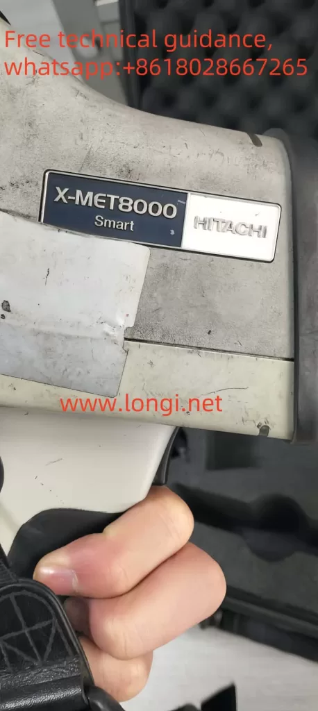
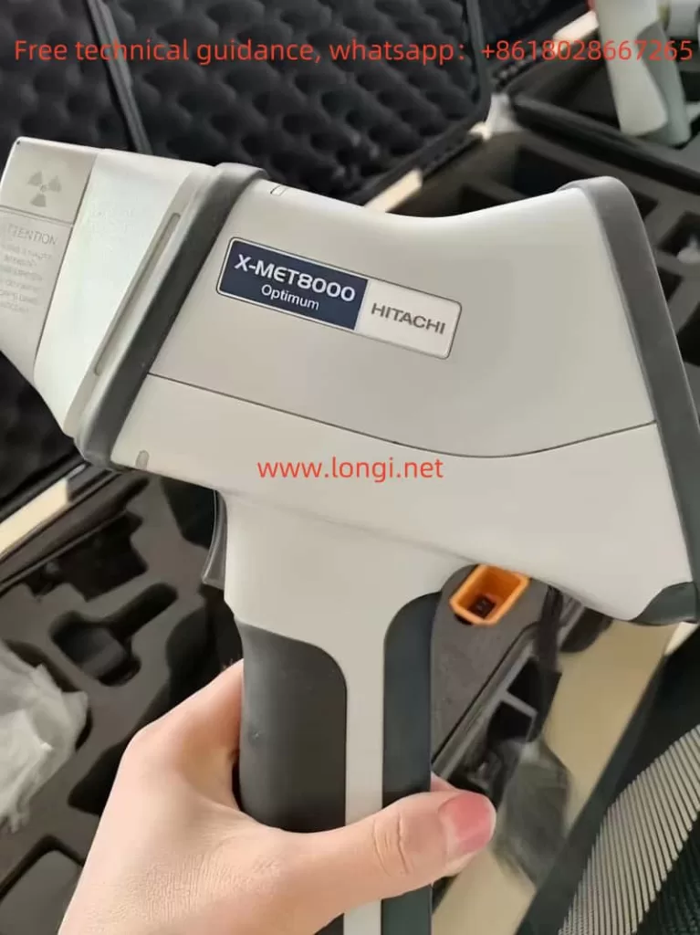
The Hitachi X-MET8000 spectrometer is an advanced, portable X-ray fluorescence (XRF) analyzer widely used for material testing and elemental analysis across various industries. This user guide covers the following aspects to help users maximize the device’s efficiency:
- Principles and Features of the X-MET8000 spectrometer.
- Usage Methods and Best Practices to ensure safe and effective operation.
- Error Codes: Common issues, their meanings, and troubleshooting steps.
By following this structured guide, users can maintain optimal device performance and prevent unnecessary downtime.
1. Principles and Features of the X-MET8000 Spectrometer
1.1 Working Principle
The X-MET8000 spectrometer operates based on X-ray fluorescence (XRF). When X-rays strike a material, they dislodge inner-shell electrons, creating vacancies. Electrons from higher energy levels fill these vacancies, releasing energy in the form of characteristic X-rays. By detecting and analyzing these emitted X-rays, the device can determine the elemental composition of the material.
1.2 Key Features
- Wide Element Range: Analyzes elements from magnesium (Mg) to uranium (U).
- Portability: Lightweight and rugged design for on-site measurements.
- High Accuracy: Equipped with advanced calibration options, including empirical and fundamental parameter (FP) calibrations.
- Touchscreen Interface: Intuitive controls and customizable menus.
- Battery Powered: Operates with a rechargeable battery for field use.
- Safety Features:
- Proximity Sensor: Prevents accidental X-ray exposure.
- X-Ray Shutter: Indicates when the X-ray source is active.
2. Usage Methods and Best Practices
2.1 Startup Procedure
- Switching On:
- Hold the power button for five seconds until the device powers on.
- Login:
- Use the default passwords: Operator (1111) or Supervisor (0000). Change passwords for security.
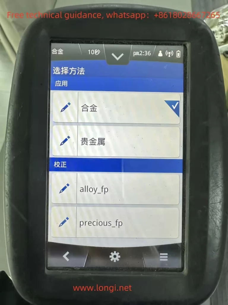
- Calibration:
- Use the factory calibration or perform a custom calibration depending on the sample type.
2.2 Measurement Procedure
- Prepare the Sample:
- Ensure the sample surface is clean and smooth to avoid measurement errors.
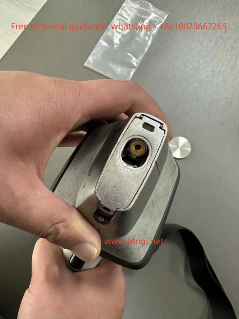
- Position the Device:
- Place the measurement window firmly against the sample. Ensure full coverage of the proximity sensor.
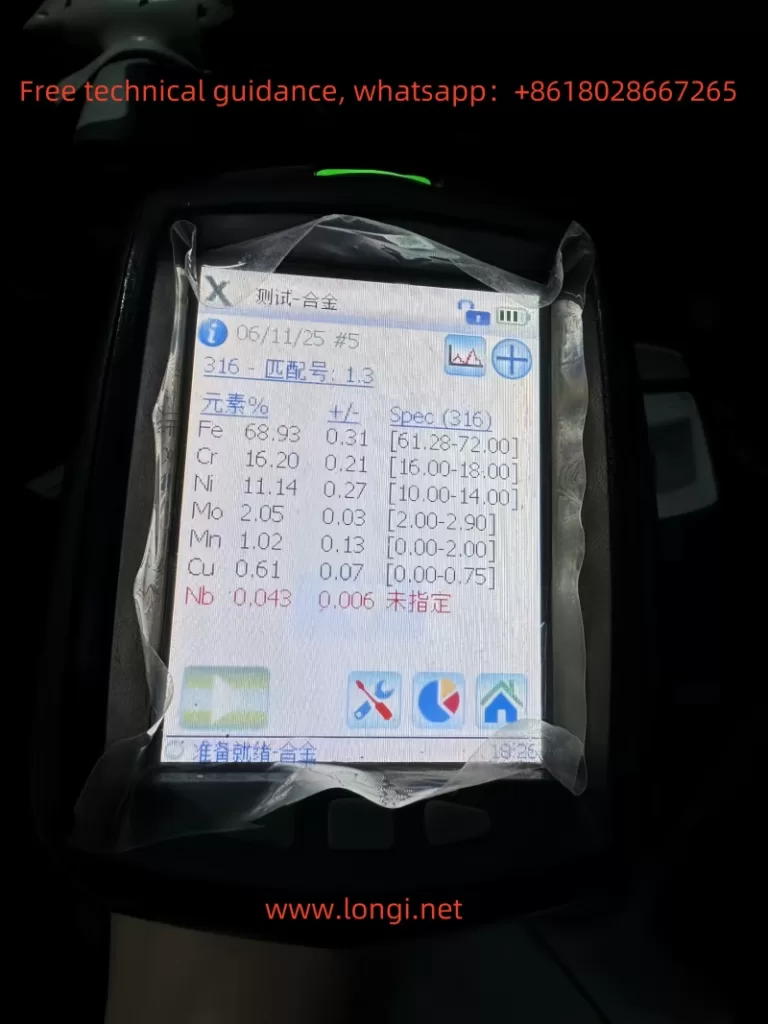
- Take Measurements:
- Pull and hold the trigger to activate the X-ray source. The results screen refreshes every two seconds.
- Release the trigger once the measurement is complete.
2.3 Data Management
- Batch Mode: Average measurements from multiple samples for consistency.
- Report Generation:
- Export results via USB, network share, or directly to a printer.
2.4 Maintenance
- Daily Cleaning: Wipe the measurement window with isopropyl alcohol.
- Weekly Maintenance: Inspect connectors, batteries, and protective films for wear or damage.
- Battery Care: Avoid overcharging to prolong battery life.
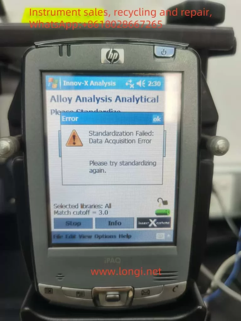
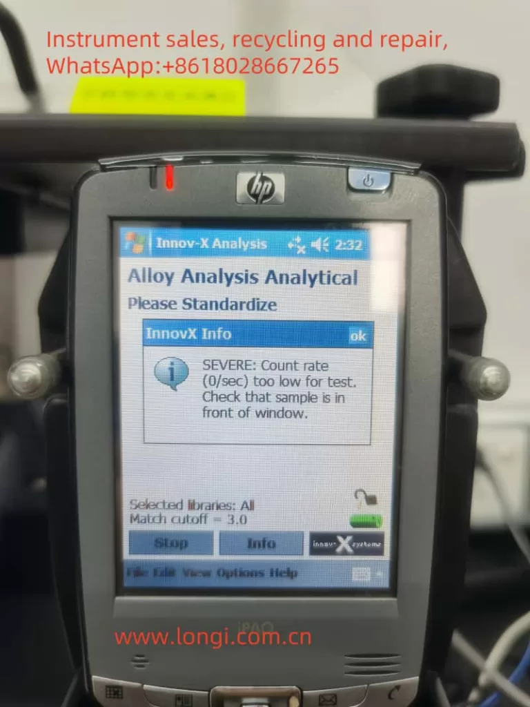
3. Troubleshooting and Error Codes
The X-MET8000 includes a robust diagnostic system to alert users to errors. Below are some common error codes, their meanings, and potential solutions.
3.1 Common Error Codes
| Error Code | Meaning | Possible Causes | Solutions |
|---|---|---|---|
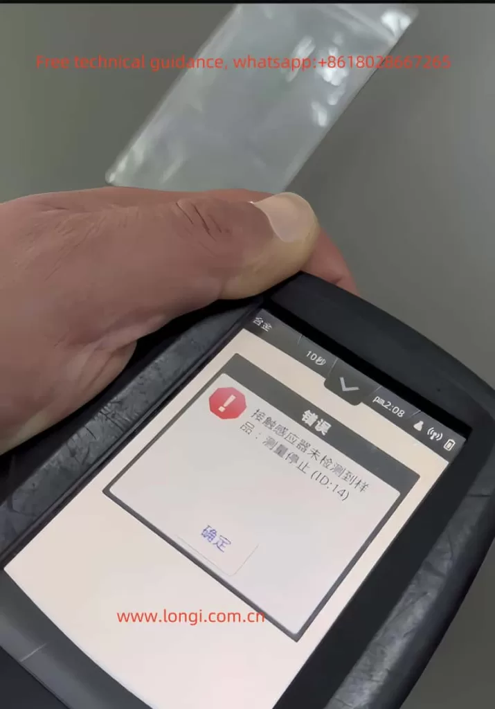
| ID-14 | Proximity sensor not detecting a sample | Sample not fully covering the window, sensor malfunction | Clean the sensor, ensure proper sample placement, or replace the sensor. |
| ID-07 | Low battery | Battery voltage too low | Recharge or replace the battery. |
| ID-21 | Calibration error | Incorrect calibration settings or sample mismatch | Recalibrate using the correct method or replace the reference sample. |
| ID-30 | Detector error | Issues with the X-ray detector, such as contamination or damage | Inspect and clean the detector; contact technical support if needed. |
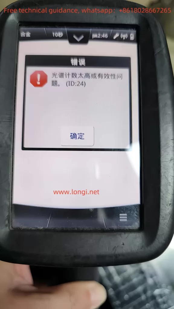
3.2 ID-14 Error: In-Depth Analysis
The ID-14 error occurs when the sample proximity sensor fails to detect the sample, causing the device to halt measurements. This can result from:
- Improper Sample Placement: The sample does not fully cover the sensor or has an irregular surface.
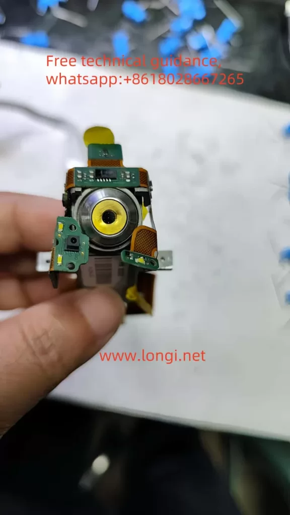
- Sensor Contamination: Dust, oil, or debris on the sensor blocks detection.
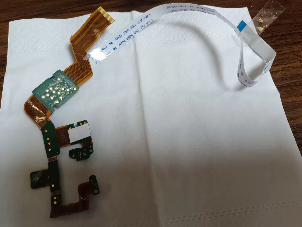
- Hardware Failure: Issues with the infrared emitter or receiver in the sensor.
Solution:
- Inspect the sample for proper placement and cleanliness.
- Clean the proximity sensor with a lint-free cloth and isopropyl alcohol.
- Test the sensor using a multimeter or infrared camera. Replace if necessary.
4. Safety and Operational Tips
- Safety First:
- Ensure the device is not pointed at people or animals during operation.
- Use only in accordance with local X-ray safety regulations.
- Avoid Misuse:
- Do not operate the spectrometer with a damaged proximity sensor or X-ray shutter.
- Store Properly:
- Keep the device in a dry, dust-free environment when not in use.
- Use Genuine Accessories:
- Only use approved batteries, chargers, and protective films to avoid device damage.
5. Conclusion
The Hitachi X-MET8000 is a versatile and reliable spectrometer for material analysis. By understanding its principles, following proper usage methods, and addressing common errors like ID-14 effectively, users can maximize its potential. Regular maintenance and adherence to safety practices will further enhance device longevity and performance. For unresolved issues, it is recommended to contact Hitachi’s technical support for professional assistance.