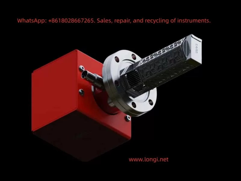
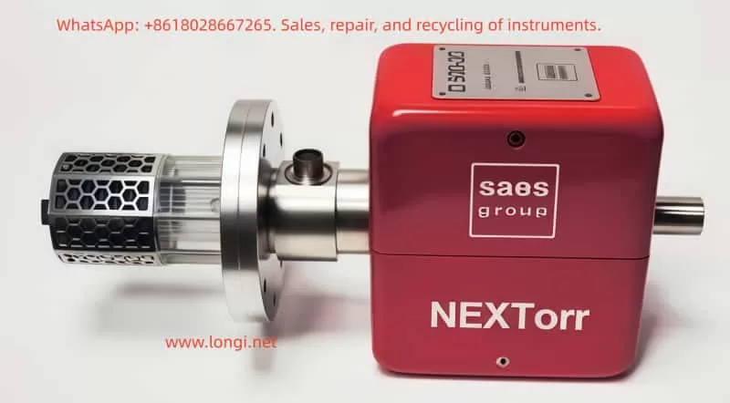
Posted on

Maintenance Analysis Report on YT‑3300 Smart Positioner Showing “TEST / FULL OUT 7535” Status

I. Overview and Equipment Background

This report addresses the status display of the Rotork YTC YT-3300 RDn 5201S smart valve positioner. The front panel shows the following:

TEST  
FULL OUT  
7535

The YT-3300 series smart positioner is produced by YTC (Young Tech Co., Ltd.), often labeled under the Rotork brand. It is designed for precise valve actuator control using a 4–20 mA input signal. The unit supports automatic calibration, self-diagnostics, manual testing, and performance optimization.


TEST FULL OUT

II. Interpretation of Display Information

1. TEST Mode

The “TEST” message indicates the unit is currently in self-test or calibration mode. This occurs typically during initial power-up, after parameter reset, or when manually triggered.

2. FULL OUT

“FULL OUT” means the actuator has moved to the end of its travel range—either fully open or fully closed—depending on the configured logic.

3. 7535

The number “7535” is not an error code. It usually represents the raw feedback signal from the internal position sensor, such as a potentiometer or encoder, scaled between 0–9999. This value gives the current travel position.


III. Possible Root Causes

The following table summarizes possible causes for this status:

No.Possible CauseDescription
1Power-on self-testAfter powering up or parameter loss, the device automatically initiates self-calibration.
2Manual test triggeredThe test mode may have been manually entered via front-panel buttons.
3Feedback sensor issueA stuck or damaged position sensor can cause the value (7535) to freeze or become invalid.
4Air pressure problemInsufficient or unstable air pressure may prevent the actuator from completing movement.
5Mainboard faultMalfunction of internal controller or microprocessor may lock the unit in test mode.

YT-3300 RDn 5201S

IV. Recommended Inspection and Repair Steps

1. Safety and Initial Checks

  • Disconnect the actuator from live control and ensure safe access.
  • Ensure that air pressure is fully vented to prevent unintended valve motion.
  • Confirm the unit is grounded properly (ground resistance <100 ohms).

2. Check Air Supply

  • Verify pressure gauges show clean, dry air within 0.14–0.7 MPa (1.4–7 bar).
  • Check for blocked air tubing or clogged filters.

3. Exit TEST Mode

  • Press the ESC button repeatedly to try returning to the RUN display.
  • If that fails, power cycle the unit and enter Auto Calibration mode via the front panel.

4. Execute Auto Calibration

  • Set the A/M switch to AUTO.
  • Use the keypad to navigate to “AUTO CAL” or “AUTO2 CAL” and execute.
  • The actuator will automatically stroke to both ends and calibrate zero and full travel points.
  • After successful calibration, the display should return to RUN mode.

5. Verify Position Feedback

If the value “7535” remains static or fails to reflect position changes:

  • Open the lower cover and check wiring to the potentiometer (typically yellow, white, blue wires).
  • Measure the feedback voltage (should range from ~0.5 to 4.5V DC).
  • If no variation is detected with actuator movement, the potentiometer or sensor board may need replacement.

6. Diagnostics and Alarm Monitoring

  • Enter the DIAGNOSTIC menu to check for alarm codes or travel deviation alerts.
  • If high or low limit alarms (e.g., HH ALRM or LL ALRM) are detected, reset as per standard procedures.

7. Functional Test and Tuning

  • After restoring to RUN mode, input varying mA signals and observe feedback value (PV) changes accordingly.
  • If actuator motion is slow or unstable, adjust Dead-Zone, Gain, or Filter settings to fine-tune performance.
  • Conduct partial stroke tests (PST) if available to verify control reliability.

TEST FULL OUT

V. Evaluation and Conclusion

Depending on the inspection and action taken, the following scenarios are possible:

  • If Auto Calibration completes successfully and feedback changes smoothly: No hardware failure is present. The unit was simply in test mode after reset.
  • If TEST mode persists and feedback value remains frozen: The position feedback sensor or its circuit is likely faulty and needs replacement.
  • If actuator fails to move despite calibration attempts: Check for blocked pneumatic valves, damaged tubing, or insufficient pressure.
  • If diagnostic menu shows active alarms: Follow alarm-specific reset instructions.

VI. Summary and Recommendations

  1. Preliminary Conclusion: The current “TEST / FULL OUT 7535” status likely indicates a post-reset auto-test, not a malfunction. However, persistent status or failed calibration points to feedback or hardware problems.
  2. Recommended Actions:
    • First attempt to complete auto calibration;
    • Check wiring, feedback sensor, and air supply;
    • Monitor diagnostic menu for error indicators;
    • Replace faulty components if auto-calibration cannot be completed.
  3. Follow-up Advice:
    • Acquire the official user manual for this specific model;
    • Record all air pressures, input/output values, alarms, and parameter settings during troubleshooting for future analysis;
    • If manual steps do not resolve the issue, contact the manufacturer or authorized support for further diagnostics or part replacement.

Posted on

KV-4C-24V-A-+A1 Weighing Display Controller

1. Product Overview

The KV-4C-24V-A-+A1 weighing display controller, developed by RAYTEI, is a high-precision signal display and control instrument designed for use with strain gauge load cells. It is ideal for monitoring and controlling forces such as tension, compression, weight, and pressure in industrial applications.

This controller features rich I/O capabilities, easy parameter configuration, dual-row LED real-time display, and analog/digital outputs. It integrates seamlessly into systems like packaging machines, injection molding, press machines, and testing equipment.


2. Features and Working Principle

2.1 Key Features

  • High Precision: Accuracy up to ±0.02% FS, suitable for demanding industrial measurements.
  • Dual Display Windows: Simultaneously shows current value and peak/valley/setting value.
  • Multiple Units Supported: Supports unit switching between kg, g, N, and t.
  • Multi-output: Includes 2 relay outputs (OUT1, OUT2), analog output (4–20mA, 0–10V, etc.).
  • RS-485 Communication: Supports Modbus protocol for PLC or HMI communication.
  • User-Friendly Panel: 5-key panel for quick access to settings, calibration, peak/valley, and zeroing.
  • Strong EMC Protection: Industrial-grade electromagnetic compatibility, suitable for harsh environments.

2.2 Working Principle

The controller reads analog microvolt signals from a load cell through a strain bridge input. It performs high-resolution A/D conversion and computes the corresponding force value. The system displays real-time values and outputs control signals (digital or analog) based on user-defined parameters like thresholds, peaks, valleys, or calibration settings.


3. Front Panel and Basic Operation

3.1 Indicator Overview

  • IN1: Input signal indicator (e.g., signal from load cell detected)
  • OUT1 / OUT2: Relay output indicators
  • Status LEDs:
    • Zero – Zeroing active
    • Mot – Motion state
    • Peak / Valley – Peak and valley tracking indicators

3.2 Key Functions

ButtonFunction Description
SWITCHSwitch between display modes or menu pages
ZEROTare (zero the current load)
OFTENCommon function key (save, view peaks, etc.)
SET/CALIEnter setup or calibration mode

4. Operating Instructions

4.1 Basic Startup Procedure

  1. Power On → Device performs self-check and version display.
  2. Connect Load Cell → Wire sensor input to IN1, VCC, and GND terminals.
  3. Tare the Scale → Ensure no load is applied, press and hold ZERO to reset to zero.
  4. Set Capacity → Enter SET/CALI to configure rated capacity and calibration points.
  5. Set Thresholds → Define upper/lower limits for OUT1/OUT2 triggers.
  6. Output Test → Apply force/load to verify relay activation or analog output change.
  7. Save Settings → Press and hold OFTEN to store changes.

5. Calibration Methods

5.1 Quick Calibration (CAL1)

Used for simple field calibration:

  1. Remove load → Display reads 0.
  2. Press SET/CALI to enter CAL1.
  3. Confirm zero load point.
  4. Apply full load → Enter expected value.
  5. Confirm and exit.

5.2 Multi-Point Calibration (CAL3)

For non-linear sensors or high-accuracy demand:

  • Supports up to 7 calibration points.
  • Sequentially apply known loads and enter each value.

5.3 Analog Output Calibration (CAL4)

To match analog signal range (4–20mA / 0–10V) with actual force range:

  • Requires digital multimeter to monitor output.
  • Use CAL4 to adjust span and offset precisely.

6. Parameter Settings Overview

Use SWITCH to navigate between function pages (F1 to F9). Below are key groups:

GroupDescription
F1Sampling, filter, unit selection
F2Peak/valley hold settings
F3Upper/lower limit for relay outputs
F4–F6Analog output scaling and mode
F7RS-485 communication settings
F9Password protection, parameter lock

Reminder: Always press OFTEN to save settings before exiting.


7. Maintenance Guidelines

7.1 Regular Calibration

  • Calibrate every 6–12 months for optimal accuracy.
  • Recalibrate if load cell or mounting configuration changes.
  • If analog output drifts, recalibrate using CAL4.

7.2 Cleaning and Handling

  • Clean panel surface with a dry soft cloth. Avoid solvents.
  • Prevent moisture from entering connector ports.
  • Periodically inspect terminal screws and wire condition.

7.3 Common Fault Diagnosis

Error CodeDescription
Err01Upper limit exceeded
Err02Lower limit exceeded
Err03No sensor signal
Err06RS-485 communication failed
Err09Power supply fault

In case of errors, verify power, sensor wiring, configuration, and hardware status.


8. Technical Specifications

SpecificationValue
Power Supply24VDC
Power Consumption≤3W
Accuracy±0.02%FS
Input TypeStrain gauge (±20mV)
OutputRelay × 2, Analog, RS-485
Panel Size107×44mm (cutout 92×44mm)
Mounting TypePanel embedded
Operating Temp-10℃ to +50℃

9. Summary

The KV-4C-24V-A-+A1 weighing controller is a robust, compact, and user-friendly industrial force display solution, featuring excellent accuracy and diverse I/O functionality. It is an ideal choice for automated production lines, force testing systems, press-fit machines, and similar applications.

For detailed Modbus register maps, calibration flowcharts, and electrical schematics, please refer to the official product manual provided by RAYTEI Load Cell Co., Ltd or consult their technical support team.


Posted on

SEW MOVIMOT MM D Series “ERROR 07” Fault Analysis and Solution

1. Meaning of ERROR 07 Fault Code

When the SEW-EURODRIVE MOVIMOT MM D series servo drive displays “ERROR 07,” it indicates “DC link voltage too high.” This fault typically occurs when the DC link voltage exceeds its rated range. According to the manual, the appearance of ERROR 07 can be caused by several factors, including short ramp times, faulty connections between the braking resistor and brake coil, incorrect internal resistance of the brake coil or braking resistor, thermal overload of the braking resistor, and invalid input voltage.

ERROR 7

1.1 Ramp Time Too Short

If the ramp time is set too short, the voltage in the DC link can rise too quickly, triggering the ERROR 07 fault. The ramp time controls the speed at which the drive accelerates. If the ramp time is too short, it can cause excessive current and voltage variations, leading to this fault.

1.2 Faulty Connection Between Brake Coil and Braking Resistor

The braking resistor and brake coil are crucial for controlling the DC link voltage during braking. If there is a poor connection between the brake coil and braking resistor, energy from braking cannot be absorbed effectively, causing the DC link voltage to rise too high and triggering ERROR 07.

1.3 Incorrect Internal Resistance of Brake Coil/Braking Resistor

The internal resistance of the brake coil or braking resistor must be within specific limits to effectively control braking energy. If the resistance deviates from the required value, the braking system will not function properly, and the DC link voltage may increase, causing ERROR 07.

1.4 Thermal Overload of the Braking Resistor

If the braking resistor is undersized or overloaded, it can overheat, leading to excessive DC link voltage. In such cases, the braking resistor must be properly sized to withstand the required braking torque and power without overheating.

1.5 Invalid Voltage Range of Supply Input Voltage

The input voltage to the drive must remain within its specified range. If the input voltage exceeds this range, it can lead to an excessively high DC link voltage. It is essential to verify that the supply voltage is within the permissible range as specified by the drive.

2. Solutions

Depending on the root cause of the ERROR 07 fault, here are the detailed diagnostic steps and solutions:

2.1 Extend the Ramp Time

If the ramp time is too short, you can extend it to allow the voltage to rise more gradually. Increasing the ramp time helps prevent the voltage from increasing too quickly, which could trigger the fault.

Steps:

  • Enter the drive’s configuration menu.
  • Find the ramp time parameter (typically labeled as “Ramp Time”).
  • Increase the ramp time to a value that allows the voltage to rise at a safe rate.
  • Save the settings and restart the drive to check if the fault is resolved.

2.2 Check the Connection Between the Brake Coil and Braking Resistor

If the connection between the braking resistor and brake coil is faulty, check all connection points to ensure they are secure and not loose or disconnected. If there is a problem, repair or replace the connection.

Steps:

  • Turn off the drive and disconnect the power.
  • Inspect the connections between the brake coil and braking resistor for any loose or broken connections.
  • Reconnect any faulty connections to ensure they are secure.
  • Power on the drive and test if the fault is cleared.

2.3 Check and Adjust the Internal Resistance of the Brake Coil/Braking Resistor

The internal resistance of the brake coil and braking resistor should match the required specifications. Use a multimeter to measure the resistance and compare it with the specifications in the drive’s technical manual.

Steps:

  • Use a multimeter to measure the resistance of the brake coil or braking resistor.
  • Compare the measured resistance with the recommended value in the technical data section of the manual.
  • If the resistance is incorrect, replace the brake coil or braking resistor with a new one that meets the specifications.

2.4 Properly Size the Braking Resistor

If the braking resistor is overloaded or improperly sized, it can cause thermal overload and lead to ERROR 07. The braking resistor should be able to absorb the energy produced during braking without overheating. Replace the braking resistor with one of the correct size.

Steps:

  • Calculate the required power and torque for the braking resistor based on the drive’s load.
  • Choose a braking resistor with sufficient power rating to handle the braking energy without overheating.
  • Install the appropriately sized braking resistor and test the drive to confirm the fault is resolved.

2.5 Check the Input Voltage

If the input voltage exceeds the rated range of the drive, it may cause an excessive DC link voltage. Use a multimeter to check that the supply voltage is within the allowable range. If the voltage is too high, consider adjusting the power supply or replacing it with one that provides the correct voltage.

Steps:

  • Use a multimeter to measure the input voltage to the drive.
  • Ensure the voltage is within the rated range specified for the drive (typically 380V to 500V AC).
  • If the input voltage is too high, check the power supply and adjust or replace it as necessary.

MM07D-503

3. Preventive Measures to Avoid ERROR 07

To prevent ERROR 07 from recurring, the following measures can be taken:

3.1 Regularly Check and Maintain the Braking System

Regularly inspect the braking resistor and brake coil for proper connections and resistance values. Ensure that they meet the required specifications to avoid issues with braking performance.

3.2 Optimize Cooling and Ventilation

Ensure the drive is installed in a well-ventilated area to prevent overheating. Regularly clean the drive’s cooling fins and ensure there are no obstructions blocking airflow. Keeping the drive cool will help avoid thermal overload issues.

3.3 Properly Size the Braking Resistor

Always select the correct size of braking resistor based on the load requirements. Ensure the braking resistor can handle the required braking torque and power without overheating.

3.4 Monitor Input Voltage Stability

Monitor the input voltage to ensure it remains within the permissible range. Using a stable power supply that provides consistent voltage within the rated range will help prevent issues with the DC link voltage.


4. Conclusion

The SEW MOVIMOT MM D series servo drive is an essential component in modern automation systems. The ERROR 07 fault, which occurs due to high DC link voltage, can be caused by several factors such as short ramp times, faulty braking system connections, incorrect internal resistance, thermal overload of the braking resistor, or invalid input voltage. By following the diagnostic steps and solutions outlined above, you can effectively address and resolve this issue. Regular maintenance, proper configuration, and careful monitoring of the drive’s operation will ensure long-term reliability and optimal performance.


Posted on

Working Principle and Application Guide of YT-3300 Smart Valve Positioner

The YT-3300 series from Rotork YTC is a high-performance electro-pneumatic smart valve positioner widely applied in industries such as petrochemical, power, pharmaceuticals, and process automation. It receives a 4-20 mA analog current signal from PLC or DCS, processes it through a built-in PID controller, and converts it into a pneumatic signal to precisely drive valve actuators. The unit also supports HART communication and optional feedback output (4-20 mA or digital) for closed-loop control.

This article explains its operating principle, core functions, product features, selection criteria, and usage guidelines in detail.

YT-3300

1. Working Principle

The YT-3300 receives a 4-20 mA signal (HART optional) representing the desired valve position. An internal 12-bit ADC samples the current and compares it to the actual valve position measured by an integrated travel sensor (either a magnetic resistance sensor or potentiometer). The PID controller calculates the necessary correction.

The output is then handled by an internal I/P (current-to-pressure) converter using a nozzle-flapper mechanism and miniature solenoid valves. The result is two precisely controlled pneumatic outputs (OUT1 / OUT2), used to actuate single- or double-acting pneumatic actuators.

The travel sensor’s reading can also be converted to a 4-20 mA signal or a digital communication protocol (e.g., HART, FF, PA) for remote monitoring.


2. Block Diagram (Closed-loop control)

      4-20 mA Input ─┐
                     ▼
  +------------------------------+
  | PID Controller + PWM Driver |
  +------------------------------+
           │            ▲
           ▼            │
  Miniature I/P Valve   │ Travel Sensor
           │            │ (NCS / Potentiometer)
           ▼            │
     OUT1 / OUT2 Pneumatic Output
           │
           ▼
  Pneumatic Actuator (Single/Double)

3. Key Functions

  • Digital PID Control: High-precision positioning within ±0.5% F.S.
  • Auto Calibration: AUTO1 / AUTO2 scan modes for fast commissioning.
  • Split Range Support: 4–12 mA / 12–20 mA assignment.
  • Feedback Options: 4-20 mA feedback (PTM module), mechanical limit switch (LSi), HART/FF/PA digital output.
  • Self-Diagnosis: Error codes such as OVER CUR, RNG ERR, or C ERR displayed on LCD screen.
  • Manual/Auto Switch: Supports bypass operations during maintenance.

4. Product Features

  • Integrated PID + I/P + feedback + diagnostics in one unit.
  • Compatible with both linear and rotary actuators.
  • IP66/NEMA 4X enclosure with explosion-proof or intrinsically safe options.
  • Supports SIL2/3 safety systems.
  • Maintenance-free NCS sensor and remote sensor options for high-temp or vibration zones.

5. Model Selection Guide

Code PositionOptionDescription
1L / RLinear or Rotary Actuator
2S / DSingle or Double Acting
3N / i / A / ENo Explosion / Intrinsically Safe
40 / 2 / F / PNone / HART / FF / PA Communication
51 / 2 / …PTM (Feedback) / LSi (Limit Switch)

Examples:

  • YT-3300RDN1101S: Rotary, double acting, no feedback, no HART.
  • YT-3300LSi-1201S: Linear, single acting, with 4-20 mA feedback + limit switch.

YT-3300 Wiring Block Diagram

6. Installation & Usage

Mechanical:

  • Ensure linkage lever aligns perpendicular at 50% stroke.
  • Use Namur bracket for rotary actuator mounting.

Pneumatics:

  • Use clean, dry air (0.14–0.7 MPa); OUT1 for single-acting, both OUT1/OUT2 for double-acting.

Electrical:

  • IN+ to signal source; IN– to common.
  • PTM feedback must use a separate loop.

Calibration:

  • Hold [MODE] to enter AUTO1.
  • Recalibrate using AUTO2 if positioning errors > 5%.
  • Adjust PID or Deadzone if valve hunts or is sluggish.

7. Common Faults

CodeDescriptionFix
OVER CURInput > 24 mACheck wiring, short circuit
RNG ERRStroke out of rangeRecalibrate or adjust lever
C ERRControl deviation too bigCheck air supply, valve jam

8. Application Scenarios

  • Control valves in chemical reactors
  • LNG valve control under sub-zero conditions
  • SIL-rated ESD valve systems
  • Remote installations requiring non-contact sensors

9. Conclusion

The YT-3300 series combines intelligent PID control, precise I/P conversion, diagnostics, and multiple feedback options into one robust, compact unit. Its flexibility in communication (analog or digital), safety compliance, and rugged design make it a superior choice for modern valve automation.